manuals.online logo
Brands
  1. Home
  2. •
  3. Brands
  4. •
  5. Cooper
  6. •
  7. Blower
  8. •
  9. Cooper Duroflow 4500 series User manual

Cooper Duroflow 4500 series User manual

This manual suits for next models

4

Popular Blower manuals by other brands

Lithium Earthwise LB20024 Operator's manual

Lithium Earthwise

Lithium Earthwise LB20024 Operator's manual

EINHELL GE-CL 36 Li E Original operating instructions

EINHELL

EINHELL GE-CL 36 Li E Original operating instructions

EINHELL VENTURRO 18/210 operating instructions

EINHELL

EINHELL VENTURRO 18/210 operating instructions

Troy-Bilt 657 Operator's manual

Troy-Bilt

Troy-Bilt 657 Operator's manual

Weed Eater VS2000BV instruction manual

Weed Eater

Weed Eater VS2000BV instruction manual

KRAUSMANN U37020-00 Operation manual

KRAUSMANN

KRAUSMANN U37020-00 Operation manual

GreenWorks Pro BLB482 Operator's manual

GreenWorks Pro

GreenWorks Pro BLB482 Operator's manual

ARIETE 2768 manual

ARIETE

ARIETE 2768 manual

NuTone 331H user guide

NuTone

NuTone 331H user guide

GÜDE GLB 200 18 Li-Ion Translation of the original instructions

GÜDE

GÜDE GLB 200 18 Li-Ion Translation of the original instructions

I.VA.CO. SC Series Operating and maintenance manual

I.VA.CO.

I.VA.CO. SC Series Operating and maintenance manual

DeWalt DCE100 instruction manual

DeWalt

DeWalt DCE100 instruction manual

Ryobi RY40404VN Operator's manual

Ryobi

Ryobi RY40404VN Operator's manual

Becker SV 7.330 operating instructions

Becker

Becker SV 7.330 operating instructions

Metabo AG 18 Pro instructions

Metabo

Metabo AG 18 Pro instructions

Desa GA3650TB installation instructions

Desa

Desa GA3650TB installation instructions

Hanseatic BVN 2500 operating instructions

Hanseatic

Hanseatic BVN 2500 operating instructions

Echo Power Blower PB-230LN Operator's manual

Echo

Echo Power Blower PB-230LN Operator's manual

manuals.online logo
manuals.online logoBrands
  • About & Mission
  • Contact us
  • Privacy Policy
  • Terms and Conditions

Copyright 2025 Manuals.Online. All Rights Reserved.

Price $5.00
DUROFLOW@ D-9-620
1st Edition
Supersedes BO11O
SERIES 4500
BLOWERS
SERVICE MANUAL
#
COOPER
Gardner-Denver
Industrial Machine~
Section One:
Section Two:
Section Three:
Section Four:
Section Five:
Section Six:
Section Seven:
Section Eight:
Section Nine:
Section Ten:
Section Eleven:
Section Twelve:
Section Thirteen:
DUROFLOW.
45 Series Blowers
Table of Contents
Introduction .......................................................2
Suggested Equipment and Supplies for aMajor Overhaul .................3
Teardown Procedure ................................................5
Policy Replacement Items ...........................................9
Major Parts Cleanup Procedures.. ....................................9
Major Parts Inspection Procedures ...................................10
Assembly Procedure ...............................................11
SpurGear Blowers .................................................18
Operating Limitations ..............................................19
Lubrication Recommendations. .....................................20
Parts Lists, Sectional and Exploded Views .............................21
Troubleshooting ..................................................23
Warranty Information ..............................................25
SECTION ONE
Introduction
This manual was prepared as aguide for the person in-
volved in the maintenance or overhaul of DuroFlow@ 45
Series Blowers utilizing splined rotor shafts and timing
gears. There are two versions, one of which uses spur
gears and the other, helical gears.
The helical gear version is the latest in the evolution of
DuroFlow blower technology. It differs from its prede-
cessor, the spur gear version, only in the gear tooth
configuration and the addition of aBelleville spring
behind one timing gear. On the helical gear blower,
rotor timing is accomplished by varying the position of
alock nut moving one timing gear axially against the
pressure of the Belleville spring washer. This slight
longitudinal movement of the drive gear in relation to
the idler gear changes the angular relationship be-
tween the two rotors.
In the spur gear version, rotor timing is accomplished
by selective assembly. Aparticular set of gears is
matched to aparticular set of rotors in order to achieve
the proper angular relationship between the two
rotors.
This manual is concerned primarily with the helical
gear version, which is currently in production.
Section Eight covers the differences in teardown and
reassembly procedure for the spur gear version.
Each of the four sizes of 45 Series blowers has four
configurations designated by the position of the drive
shaft as viewed from the drive end. The most common
configuration, designated vertical-top (VT), has the
drive rotor above the idler rotor and the airbox inlet
and discharge ducts are at the sides. In the vertical-
bottom (VB) configuration, the drive rotor is mounted
below the idler rotor. In the horizontal-left (H L)config-
uration, the drive rotor is to the left of the idler rotor
and the airbox inlet and discharge ducts are at the top
and bottom of the unit. In the horizontal-right (HR)
configuration, the drive rotor is mounted to the right
of the idler rotor.
The VT and HL configurations are identical except for
the position of the oil breather and the oil filler plug
and a change in the mounting plate in the HL. Like-
wise, the VB and the HR configurations correspond to
each other with the same differences as the VTand HL.
The VT-HL differs from the VB-HR in having adif-
ferent oil flinger on the drive end which is mounted on
the drive shaft in the VB-HR version rather than on
the idler shaft as in the VT-HL. Both oil flingers are
identical in the VT-HL version, whereas the drive end
flinger is more deeply dished than thegear end fiinger
in the VB-HR versions.
Since the VT version is the most common of the
various configurations, the illustrations and the tear-
down and reassembly procedures in this manual refer
to the VT configuration. The person involved in
overhauling one of the other versions of the blower
should keep in mind the differences noted in the
preceding paragraphs.
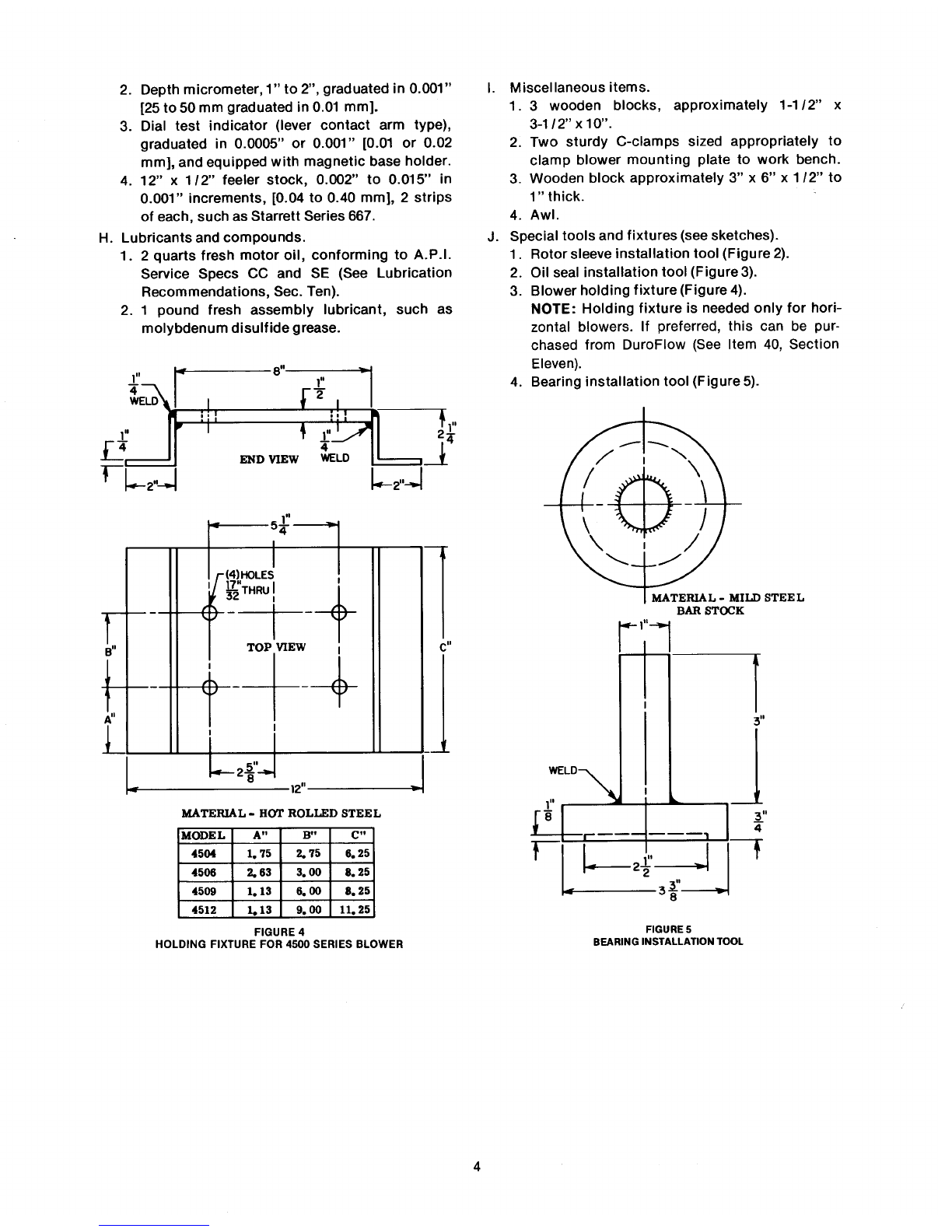
In addition, if overhauling either the HL or HR
versions, it is advisable to use aholding fixture to
secure the blower to the workbench. This can be
obtained from DuroFlow or it can be fabricated as in
Fig. 4.
It is suggested that the appropriate sections of this
manual be read and fully comprehended before any
specific service operation is attempted. Further, the
importance of aclean and adequately outfitted
workshop cannot be overemphasized. The success of
any major blower service effort depends upon
recognition of the fact that virtually every part
contained in the assembly is highly precise, and
hence, is vulnerable to the damaging effects of dirt,
moisture and rough handling.
IMPORTANT NOTICE
In mid-1981, modifications to the 45 Series end plates were made that are not shown in the text of this manual.
Blowers now require only one conventional breather cap. This difference will not affect service procedures.
When properly mounted, the air breather ports on modified blowers are always facing downward, and no
longer require breather caps. If these vent ports are threaded, abreather vent will be inserted. DO NOT PLUG
OR OBSTRUCT THESE AIR VENT PASSAGEWAYS!!
The oil sump breathing is now accomplished through the oil fill port. Ahexagonal bushing is inserted into the
oil fill hole, and the blowers’ only breather cap is placed in this bushing to vent the oil sump.
2
A.
B.
c.
SECTION TWO
Suggested Equipment and Supplies for aMajor Overhaul
Sturdy 3’ x6’ workbench, equipped with a5“ jaw
width, turret type machinist’s vise.
10 ton, 2-jaw, 5-1 /2” reach puller, such as Snap-
On CG-270.
Wrenches and PIiers.
1. 12“ adjustable (“Crescent” type).
2. 9/16“ six-or twelve-point box/open end com-
bination.
3. 3/8’ orl /2” square drive socket tools.
a. Ratchet handle.
b. 3“ to 6’ extension bar.
c. 9/16’ six-or twelve-point socket.
d. Torque wrench, 1ft-lb graduations to 50 ft-
Ib [7 mkg], such as Snap-On Nos. TE-50F or
TE-51 FTorqometers.
4. 3/4” square drive socket tools.
a. Ratchet or sliding tee handle.
b. 1-13/16’ six-or twelve-point socket.
c. Torque wrench, 5ft-lb graduations to 350
ft-lb [50 mkg], such as Snap-On No. TE-352
Torqometer.
Q
Iy ‘\
/:’ MATERIAL -COLD DRAWN
~SEAMLESS TUBING
2“ O. D, 0.180 WALL
I1/2” THICK MILD
~; r—2“-7sTEEL PLATE
IT3“
WELD
1
LJ
——. ———=
252,, J J
&2.82”&FIGURE 3
OIL SEAL INSTALLATION TOOL
5. Large internal snap ring pliers, such as Waldes
c! !IzWELD Tru-Arc No. S-6700.
~i’–
II
I‘~
I
I
I,1
II
I_
Ld
1.64” FIGURE 2
BEARING SLEEVE INSTALLATION TOOL
STEEL
D. Hammers.
1. 24 ounce ball or cross peen.
2. 3 pound plastic faced or rawhide mallet.
E. Chisels and punches.
1. 5/8” edge width flat chisel, blunted.
2. 5/16” shank diameter pin punch.
3. 118” point center punch.
F. Cleaning and deburring tools and supplies.
1.
2.
3.
4.
5.
6.
7.
Decreasing tank of chlorinated solvent, such as
perch lorethylene.
12 clean shop rags.
Stiff, natural bristle scrub brush.
Wire wheel or brush.
1-1 /2“ edge width gasket scraper.
8“ half round file, smooth or second cut.
Assorted silicone carbide or aluminum oxide
abrasive paper, in 240, 320 and 400 grits.
G. Measuring instruments.
1. Micrometer caliper, O“ to 1“, graduated in
0.001” [0 to 25 mm graduated in 0.01 mm].
2.
3.
4.
Depth micrometer, 1“ to 2“, graduated in 0.001”
[25 to 50 mm graduated in 0.01 mm].
Dial test indicator (lever contact arm type),
graduated in 0.0005” or 0.001” [0.01 or 0.02
mm], and equipped with magnetic base holder.
12“ x1/2” feeler stock, 0.002” to 0.015“ in
0.001” increments, [0.04 to 0.40 mm], 2strips
of each, such as Starrett Series 667.
H. Lubricants and compounds.
1. 2quarts fresh motor oil, conforming to A.P. I.
Service Specs CC and SE (See Lubrication
Recommendations, Sec. Ten).
2. 1 pound fresh assembly lubricant, such as
molybdenum disulfide grease.
MATERIAL -HOT ROLLED STEEL
MODE LIA“ IB“ Ic“
4504 I1.75 Z75 I6.25
1. Miscellaneous items.
1. 3wooden blocks, approximately 1-1 /2” x
3-1/2’’ xlo’.
2. Two sturdy C-clamps sized appropriately to
clamp blower mounting plate to work bench.
3. Wooden block approximately 3“ x6“ x1/2” to
1“ thick.
4. Awl.
J. Special tools and fixtures (see sketches).
1.
2.
3.
4.
Rotor sleeve installation tool (Figure’2).
Oil seal installation tool (Figure 3).
Blower holding fixture (Figure 4).
NOTE: Holding fixture is needed only for hori-
zontal blowers. If preferred, this can be pur-
chased from DuroFlow (See Item 40, Section
Eleven).
Bearing installation tool (Figure 5).
II73“
WELD
I
1,, .1 ,,
.——
E
1
‘2A<
FIGURE 4
HOLDING FIXTURE FOR 4500 SERIES BLOWER FIGURE 5
BEARING INSTALLATION TOOL
B.
SECTION THREE
Teardown Procedure
A. Preparation.
Before beginning the teardown sequence, the oil
should be drained from the unit. It is also sug-
gested that the usual accumulation of sludgy or
encrusted material be removed from the exterior.
This can best be accomplished by scouring with a
stiff bristle brush and soapy water, followed by a
pressure rinse with water. An acceptable alterna-
tive is steam cleaning, if the equipment is avail-
able. Because all salvable parts are made of cast
iron (or other ferrous alloy), virtually any heavy
duty, chemical cleaning agents—EXCEPT those
which are ACIDIC—are acceptable. It should be
noted, however, that when water (or steam) is used
in the cleaning process, the unit must be disas-
sembled immediately, and blown dry with com-
pressed air to prevent rusting of machined sur-
faces.
Teardown sequence.
NOTE: Numbers in parentheses ( ) refer to key
numbers in sectional and exploded assembly
drawings on pages 22 and 23.
1. Separation of the unit into basic subassem-
blies.
a. Securely fasten the unit to the workbench,
gear end facing out, using the mounting or
holding fixture and C-clamps (see Fig. 6).
FIGURE 6
BLOWER SECURED TO WORK STAND WITH “C” CLAMPS
b.
c.
d.
e.
FIGURE 7
REMOVING BREATHER CAPS FROM GEAR END PLATE
NOTE All screw threads on the blower are
standard right-hand threads.
Remove the 2breather caps from the gear
end plate (7) (see Fig. 7).
Remove eight pipe plugs.
Remove the 14 thru-bolts (4) and 2 cap
screws (5) from the gear end cover (l).
Remove the gear cover (1) from the gear end
plate (7).
NOTE: The gasket used to seal the cover/
end plate seam tends to bond tightly to
FIGURE 8
FOUR CAPSCREWS WITH SPACERS BEING TEMPORARILY REPLACED IN
GEAR END PLATE
5
f.
9.
both surfaces. After bolt and screw re-
moval, it. is usually necessary to drive off
the gear cover using the ball peen hammer
and blunted chisel.
Temporarily replace four of the cap screws
(4), two in each housing half, to retain the
gear end plate (7) during subsequent opera-
tions.
NOTE: Each cap screw must be bushed
with aspacer to prevent bottoming in the
absence of the gear cover (see Fig. 8).
If the timing gears appear to be undamaged,
it is advisable to check the gear backlash
before removing gears to determine whether
they can be reused (see Fig. 9).
(1)
(2)
(3)
(4)
(5)
(6)
Mount magnetic base dial indicator on
gear end plate with arm extending to-
ward drive gear.
Lock idler rotor stationary by wedging a
feeler gage between idler rotor and end
plate.
Place the tip of the indicator arm at ap-
proximately the center of the contact
surface on a tooth of the drive gear.
Rock the drive gear by hand and read the
total movement to the nearest .0005 in.
[.012 mm].
Rotate the idler rotor 90° and repeat
measurement three times.
Permissible gear backlash is .0025 to
.0055 in. [.064 to .141 mm].
NOTE: If backlash is outside specified
limits at this point, it does not neces-
sarily mean gears are unusable because
the excessive play could be caused by
worn bearings. However, if backlash is
within limits and there is no apparent
damage, the gears may definitely be
reused.
h. If the timing gears appear to be reusable, it
is advisable to make index marks on the
gears to facilitate rotor timing upon reas-
sembly. This can best be done by making
small punch marks on the ends of meshing
gear teeth with apin punch and hammer
(see Fig. 10).
FIGURE 10
INDEX MARKS ON ENDS OF GEAR TEETH
i. Place wood block between idler rotor lobe
and edge of inlet-discharge opening to pre-
vent rotor from turning. Loosen but do not
remove the flexlock nut from each rotor
shaft.
j. Move to drive end of blower. Locate the
tang of the spider washer (21) which was
bent into slot of lock nut (22). Bend the tang
out of the lock nut slot using pin punch and
hammer (see Fig. 11).
k. Chock drive rotor with wood block. Using
blunted flat chisel and hammer, loosen lock
FIGURE 9
CHECKING TIMING GEAR BACKLASH WITH DIAL INDICATOR
6
nut (see Fig. 12). Use caution not to dam-
age rotor shaft with chisel.
1. Remove lock nut and spider washer and
discard both as they will not be reused.
FIGURE 12
USING BLUNTED FLAT CHISEL AND BALL PEEN HAMMER TO LOOSEN
m
n.
o.
P.
q.
LOCK NUT
Remove the 14 cap screws (18), 14 lock
washers (6), and two cap screw and lock
washer assemblies (5) from the drive end
cover (30).
Remove the drive end cover. It may be
necessary to use blunted flat chisel and
hammer to loosen cover from end plate.
Remove bearing spacer (20) from drive shaft
(see Fig. 13).
Chock idler rotor with wood block. Remove
flexlock nut (27) from drive end of idler
shaft.
Remove oil flinger (29) and clamp washer
(28) from idler rotor shaft.
FIGURE 13
REMOVING BEARING SPACER FROM DRIVE SHAFT
r. Remove the drive end plate from the re-
mainder of the assembly using soft faced
mallet to loosen end plate from dowel pins
in housing halves (see Fig. 14).
CAUTION: The drive end plate weighs
about 40 pounds. Use care not to drop it.
FIGURE 14
USING SOFT FACED MALLET TO LOOSEN DRIVE END PLATE
s. Remove the flexlock nut (44) from the gear
end of the drive rotor shaft.
t. Remove the timing gear from the drive rotor
using the gear puller (see Fig. 15). Make
sure oil flinger (29) is turned so as not to
interfere with gear being removed from the
drive shaft.
u.
v.
w
FIGURE 15
USING PULLER TO REMOVE TIMING GEAR
Remove the Belleville spring (48) and dis-
card as it will not be reused.
Separate the drive rotor from the gear end
plate (see Fig. 16).
Remove the two cap screws and spacers
holding the upper housing half (12) to the
7
x.
y.
z.
aa.
bb.
cc.
dd .
ee.
gear end plate and remove the upper hous-
ing half.
Remove the flexlock nut (44) from the idler
rotor shaft.
Remove the oil flinger (29).
Use gear puller to remove the idler gear (42)
from the idler rotor (32).
Remove the idler rotor from the gear end
plate.
Remove the two cap screws and spacers
holding the gear end plate to the lower
housing half (39).
Remove the gear end plate from the lower
housing half.
CAUTION: The gear end plate weighs
about 35 pounds. Use care not to drop it.
Loosen the C-clamps and invert the lower
housing half on the workbench.
Remove the four cap screws (37) and lock
replaced as amatter of service policy.
(1)
(2)
(3)
(4)
(5)
Securely fasten the rotor in the vise,
using 2wood blocks to prevent marring
of the contoured surfaces.
Remove the seal ring (13) from the drive
end sleeve (14), using the awl to pry
apart the interlock, and then break the
ring from underneath.
Remove the seal ring (13) from the gear
end sleeve (11), as in Step 2.
Remove shims (15) from rotors.
Only as required in accordance with the
guidelines given under PREFACE, re-
move the sleeve(s) from the rotor shaft(s)
using the gear puller.
b. End plate subassembly.
PREFACE: Since all seals and bearings
should be replaced during overhaul as a
matter of service policy, both end plate
subassemblies must be completely disas-
sembled internally.
washers (38), and separate the mounting
plate (40) from the lower housing half.
(1)
(2)
(3)
(4)
(5)
(6)
Remove the 2retaining rings (26) from
their respective bearing sockets, using
the snap ring pliers.
Invert the end plate on the work bench,
and set on 2 oak blocks, so as to provide
3-1 /2” clearance between the plate and
bench, and to clear the edges of the
bearing sockets.
Remove the drive rotor bearing (9) or(l 7)
from its socket, using the ball peen
hammer and pin punch.
Remove the drive rotor oil seal (10) from
its socket, as in Step 3.
Remove the idler rotor bearing (9) or(17)
from its socket, as in Step 3.
Remove the idler rotor oil seal (10) from
FIGURE 16
REMOVING DRIVE ROTOR FROM GEAR END PLATE
2. Separation of the subassemblies into com-
ponent parts.
a. Rotor subassembly.
PREFACE: Except in unusual cases, the 4
end plugs in each rotor casting need not be
removed or replaced.
Rotor sleeves need only be removed from
their respective shafts for the purpose of
rotor or sleeve salvage.
The 2iron seal rings carried in the rotor
sleeves should always be removed and
c.
d.
its socket, as Step 3.
Housing half subassembly.
Except in unusual cases, the 4dowel pins
(34) and 2 ferrules (35) in each housing half
end surface need not be removed or re-
placed. However, the 2“O” rings (36) car-
ried on the ferrules of each housing half
shou Id always be replaced as amatter of
service policy.
Drive end cover.
(1)
(2)
Place cover on two wood blocks gasket
side up. With hammer and punch drive
out the seal (25). Discard seal as it will
be replaced.
Normally, there is no reason to remove
the two dowel pins (34) which are
pressed into the cover.
8
SECTION FOUR
Policy Replacement Items
It is suggested that the following parts be replaced savings when possible consequences are considered.
each time the 45 Series blower is disassembled re- It is not necessary to order these parts individually, as
gardless of apparent or measured condition. This DuroFlow offers afactory service parts kit for the 45
merely reflects sound service policy in that the reuse Series, splined shaft blower.
of these parts cannot be justified on the basis of cost
Item No. Description Qty. Per Unit Item No. Description Qty. Per Unit
9Roller Bearing 222 Lock Nut 1
10 Oil Seal 425 Oil Seal 1
13 Seal Ring 431 Gasket 2
15 Shim .002—.003— As 36 0Ring 4
.005—.007—.01 O” Required 46 Gasket 2
17 Ball Bearing 248 Belleville Spring 1
21 Lock Washer 1
SECTION FIVE
Major Parts Cleanup Procedures
A. Rotors.
1.
2.
3.
4.
5.
6.
Dip in decreasing tank agitating and brushing
to remove grease and oil.
Sandblast or wirebrush as necessary to remove
scale from rotor lobes. If sandblasting, mask
bearing sleeves, bearing spacers, and shafts
with rubber hose or tape to prevent erosion.
Lightly wet polish the bearing sleeves, bearing
spacers, and rotor shafts with crocus cloth.
Any burrs on rotor or shaft should be removed
with afile.
Dip again in decreasing tank and blow dry with
compressed air.
If rotor is not to be inspected and reused im-
mediately, dip in oil or rust preventative solu-
tion and seal in aclean plastic bag for storage.
B. End plates.
1.
2.
3.
4.
5.
6.
Dip in decreasing tank agitating and brushing
to remove grease and oil.
Sandblast or wirebrush as necessary to remove
scale. If sandblasting, place plugs in seal ring
bores to prevent erosion during blasting.
Lightly wet polish the seal ring bores with 400
grit abrasive paper.
Remove burrs with file.
Dip in decreasing tank and blow dry with com-
pressed air.
If end plate is not to be inspected and reused
immediately, dip in oil or rust preventative
solution and seal in clean plastic bag for stor-
age.
C. Housing halves.
1.
2.
3.
4.
5.
6.
Dip in decreasing tank agitating and brushing
to remove grease and oil.
Sandblast or wirebrush as necessary to remove
scale.
Wet polish the machined concave surface with
240 grit abrasive paper.
File burrs on machined surfaces.
Dip in decreasing tank and blow dry with com-
pressed air. Use particular care to insure that
all foreign matter is purged from oil passages.
If housing is not to be inspected and reused
immediately, dip in oil or rust preventative
solution and seal in clean plastic bag for
storage.
D. Timing gears.
1.
2.
3.
4.
5.
Dip in decreasing tank to remove grease and oil.
Wirebrush as necessary to remove scale.
Remove nicks and burrs with file.
Dip in decreasing tank and blow dry with com-
pressed air.
If gears are not to be inspected and reused im-
mediately, dip in oil or rust preventative solu-
tion and seal in clean plastic bag for storage.
E. Covers.
1. Dip in decreasing tank agitating and brushing
to remove grease and oil.