CopperOptics Pairain PG-Plus PCS-719 User manual

PG-PLUS
23-INCH CENTRAL OFFICE TERMINAL SHELF
PAIRGAIN TECHNOLOGIES, INC.
ENGINEERING SERVICES TECHNICAL PRACTICE
SECTION 950-719-100-03
Revision History of this practice.
Revision 03—September 2, 1997
A) Added Pin Assignment Table
B) Corrected Connection process
Model List Number Part Number CLEI Code
PCS-719 1 150-1619-01 S9MTAB0ARA

Revision 03 September 2, 1997 Section 950-719-100
Page ii PairGain Engineering - Plant Series PG-Plus PCS-719
©Copyright 1997 PairGain® Technologies, Inc.
PairGain is a registered trademark, and PG-Plus is a trademark of PairGain Technologies, Inc.
Other product names mentioned in this manual are used for identification purposes only and may be trademarks and/or registered
trademarks of their respective Information contained in this document is company private to PairGain Technologies, Inc. and shallnot
be modified, used, copied, reproduced or disclosed in whole or in part without the written consent of PairGain.

Section 950-719-100 September 2, 1997 Revision 03
PG-Plus PCS-719 PairGain Engineering - Plant Series Page iii
TABLE OF CONTENTS
Using This Technical Practice.................................................................................................................................... iv
Inspecting Your Shipment.......................................................................................................................................... iv
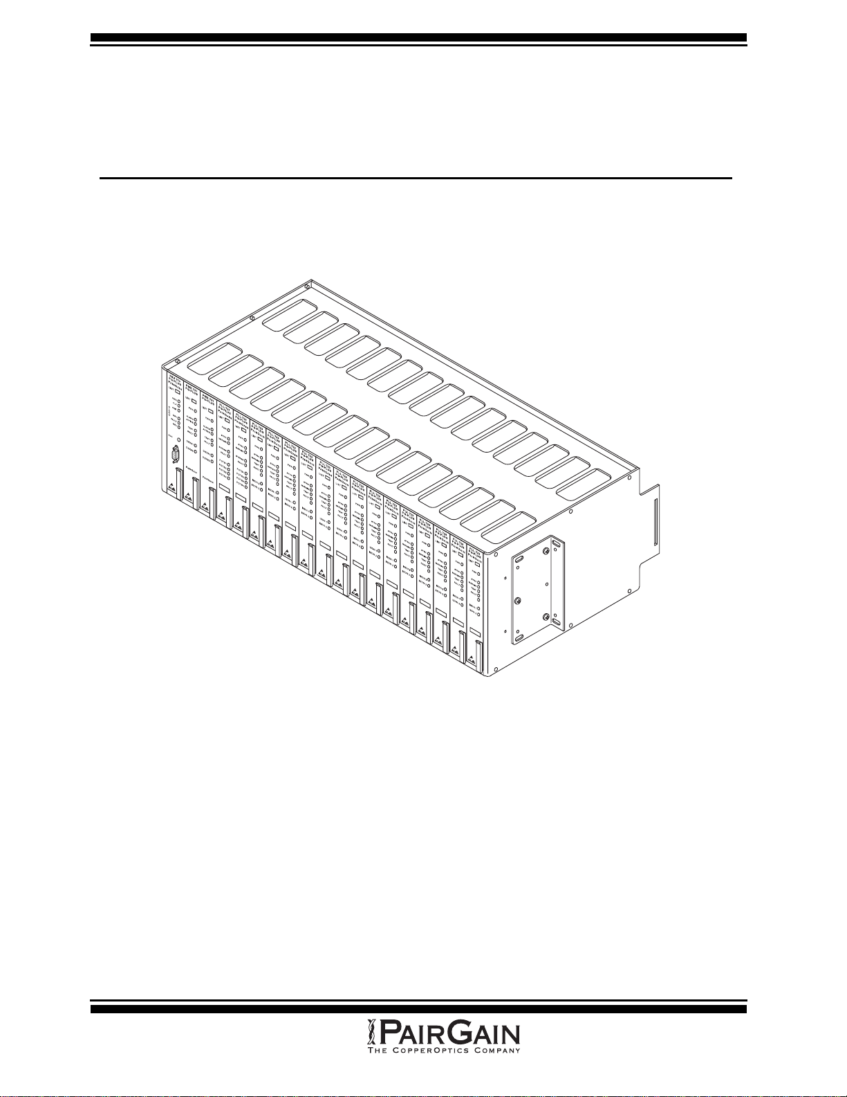
PCS-719 Overview ....................................................................................................................................................... 1
Description and Features ..........................................................................................................................................................1
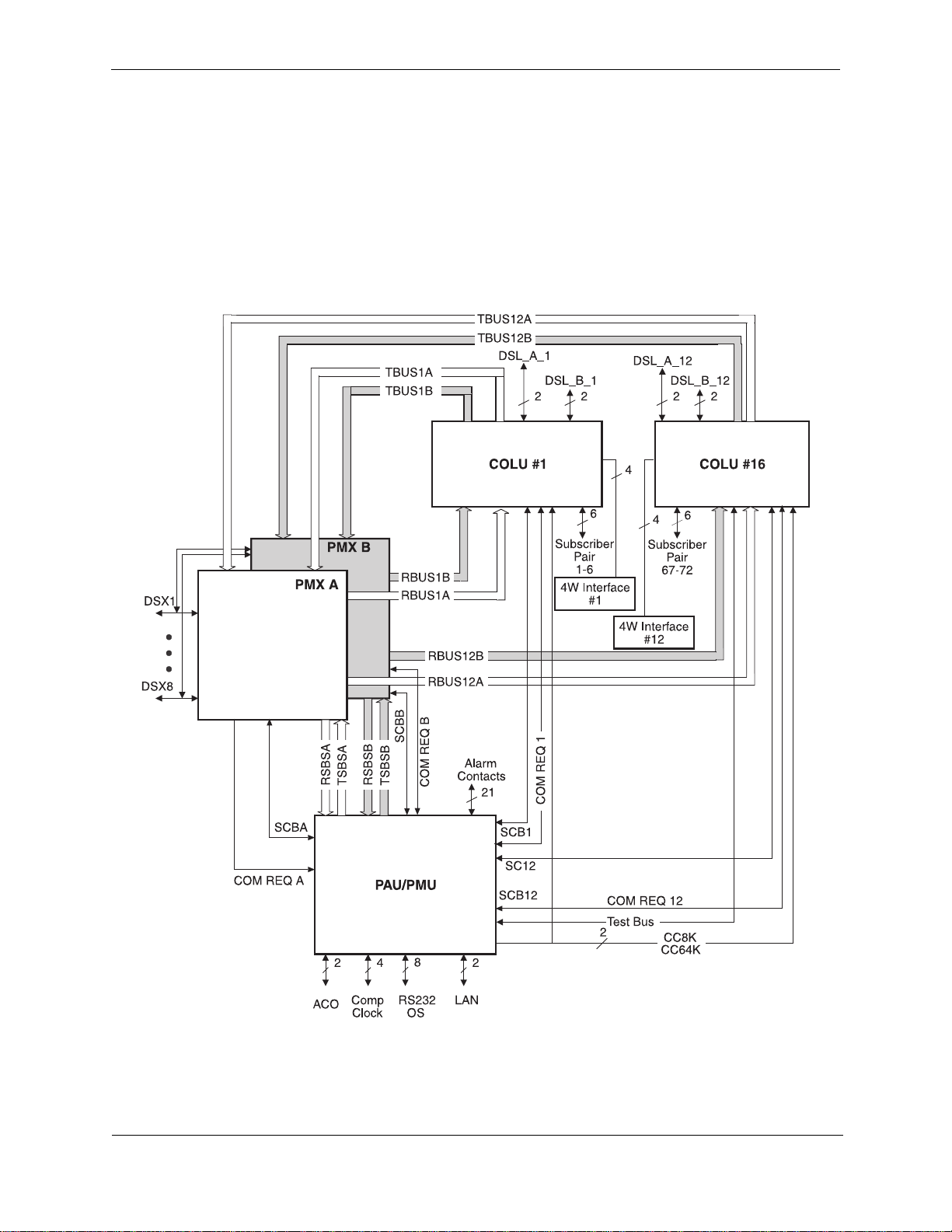
Theory of Operation ................................................................................................................................................................. 2
Data Channel Overview ....................................................................................................................................................2
Serial Communications Bus .............................................................................................................................................3
Composite Clock Signals ..................................................................................................................................................3
Test Bus ............................................................................................................................................................................3
Communication Requests .................................................................................................................................................3
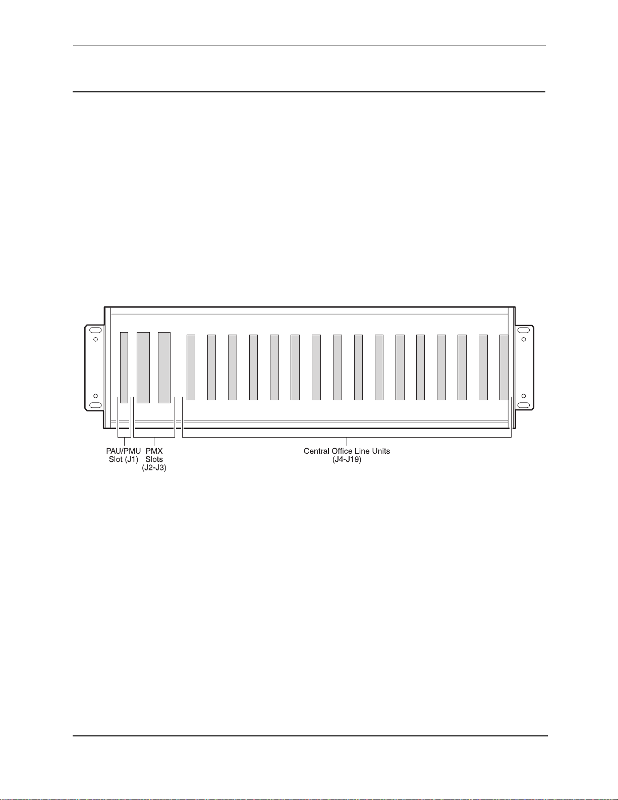
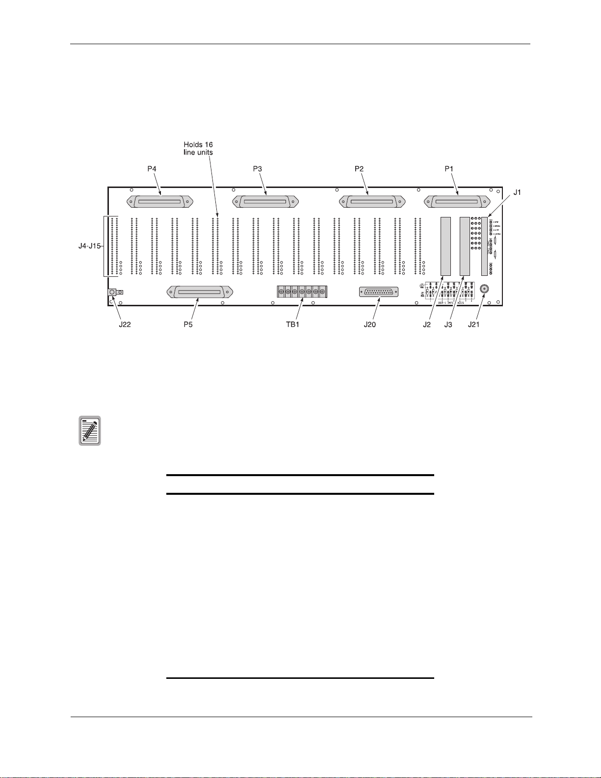
Backplane Connections ............................................................................................................................................................ 4
Power ................................................................................................................................................................................5
COLU HDSL ....................................................................................................................................................................5
Two-Wire Subscriber Pairs ..............................................................................................................................................5
Four-Wire Pairs ................................................................................................................................................................5
COLU Edge Card Connectors ..........................................................................................................................................6
Alarm Cutoff ..................................................................................................................................................................13
Alarm Contacts ...............................................................................................................................................................14
OS Interface ....................................................................................................................................................................14
LAN Interface .................................................................................................................................................................14
DSX1 Connections .........................................................................................................................................................15
PAU/PMU Connector .....................................................................................................................................................15
PMX Connector ..............................................................................................................................................................16
Specifications .........................................................................................................................................................................18
Installation and Test .................................................................................................................................................. 18
Required Tools and Test Equipment ......................................................................................................................................18
Power ......................................................................................................................................................................................18
Mounting ................................................................................................................................................................................18
Wiring Access ........................................................................................................................................................................19
Alarm Leads ...........................................................................................................................................................................19
HDSL Lines ............................................................................................................................................................................19
Subscriber Lines .....................................................................................................................................................................19
Connections ............................................................................................................................................................................19
Ground Connections .......................................................................................................................................................19
Power Connections .........................................................................................................................................................20
Redundant-Shelf Powering .............................................................................................................................21
Split-Shelf Powering .......................................................................................................................................22
Single-Source Powering .................................................................................................................................23
Audible and Visual Alarm Connections .........................................................................................................................24
Subscriber Connections From CO ..................................................................................................................................25
Composite Clock Connections .......................................................................................................................................32
HDSL Wiring .................................................................................................................................................................33
External ACO Connection ..............................................................................................................................................34
Turn-Up and Test ...................................................................................................................................................................34
Product Support .........................................................................................................................................................35
Technical Support ...................................................................................................................................................................35
Warranty .................................................................................................................................................................................35
FCC Compliance ....................................................................................................................................................................35
Modifications ..........................................................................................................................................................................36
Abbreviations ............................................................................................................................................................. 36

Revision 03 September 2, 1997 Section 950-719-100
Page iv PairGain Engineering - Plant Series PG-Plus PCS-719
USING THIS TECHNICAL PRACTICE
Three types of messages, identified by icons, appear in the text:
INSPECTING YOUR SHIPMENT
Upon receipt of the equipment:
• Unpack each container and visually inspect it for signs of damage. If the equipment has been damaged in
transit, immediately report the extent of damage to the transportation company and to PairGain. Order
replacement equipment, if necessary.
• Check the packing list to ensure complete and accurate shipment of each listed item. If the shipment is short
or irregular, contact PairGain as described in the Warranty. If you must store the equipment for a prolonged
period, store the equipment in its original container.
A note informs you of special circumstances.
A caution indicates the possibility of equipment damage.
A warning indicates the possibility of personal injury.

Section 950-719-100 August 22, 1997 Revision 03
PG-Plus PCS-719 PairGain Engineering - Plant Series Page 1
PCS-719 OVERVIEW
This practice describes the PairGain PG-Plus PCS-719 List 1B Central Office Terminal 23-inch shelf (COTS) which
supports up to sixteen PG-Plus subscriber carrier systems.
DESCRIPTION AND FEATURES
The PCS-719 provides convenient mounting of COTS Plus Alarm Unit (PAUs) and Central Office Line Units
(COLUs); and furnishes termination points for subscriber circuits, alarm, power, and metallic test access. All circuit
boards are installed from the front of the shelf. Interconnections for PG-Plus units are located on the backplane at the
rear of the shelf. The PCS-719 COTS accommodates the following PG-Plus units (see Figure 1):
•16COLUs
• Two Multiplexer Units (PMX)
• One PAU or one PG-Plus Management Unit (PMU) (interchangeable)
Figure 1
PCS-719 COTS
The COTS features:
• Wire-wrap connections for HDSL, alarm cutoff, and alarm relays
• Screw terminal connections for frame ground and Central Office (CO) battery
• DB-25 connector for network communications
• 64-pin Telco connector for four-wire service connections
• 50-pin Telco connector for CO lines

Revision 03 August 22, 1997 Section 950-719-100
Page 2 PairGain Engineering - Plant Series PG-Plus PCS-719
THEORY OF OPERATION
Data Channel Overview
The COTS backplane uses redundant Pulse Code Modulation (PCM) transmit and receive buses and Serial
Communications buses (SCB) for data transfer and intra-shelf communications. Individual clock, data, and
synchronization buses originate from the PMX cards and terminate at each COLU position. The COTS provides the
signal connectivity and -48 V dc power distribution in the COTS. Figure 2 shows the backplane signal
interconnection.
Figure 2
Backplane Signal Configuration

Section 950-719-100 August 22, 1997 Revision 03
PG-Plus PCS-719 PairGain Engineering - Plant Series Page 3
Serial Communications Bus
The Serial Communications Bus (SCB) provides the means for the PAU/PMU to communicate with all other boards
in the COTS to allow:
• Software downloads
• Coordination of PMX equipment protection
• Generation of status, alarm, and performance reports through the PG-Plus Console menus
• Provisioning of each unit installed in the shelf through the PG-Plus Console menus
The serial bus operates in a master/slave polled environment with the PAU/PMU functioning as theSCB master.Each
COLU position has its own SCB connection to avoid conflict. The SCB acts as the “card present” line to notify the
PAU/PMU board that a line unit is present in the shelf. Figure 3 shows the communication line between the
PAU/PMU and any COLU. If a COLU is not installed, the line is pulled high to notify the PAU/PMU that a line unit
is not present and data should not be sent. When installed, each card pulls its line low.
Figure 3
Communication Line Between PAU/PMU and COLU
Composite Clock Signals
Composite clock signals are a 64 kHz bipolar clock with 8 kHz bipolar violations. The 64 kHz clock and the 8 kHz
violations define the bit and byte boundaries of DDS data as it is transferred within a CO. In support of the DDS
interfaces, PG-Plus defines two composite clock interfaces at the PAU/PMU card slot. The PAU/PMU selects the
clock and translates it into bit and byte clocks, which it then distributes to the COLUs. Wire-wrap pins on the
backplane allow the composite clock source to be terminated or daisy-chained to another shelf.
Test Bus
The Test Bus provides a common Tip/Ring bus from the COLUs to the PAU/PMU. This bus allows the PAU/PMU
to provide a resistive signature to any of the tested subscriber circuits.
Communication Requests
The COTS provides communication requests from each of the cards to the PAU/PMU slot. These signals are used by
the COLU and PMX units to initiate communication with the PAU/PMU.

Revision 03 August 22, 1997 Section 950-719-100
Page 4 PairGain Engineering - Plant Series PG-Plus PCS-719
BACKPLANE CONNECTIONS
Each COTS supports the connection of up to sixteen COLUs, two PMX units and one PAU/PMU. The backplane of
the PCS-719 COTS contains the connectors shown in Figure 4 and Table 1. Wiring external to the COTS should
follow the provisions of the current edition of the National Electrical Code and applicable local codes.
Figure 4
PCS-719 Shelf Backplane
The following sections identify each connector by type and function.
Information in Tables 2 through 20 can be used for diagnostic and troubleshooting procedures
under the direction of an authorized PairGain technical support representative.
Table 1
Backplane Connectors
Connector Description
J1 PAU or PMU connector
J2 PMX 1 connector
J3 PMX 2 connector
J4 - J19 COLU HDSL connectors
J20 DB-25 (RS-232) connector
J21 LAN connector
J22 Frame Ground
P1 - P4 Telco connectors for 2-wire interfaces
P5 Telco connector for 4-wire interfaces
TB1 Seven-position power-terminal strip

Section 950-719-100 August 22, 1997 Revision 03
PG-Plus PCS-719 PairGain Engineering - Plant Series Page 5
Power
The COTS backplane has a seven-position power-terminal strip (TB1) that provides connections for dual -48 V dc,
common battery return, and frame ground to each of the card slots by way of screw terminals. The COTS can be wired
for redundant powering, split-powering, or single-source powering depending upon requirements.
COLU HDSL
There are sixteen sets of wire-wrap HDSL interfaces on the COTS backplane, one for each COLU slot (J4 - J15 where
J4 corresponds to slot LU1, and J19 corresponds to slot LU16). Each COLU slot is also equipped with a second pair
of HDSL wire-wrap pins for future XDSL configurations.
Two-Wire Subscriber Pairs
A total of 96 two-wire subscriber pairs terminate at the Telco connectors (P1, P2, P3, and P4) on the PG-Plus COTS
backplane. Six pairs route to each of the sixteen COLUs. See Tables 26 through 30 for P1, P2, P3, and P4 connector
pinouts.
Four-Wire Pairs
The COTS provides a total of sixteen four-wire data interfaces for services such as DDS or Ethernet. They are
segregated from the two-wire pairs on a separate Telco connector (P5, see Table 30). One four-wire connection is
provided for each COLU slot.

Revision 03 August 22, 1997 Section 950-719-100
Page 6 PairGain Engineering - Plant Series PG-Plus PCS-719
COLU Edge Card Connectors
Tables 2 through 17 show the backplane connector pinouts for each COLU slot.
Table 2
COLU #1 (J4) Connector Pinouts
Pin # Assignment Assignment Pin #
49 TIP1 RING1 50
47 TIP2 RING2 48
45 TIP3 RING3 46
43 TIP4 RING4 44
41 TIP5 RING5 42
39 TIP6 RING6 40
37 <BURN IN> – 38
35 CC8KA CC64KA 36
33 INTRPT1- SCB1 34
31 RDATA1 RDATB1 32
29 CLKA1 CLKB1 30
27 RSIGA1 RSIGB1 28
25 FSYNCA1 FSYNCB1 26
23 TDATA1 TDATB1 24
21 TSIGA1 TSIGB1 22
19 TSTTIP TSTRING 20
17 GND GND 18
15 BATA_L BATA_L 16
13 BATB_L BATB_L 14
11 –– 12
9HTIPA1 HTIPB1 10
7HRINGA1 HRINGB1 8
5FGND FGND 6
34WRXT1 4WRXR1 4
14WTXT1 4WTXR1 2
Table 3
COLU #2 (J5) Connector Pinouts
Pin # Assignment Assignment Pin #
49 TIP7 RING7 50
47 TIP8 RING8 48
45 TIP9 RING9 46
43 TIP10 RING10 44
41 TIP11 RING11 42
39 TIP12 RING12 40
37 <BURN IN> – 38
35 CC8KA CC64KA 36
33 INTRPT2- SCB2 34
31 RDATA2 RDATB2 32
29 CLKA2 CLKB2 30
27 RSIGA2 RSIGB2 28
25 FSYNCA2 FSYNCB2 26
23 TDATA2 TDATB2 24
21 TSIGA2 TSIGB2 22
19 TSTTIP TSTRING 20
17 GND GND 18
15 BATA_L BATA_L 16
13 BATB_L BATB_L 14
11 ––12
9
HTIPA2 HTIPB2 10
7HRINGA2 HRINGB2 8
5FGND FGND 6
34WRXT2 4WRXR2 4
14WTXT2 4WTXR2 2

Section 950-719-100 August 22, 1997 Revision 03
PG-Plus PCS-719 PairGain Engineering - Plant Series Page 7
Table 4
COLU #3 (J6) Connector Pinouts
Pin # Assignment Assignment Pin #
49 TIP13 RING13 50
47 TIP14 RING14 48
45 TIP15 RING15 46
43 TIP16 RING16 44
41 TIP17 RING17 42
39 TIP18 RING18 40
37 <BURN IN> – 38
35 CC8KA CC64KA 36
33 INTRPT3- SCB3 34
31 RDATA3 RDATB3 32
29 CLKA3 CLKB3 30
27 RSIGA3 RSIGB3 28
25 FSYNCA3 FSYNCB3 26
23 TDATA3 TDATB3 24
21 TSIGA3 TSIGB3 22
19 TSTTIP TSTRING 20
17 GND GND 18
15 BATA_L BATA_L 16
13 BATB_L BATB_L 14
11 –– 12
9HTIPA3 HTIPB3 10
7HRINGA3 HRINGB3 8
5FGND FGND 6
34WRXT3 4WRXR3 4
14WTXT3 4WTXR3 2
Table 5
COLU #4 (J7) Connector Pinouts
Pin # Assignment Assignment Pin #
49 TIP19 RING19 50
47 TIP20 RING20 48
45 TIP21 RING21 46
43 TIP22 RING22 44
41 TIP23 RING23 42
39 TIP24 RING24 40
37 <BURN IN> – 38
35 CC8KA CC64KA 36
33 INTRPT4- SCB4 34
31 RDATA4 RDATB4 32
29 CLKA4 CLKB4 30
27 RSIGA4 RSIGB4 28
25 FSYNCA4 FSYNCB4 26
23 TDATA4 TDATB4 24
21 TSIGA4 TSIGB4 22
19 TSTTIP TSTRING 20
17 GND GND 18
15 BATA_L BATA_L 16
13 BATB_L BATB_L 14
11 –– 12
9HTIPA4 HTIPB4 10
7HRINGA4 HRINGB4 8
5FGND FGND 6
34WRXT4 4WRXR4 4
14WTXT4 4WTXR4 2

Revision 03 August 22, 1997 Section 950-719-100
Page 8 PairGain Engineering - Plant Series PG-Plus PCS-719
Table 6
COLU #5 (J8) Connector Pinouts
Pin # Assignment Assignment Pin #
49 TIP25 RING25 50
47 TIP26 RING26 48
45 TIP27 RING27 46
43 TIP28 RING28 44
41 TIP29 RING29 42
39 TIP30 RING30 40
37 <BURN IN> – 38
35 CC8KA CC64KA 36
33 INTRPT5- SCB5 34
31 RDATA5 RDATB5 32
29 CLKA5 CLKB5 30
27 RSIGA5 RSIGB5 28
25 FSYNCA5 FSYNCB5 26
23 TDATA5 TDATB5 24
21 TSIGA5 TSIGB5 22
19 TSTTIP TSTRING 20
17 GND GND 18
15 BATA_L BATA_L 16
13 BATB_L BATB_L 14
11––12
9 HTIPA5 HTIPB5 10
7 HRINGA5 HRINGB5 8
5FGNDFGND6
3 4WRXT5 4WRXR5 4
1 4WTXT5 4WTXR5 2
Table 7
COLU #6 (J9) Connector Pinouts
Pin # Assignment Assignment Pin #
49 TIP31 RING31 50
47 TIP32 RING32 48
45 TIP33 RING33 46
43 TIP34 RING34 44
41 TIP35 RING35 42
39 TIP36 RING36 40
37 <BURN IN> – 38
35 CC8KA CC64KA 36
33 INTRPT6- SCB6 34
31 RDATA6 RDATB6 32
29 CLKA6 CLKB6 30
27 RSIGA6 RSIGB6 28
25 FSYNCA6 FSYNCB6 26
23 TDATA6 TDATB6 24
21 TSIGA6 TSIGB6 22
19 TSTTIP TSTRING 20
17 GND GND 18
15 BATA_L BATA_L 16
13 BATB_L BATB_L 14
11––12
9 HTIPA6 HTIPB6 10
7 HRINGA6 HRINGB6 8
5 FGND FGND 6
3 4WRXT6 4WRXR6 4
1 4WTXT6 4WTXR6 2

Section 950-719-100 August 22, 1997 Revision 03
PG-Plus PCS-719 PairGain Engineering - Plant Series Page 9
Table 8
COLU #7 (J10) Connector Pinouts
Pin # Assignment Assignment Pin #
49 TIP37 RING37 50
47 TIP38 RING38 48
45 TIP39 RING39 46
43 TIP40 RING40 44
41 TIP41 RING41 42
39 TIP42 RING42 40
37 <BURN IN> – 38
35 CC8KA CC64KA 36
33 INTRPT7- SCB7 34
31 RDATA7 RDATB7 32
29 CLKA7 CLKB7 30
27 RSIGA7 RSIGB7 28
25 FSYNCA7 FSYNCB7 26
23 TDATA7 TDATB7 24
21 TSIGA7 TSIGB7 22
19 TSTTIP TSTRING 20
17 GND GND 18
15 BATA_H BATA_H 16
13 BATB_H BATB_H 14
11 – – 12
9 HTIPA7 HTIPB7 10
7 HRINGA7 HRINGB7 8
5 FGND FGND 6
3 4WRXT7 4WRXR7 4
1 4WTXT7 4WTXR7 2
Table 9
COLU #8 (J11) Connector Pinouts
Pin # Assignment Assignment Pin #
49 TIP43 RING43 50
47 TIP44 RING44 48
45 TIP45 RING45 46
43 TIP46 RING46 44
41 TIP47 RING47 42
39 TIP48 RING48 40
37 <BURN IN> – 38
35 CC8KA CC64KA 36
33 INTRPT8- SCB8 34
31 RDATA8 RDATB8 32
29 CLKA8 CLKB8 30
27 RSIGA8 RSIGB8 28
25 FSYNCA8 FSYNCB8 26
23 TDATA8 TDATB8 24
21 TSIGA8 TSIGB8 22
19 TSTTIP TSTRING 20
17 GND GND 18
15 BATA_H BATA_H 16
13 BATB_H BATB_H 14
11 – – 12
9 HTIPA8 HTIPB8 10
7 HRINGA8 HRINGB8 8
5 FGND FGND 6
3 4WRXT8 4WRXR8 4
1 4WTXT8 4WTXR8 2

Revision 03 August 22, 1997 Section 950-719-100
Page 10 PairGain Engineering - Plant Series PG-Plus PCS-719
Table 10
COLU #9 (J12) Connector Pinouts
Pin # Assignment Assignment Pin #
49 TIP49 RING49 50
47 TIP50 RING50 48
45 TIP51 RING51 46
43 TIP52 RING52 44
41 TIP53 RING53 42
39 TIP54 RING54 40
37 <BURN IN> – 38
35 CC8KB CC64KB 36
33 INTRPT9- SCB9 34
31 RDATA9 RDATB9 32
29 CLKA9 CLKB9 30
27 RSIGA9 RSIGB9 28
25 FSYNCA9 FSYNCB9 26
23 TDATA9 TDATB9 24
21 TSIGA9 TSIGB9 22
19 TSTTIP TSTRING 20
17 GND GND 18
15 BATA_H BATA_H 16
13 BATB_H BATB_H 14
11 –– 12
9HTIPA9 HTIPB9 10
7HRINGA9 HRINGB9 8
5FGND FGND 6
34WRXT9 4WRXR9 4
14WTXT9 4WTXR9 2
Table 11
COLU #10 (J13) Connector Pinouts
Pin # Assignment Assignment Pin #
49 TIP55 RING55 50
47 TIP56 RING56 48
45 TIP57 RING57 46
43 TIP58 RING58 44
41 TIP59 RING59 42
39 TIP60 RING60 40
37 <BURN IN> – 38
35 CC8KB CC64KB 36
33 INTRPT10- SCB10 34
31 RDATA10 RDATB10 32
29 CLKA10 CLKB10 30
27 RSIGA10 RSIGB10 28
25 FSYNCA10 FSYNCB10 26
23 TDATA10 TDATB10 24
21 TSIGA10 TSIGB10 22
19 TSTTIP TSTRING 20
17 GND GND 18
15 BATA_H BATA_H 16
13 BATB_H BATB_H 14
11 –– 12
9HTIPA10 HTIPB10 10
7HRINGA10 HRINGB10 8
5FGND FGND 6
34WRXT10 4WRXR10 4
14WTXT10 4WTXR10 2

Section 950-719-100 August 22, 1997 Revision 03
PG-Plus PCS-719 PairGain Engineering - Plant Series Page 11
Table 12
COLU #11 (J14) Connector Pinouts
Pin # Assignment Assignment Pin #
49 TIP61 RING61 50
47 TIP62 RING62 48
45 TIP63 RING63 46
43 TIP64 RING64 44
41 TIP65 RING65 42
39 TIP66 RING66 40
37 <BURN IN> – 38
35 CC8KB CC64KB 36
33 INTRPT11- SCB11 34
31 RDATA11 RDATB11 32
29 CLKA11 CLKB11 30
27 RSIGA11 RSIGB11 28
25 FSYNCA11 FSYNCB11 26
23 TDATA11 TDATB11 24
21 TSIGA11 TSIGB11 22
19 TSTTIP TSTRING 20
17 GND GND 18
15 BATA_H BATA_H 16
13 BATB_H BATB_H 14
11––12
9 HTIPA11 HTIPB11 10
7 HRINGA11 HRINGB11 8
5FGNDFGND6
34WRXT114WRXR114
1 4WTXT11 4WTXR11 2
Table 13
COLU #12 (J15) Connector Pinouts
Pin # Assignment Assignment Pin #
49 TIP67 RING67 50
47 TIP68 RING68 48
45 TIP69 RING69 46
43 TIP70 RING70 44
41 TIP71 RING71 42
39 TIP72 RING72 40
37 <BURN IN> – 38
35 CC8KB CC64KB 36
33 INTRPT12- SCB12 34
31 RDATA12 RDATB12 32
29 CLKA12 CLKB12 30
27 RSIGA12 RSIGB12 28
25 FSYNCA12 FSYNCB12 26
23 TDATA12 TDATB12 24
21 TSIGA12 TSIGB12 22
19 TSTTIP TSTRING 20
17 GND GND 18
15 BATA_H BATA_H 16
13 BATB_H BATB_H 14
11––12
9 HTIPA12 HTIPB12 10
7 HRINGA12 HRINGB12 8
5 FGND FGND 6
3 4WRXT12 4WRXR12 4
1 4WTXT12 4WTXR12 2

Revision 03 August 22, 1997 Section 950-719-100
Page 12 PairGain Engineering - Plant Series PG-Plus PCS-719
Table 14
COLU #13 (J16) Connector Pinouts
Pin # Assignment Assignment Pin #
49 TIP73 RING73 50
47 TIP74 RING74 48
45 TIP75 RING75 46
43 TIP76 RING76 44
41 TIP77 RING77 42
39 TIP78 RING78 40
37 <BURN IN> – 38
35 CC8KB CC64KB 36
33 INTRPT13- SCB13 34
31 RDATA13 RDATB13 32
29 CLKA13 CLKB13 30
27 RSIGA13 RSIGB13 28
25 FSYNCA13 FSYNCB13 26
23 TDATA13 TDATB13 24
21 TSIGA13 TSIGB13 22
19 TSTTIP TSTRING 20
17 GND GND 18
15 BATA_H BATA_H 16
13 BATB_H BATB_H 14
11––12
9 HTIPA13 HTIPB13 10
7 HRINGA13 HRINGB13 8
5FGNDFGND6
34WRXT134WRXR134
1 4WTXT13 4WTXR13 2
Table 15
COLU #14 (J17) Connector Pinouts
Pin # Assignment Assignment Pin #
49 TIP79 RING79 50
47 TIP80 RING80 48
45 TIP81 RING81 46
43 TIP82 RING82 44
41 TIP83 RING83 42
39 TIP84 RING84 40
37 <BURN IN> – 38
35 CC8KB CC64KB 36
33 INTRPT14- SCB14 34
31 RDATA14 RDATB14 32
29 CLKA14 CLKB14 30
27 RSIGA14 RSIGB14 28
25 FSYNCA14 FSYNCB14 26
23 TDATA14 TDATB14 24
21 TSIGA14 TSIGB14 22
19 TSTTIP TSTRING 20
17 GND GND 18
15 BATA_H BATA_H 16
13 BATB_H BATB_H 14
11––12
9 HTIPA14 HTIPB14 10
7 HRINGA14 HRINGB14 8
5 FGND FGND 6
34WRXT144WRXR144
1 4WTXT14 4WTXR14 2

Section 950-719-100 August 22, 1997 Revision 03
PG-Plus PCS-719 PairGain Engineering - Plant Series Page 13
Alarm Cutoff
The shelf backplane provides a wire-wrap pin for connection to an external alarm cutoff circuit.
Table 16
COLU #15 (J18) Connector Pinouts
Pin # Assignment Assignment Pin #
49 TIP85 RING85 50
47 TIP86 RING86 48
45 TIP87 RING87 46
43 TIP88 RING88 44
41 TIP89 RING89 42
39 TIP90 RING90 40
37 <BURN IN> – 38
35 CC8KB CC64KB 36
33 INTRPT15- SCB15 34
31 RDATA15 RDATB15 32
29 CLKA15 CLKB15 30
27 RSIGA15 RSIGB15 28
25 FSYNCA15 FSYNCB15 26
23 TDATA15 TDATB15 24
21 TSIGA15 TSIGB15 22
19 TSTTIP TSTRING 20
17 GND GND 18
15 BATA_H BATA_H 16
13 BATB_H BATB_H 14
11––12
9 HTIPA15 HTIPB15 10
7 HRINGA15 HRINGB15 8
5FGNDFGND6
34WRXT154WRXR154
1 4WTXT15 4WTXR15 2
Table 17
COLU #16 (J19) Connector Pinouts
Pin # Assignment Assignment Pin #
49 TIP91 RING91 50
47 TIP92 RING92 48
45 TIP93 RING93 46
43 TIP94 RING94 44
41 TIP95 RING95 42
39 TIP96 RING96 40
37 <BURN IN> – 38
35 CC8KB CC64KB 36
33 INTRPT16- SCB16 34
31 RDATA16 RDATB16 32
29 CLKA16 CLKB16 30
27 RSIGA16 RSIGB16 28
25 FSYNCA16 FSYNCB16 26
23 TDATA16 TDATB16 24
21 TSIGA16 TSIGB16 22
19 TSTTIP TSTRING 20
17 GND GND 18
15 BATA_H BATA_H 16
13 BATB_H BATB_H 14
11––12
9 HTIPA16 HTIPB16 10
7 HRINGA16 HRINGB16 8
5 FGND FGND 6
3 4WRXT16 4WRXR16 4
1 4WTXT16 4WTXR16 2

Revision 03 August 22, 1997 Section 950-719-100
Page 14 PairGain Engineering - Plant Series PG-Plus PCS-719
Alarm Contacts
The PG-Plus COTS provides access to the PG-Plus Alarm Unit (PAU) alarm relays by way of wire-wrap pins on the
shelf backplane. Both normally open (NO) and normally closed (NC) relay operation is supported. Figure 5 shows
the configuration of the alarm relays.
Figure 5
Alarm Relay Contacts from PAU to Wire-Wrap Field
OS Interface
The PG-Plus COTS supports RS-232 X.25 interfaces through a backplane-mounted DB25 connector.
LAN Interface
The PG-Plus COTS supports interconnecting multiple shelves by means of a 10baseT BNC LAN connector. This
feature is used with a PG-Plus PMU unit.

Section 950-719-100 August 22, 1997 Revision 03
PG-Plus PCS-719 PairGain Engineering - Plant Series Page 15
DSX1 Connections
The COTS provides direct 100 Ωresistive termination for eight DS1 inputs from the DSX-1 cross-connect by way of
wire-wrap pins located at the bottom right-hand side of theshelf backplane. The DS1 inputs are bridged to bothPMX
slots to allow for 1:1 equipment protection.
PAU/PMU Connector
J1 on the COTS backplane is the 96-pin DIN-type PAU/PMU connector. Table 18 lists the PAU/PMU connector
pinouts.
Table 18
PAU/PMU 96-Pin DIN-Type Connector
Pin # Row A Row B Row C
32 MJRAUDNO MJRAUDCOM MJRAUDNC
31 MJRVISNO MJRVISCOM MJRVISNC
30 MNRAUDNO MNRAUDCOM MNRAUDNC
29 MNRVISNO MNRVISCOM MNRVISNC
28 CRITAUDNO CRITAUDCOM CRITAUDNC
27 CRITVISNO CRITVISCOM CRITVISNC
26 SYSNO SYSCOM SYSNC
25 SCB1 INTRPT1- CC1TIP
24 SCB2 INTRPT2- CC1RING
23 SCB3 INTRPT3- CC2TIP
22 SCB4 INTRPT4- CC2RING
21 SCB5 INTRPT5- ACO1
20 SCB6 INTRPT6- GND
19 SCB7 INTRPT7- TSTTIP
18 SCB8 INTRPT8- TSTRING
17 SCB9 INTRPT9- CC64KA
16 SCB10 INTRPT10- CC8KA
15 SCB11 INTRPT11- CC64KB
14 SCB12 INTRPT12- CC8KB
13 SCB13 INTRPT13- INTRPTA-
12 SCB14 INTRPT14- FSYNCAEOC
11 SCB15 INTRPT15- RCLKAEOC
10 SCB16 INTRPT16- INTRPTB-
9SCBA SCBB FSYNCBEOC
8BATB_H TDATBEOC RCLKBEOC
7RDATAEOC RDATBEOC
6BATA_L TDATAEOC FGND
5GND ID1 ID0
4NMATX NMARX <BURN IN>
3NMADTR NMADSR NMAGND
2NMACD NMARCLK NMATCLK
1LAN LGND LGND

Revision 03 August 22, 1997 Section 950-719-100
Page 16 PairGain Engineering - Plant Series PG-Plus PCS-719
PMX Connector
J2 and J3 on the COTS backplane are the 160-pin DIN-type PMX connectors. Table 19 lists the PMX A (labeled as
PMX 1 on the front of the shelf) connector pinouts. Table 20 lists the PMX B (labeled as PMX 2 on the front of the
shelf) connector pinouts.
Table 19
PMX 1 160-Pin DIN-Type Connector
Pin # Row A Row B Row C Row D Row E
32 RDATA1 RDATA2 RDATA3 RDATA4 RDATA5
31 RSIGA1 RSIGA2 RSIGA3 RSIGA4 RSIGA5
30 TDATA1 TDATA2 TDATA3 TDATA4 TDATA5
29 TSIGA1 TSIGA2 TSIGA3 TSIGA4 TSIGA5
28 CLKA1 CLKA2 CLKA3 CLKA4 CLKA5
27 FSYNCA1 FSYNCA2 FSYNCA3 FSYNCA4 FSYNCA5
26 GND GND GND GND GND
25 RDATA6 RDATA7 RDATA8 RDATA9 RDATA10
24 RSIGA6 RSIGA7 RSIGA8 RSIGA9 RSIGA10
23 TDATA6 TDATA7 TDATA8 TDATA9 TDATA10
22 TSIGA6 TSIGA7 TSIGA8 TSIGA9 TSIGA10
21 CLKA6 CLKA7 CLKA8 CLKA9 FSYNCA10
20 FSYNCA6 FSYNCA7 FSYNCA8 FSYNCA9 CLKA10
19 GND GND GND GND GND
18 RDATA11 RDATA12 RDATA13 RDATA14 RDATA15
17 RSIGA11 RSIGA12 RSIGA13 RSIGA14 RSIGA15
16 TDATA11 TDATA12 TDATA13 TDATA14 TDATA15
15 TSIGA11 TSIGA12 TSIGA13 TSIGA14 TSIGA15
14 CLKA11 CLKA12 CLKA13 CLKA14 CLKA15
13 FSYNCA11 FSYNCA12 FSYNCA13 FSYNCA14 FSYNCA15
12 RDATA16 RSIGA16 CLKA16 SCBA RDATAEOC
11 BATA_L TSIGA16 FSYNCA16 INTRPTA- TDATAEOC
10 BATA_L TDATA16 RCLKAEOC FSYNCAEOC BATB_H
9B2A GND A2B GND BATB_H
8––––<RESERVED>
7
RXTIP1 RXTIP4 TXTIP4 RXTIP7 FGND
6RXRING1 RXRING4 TXRING4 RXRING7 FGND
5TXTIP1 RXTIP3 RXTIP5 TXTIP7 –
4TXRING1 RXRING3 RXRING5 TXRING7 RXTIP8
3RXTIP2 TXTIP3 TXTIP5 RXTIP6 RXRING8
2RXRING2 TXRING3 TXRING5 RXRING6 TXTIP8
1TXTIP2 TXRING2 TXRING6 TXTIP6 TXRING8
Table of contents
Other CopperOptics Touch Terminal manuals