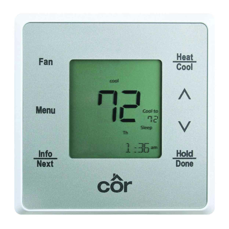
cor thermostat TSTATECM2W01 User manual

TSTATECM2W01
Two-Wire Relay Module
For use with the Côr®7 and
Côr®7C Thermostats
Installation Instructions
Designed in the USA.
NOTE: Read the entire instruction manual before starting the installation.

1
TABLE OF CONTENTS
PAGE
SAFETY CONSIDERATIONS 1................................
INTRODUCTION 2..........................................
INSTALLATION CONSIDERATIONS 3..........................
INSTALLATION 5...........................................
TROUBLESHOOTING 11.....................................
WIRING DIAGRAMS 15−34...................................
SAFETY CONSIDERATIONS
Read and follow manufacturer instructions carefully. Follow all local electrical
codes during installation. All wiring must conform to local and national electrical
codes. Improper wiring or installation may damage Thermostat.
Recognize safety information. This is the safety−alert symbol . When you see
this symbol on the equipment and in the instruction manual, be alert to the potential
for personal injury.
Understand the signal words DANGER, WARNING, and CAUTION. These
words are used with the safety−alert symbol. DANGER identifies the most serious
hazards which will result in severe personal injury or death. WARNING signifies a
hazard which could result in personal injury or death. CAUTION is used to identify
unsafe practices which may result in minor personal injury or product and property
damage. NOTE is used to highlight suggestions which will result in enhanced
installation, reliability, or operation.

2
INTRODUCTION
The Côr Two−Wire Relay Module for use with the Côrr7 and Côrr7C
Thermostats allows installation in homes where there are not sufficient wires to
connect to the equipment and/or the C−wire for thermostat power. The module is
mounted near or on the indoor equipment. The unit communicates to the Côr 7
Series Thermostat through the two wires that carry a combination of power and
communications data that is unique to these products.
This gives greater flexibility to the installer when there are insufficient numbers of
wires at the thermostat wall location. This prevents the installer from having to run
additional thermostat wiring, thus saving on installation time.

3
INSTALLATION CONSIDERATIONS
Power
The Two−Wire Relay Module is powered by 24VAC. Only 2 wires are required for
connection between the Côr 7 Series Thermostat and the Two−Wire Relay Module.
These two wires (V+ and Vg) do not provide ordinary 24VAC. They carry a
combination of power and communications data that is unique to these products.
Humidify Equipment and Connections
The humidify output connects directly to 24VAC operated humidifiers. An isolation
relay may be required when using powered humidifiers. No other connection or
interlock is required. Any of several installer−selectable operating modes are
available.
ELECTRICAL OPERATION HAZARD
Failure to follow this warning could result in personal injury or death.
DO NOT connect furnace HUM terminal directly to Thermostat
Control HUM terminal. This will bypass furnace safety controls. See
Low Voltage Wiring Diagrams and notes for proper connection.
!WARNING
Dehumidify Equipment and Connections
The dry contact output connects to the dehumidify input on variable—speed
furnaces and fan coils. Additional dehumidification is done by controlling the
compressor. A variety of operating modes are available on the Côr 7 Series

4
Thermostats. The dry contact must be configured for dehumidification. See Wiring
Diagrams for more information.
Outdoor Temperature Sensor (TSTATXXSEN01−B)
Outdoor air temperature sensor (OAT) is an optional accessory that will connect to
the Two−Wire Relay Module. Optimum performance is obtained when Wi−Fi
weather is setup or an outdoor temperature sensor is used with the Côr 7 Series
Thermostats. If not using Wi−Fi weather, plan on installing an OAT so that 2 wires
can be run from Equipment Control Module to an outdoor location, preferably on
the north side of the house or near the outdoor equipment. Caution should be used
when selecting the location of the OAT. Direct sunlight or heat from the outdoor
equipment could cause the outdoor temperature at the sensor to be inaccurate. The
sensor can be mounted to outdoor unit and existing control wires may be used for
its connection. Details are provided in sensor instructions.
Remote Indoor Temperature Sensor
A wired remote temperature sensor may be used where it is desirable to install the
Côr 7 Series Thermostat in a limited access location while measuring the
temperature in the living space. The remote room sensor may be used as a
stand−alone or average with local sensor.
Install the Two−Wire Relay Module
Install the Two−Wire Relay Module near or on the cabinet of the indoor furnace or
fan coil. Connection from the Thermostat to the Module requires only two wires.
All other control wires are connected to the Two−Wire Relay Module from the
HVAC equipment.
Wiring
For all wiring applications, use 22 AWG or larger wire. Continuous wire lengths
over 100 ft. (30.5 m) should use 20 AWG or larger. Wire lengths are not to exceed
250 ft. (76 m) per run.

5
INSTALLATION
UNIT DAMAGE HAZARD
Failure to follow the recommended wiring practices could result in
damage to the wall control and personal property.
Improper wiring or installation may damage Thermostat Control.
Check to make sure wiring is correct before proceeding with
installation or turning on power.
CAUTION
!
Installation Notes:
SNever remove the Two−Wire Relay Module board from the plastic hous-
ing. Doing so could warp and damage the components on the board.
SThe Two−Wire Relay Module should be mounted before wires are at-
tached.
SProvide sufficient excess wiring behind the mounting plate. Coil the
wiring, creating a service loop, and place in mounting box or in the
cabinet to remove strain against the terminal strip.

6
Fig. 1 −TSTATECM2W01 Carton Contents
Carton contains the following components.
1. Two−Wire Relay Module
2. Stand−off for Equipment Control Module
3. Plastic anchors and screws
Install Two−Wire Relay Module Control
Follow the installation instructions for installing the Côr 7 Series Thermostat.
ELECTRICAL OPERATION HAZARD
Failure to follow this warning could result in personal injury or death.
Before installing Thermostat Control, turn off all power to
equipment. There may be more than 1 power disconnect.
!WARNING

7
UNIT DAMAGE HAZARD
Failure to follow this caution may result in equipment damage or
improper operation.
Improper wiring or installation may damage Thermostat Control.
Check to make sure wiring is correct before proceeding with
installation or turning on power.
CAUTION
!
1. Turn off all power to equipment.
2. If an existing thermostat is being replaced:
a. Remove existing control from wall.
b. Disconnect wires from existing thermostat, 1 at a time.
c. As each wire is disconnected, record wire color and terminal marking.
d. Discard or recycle old control.
ENVIRONMENTAL HAZARD
Failure to follow this caution may result in environmental damage.
Mercury is a hazardous waste. Federal regulations require that
Mercury be disposed of properly.
CAUTION
!

8
3. Secure thermostat mounting base to wall and make sure all wires extend
through hole in mounting base per the Côr 7 Series installation instructions.
4. Connect two wires to the Vg and V+ terminals on the Côr 7 Series Thermo-
stat, noting their color and which terminal they are attached. Typically the
red wire is V+ and black is Vg.
5. Push any excess wire into wall and against mounting base. Seal hole in wall
to prevent air leaks. Leaks can affect operation and cause incorrect tempera-
ture and/or humidity measurement.
6. Find suitable indoor mounting location for Two−Wire Relay Module, either
near or on the indoor furnace or fan coil equipment. See Fig. 2.
IMPORTANT NOTE: Two−Wire Relay Module should not be mounted to duct
work or below any other controls or equipment (i.e. humidistat, humidifier, etc.).
Fig. 2 −Equipment Control Module on Equipment

9
7. Route wires through rear of Two−Wire Relay Module using either a clear-
ance hole or supplied standoff. See Fig. 3.
Fig. 3 −Standoff
NOTE: Standoffs are provided as an aid when installing Two−Wire Relay Module
on inside equipment or a solid wall.
8. Match and connect equipment wires to proper terminals of each connector
block being careful not to over tighten the screws. Correct polarity must be
observed when connecting the two wires from the Two−Wire Relay Module
to the Côr 7 Series Thermostat mounting base. If wires are connected incor-
rectly, the Thermostat will not operate.
9. Snap cover over top of Two−Wire Relay Module. See Fig. 4.

10
Fig. 4 −Cover on Equipment Control Module
10. Turn on power to equipment. On power up, all display segments will light
for 5 sec. and two digit code appears on the center of the display which
identifies the thermostat equipment type configuration.
Refer to the Côr 7 Series Thermostat installation instructions to set up the
thermostat with the Two−Wire Relay Module.

11
TROUBLESHOOTING
If the display doesn’t power up after power is applied, check the Rc/Rh and C
terminals for 24VAC. If 24VAC is present, check the voltage between Vg and V+.
This voltage will be approximately 12−20VDC. If voltage is present, check the
polarity to make sure it is wired correctly. The display will not power up if polarity
is reversed.
Error Codes
Comm Error −If the Côr 7 Series Thermostat and the Two−Wire Relay Module
cannot communicate via two−wire connection, an Comm Error will be displayed.
HW Failure −If Côr 7 Series Thermostat’s internal memory fails, HW Failure will
be displayed. Replace Thermostat.
Invalid HUM −If Côr 7 Series Thermostat cannot properly read humidity, Invalid
HUM will be displayed. Replace Côr 7 Series Thermostat. If both Humidify and
Dehumidify have been set to OFF, the humidity value will not be shown on the
screen when cycling through the info button.
Table 4 can be used as a troubleshooting tool for determining which outputs will be
active for a particular configuration and each operating mode.

12
IDU ODU Equip-
ment
Type
Options Cool
Stage 1
Cool
Stage 2
Heat
Stage 1
Heat
Stage 2
Heat
Stage 3
Heat
Stage 4
EM
Heat
Stage 1
EM
Heat
Stage 2
1 Stage
Fur-
nace
1 Stage
AC
Opt
1=AC
−− Y/Y2 −− W/W1 −− −− −− −− −−
Fan
Coil 1
Stage
Heat
1 Stage
HP
Opt
1=HP
RVS=
O
Opt
10=C
Y/Y2
O/W2/
B
−− Y/Y2 Y/Y2,
W/W1
−− −− W/W1 −−
Fan
Coil 1
Stage
Heat
1 Stage
HP
Opt
1=HP
RVS=
B
Opt
10=H
Y/Y2 −− Y/Y2
O/W2/
B
Y/Y2,
W/W1,
O/W2/
B
−− −− W/W1 −−
Fan
Coil 1
Stage
Heat
2 Stage
HP
Opt
1=H2
RVS=
O
Opt
10=C
Y1/W2
O/W2/
B
Y1/W2
,
Y/Y2
O/W2/
B
Y1/W2 Y1/W2
, Y/Y2
Y1/W2
,
Y/Y2,
W/W1
−− W/W1 −−
Fan
Coil 1
Stage
Heat
2 Stage
HP
Opt
1=H2
RVS=
B
Opt
10=H
Y1/W2 Y1/W2
, Y/Y2
Y1/W2
,
O/W2/
B
Y1/W2
,
Y/Y2,
O/W2/
B
Y1/W2
, Y/Y2,
W/W1,
O/W2/
B
−− W/W1 −−
Fan
Coil 2
Stage
Heat
1 Stage
HP
Opt
1=HP
RVS=
O
Opt
10=C
Y/Y2
O/W2/
B
−− Y/Y2 Y/Y2,
W/W1
Y/Y2,
W/W1,
Y1/W2
−− W/W1 W/W1,
Y1/W2
Fan
Coil 2
Stage
Heat
1 Stage
HP
Opt
1=HP
RVS=
B
Opt
10=H
Y/Y2 −− Y/Y2
O/W2/
B
Y/Y2,
W/W1,
O/W2/
B
Y/Y2,
W/W1,
Y1/W2
,
O/W2/
B
−− W/W1 W/W1,
Y1/W2

13
IDU ODU Equip-
ment
Type
Options Cool
Stage 1
Cool
Stage 2
Heat
Stage 1
Heat
Stage 2
Heat
Stage 3
Heat
Stage 4
EM
Heat
Stage 1
EM
Heat
Stage 2
Fan
Coil 3
Stage
Heat
1 Stage
HP
Opt
1=HP
RVS=
O
Opt
10=C
Opt
43=On
(3
stage
Heat)
Y/Y2
O/W2/
B
−− Y/Y2 Y/Y2,
W/W1
Y/Y2,
Y1/W2
Y/Y2,
W/W1,
Y1/W2
W/W1 W/W1,
Y1/W2
Fan
Coil 3
Stage
Heat
1 Stage
HP
Opt
1=HP
RVS=
B
Opt
10=H
Opt
43=On
(3
stage
Heat)
Y/Y2 −− Y/Y2
O/W2/
B
Y/Y2,
W/W1,
O/W2/
B
Y/Y2,
Y1/W2
,
O/W2/
B
Y/Y2,
W/W1,
Y1/W2
,O/W2/
B
W/W1 W/W1,
Y1/W2
2 Stage
Fur-
nace
2 Stage
AC
Opt
1=A2
−− Y1/W2 Y1/W2
, Y/Y2
W/W1 W/W1,
O/W2/
B
−− −− −− −−
2 Stage
Fur-
nace
1 Stage
HP
Opt
1=hh
RVS=
O
Opt
10=C
Y/Y2
O/W2/
B
−− Y/Y2 W/W1 W/W1,
Y1/W2
−− W/W1 W/W1,
Y1/W2
2 Stage
Fur-
nace
1 Stage
HP
Opt
1=hh
RVS=
B
Opt
10=H
Y/Y2 −− Y/Y2
O/W2/
B
W/W1 W/W1,
Y1/W2
−− W/W1 W/W1,
Y1/W2
1 Stage
Fur-
nace
2 Stage
HP
Opt
1=h2
RVS=
O
Opt
10=C
Y1/W2
O/W2/
B
Y1/W2
, Y/Y2,
O/W2/
B
Y1/W2 Y1/W2
, Y/Y2
W/W1 −− W/W1 −−
1 Stage
Fur-
nace
2 Stage
HP
Opt
1=h2
RVS=
B
Opt
10=H
Y1/W2 Y1/W2
, Y/Y2
Y1/W2
,
O/W2/
B
Y1/W2
, Y/Y2,
O/W2/
B
W/W1 −− W/W1 −−

14
IDU ODU Equip-
ment
Type
Options Cool
Stage 1
Cool
Stage 2
Heat
Stage 1
Heat
Stage 2
Heat
Stage 3
Heat
Stage 3
EM
Heat
Stage 1
EM
Heat
Stage 2
1 Stage
Fur-
nace
1 Stage
HP
Opt
1=hh
RVS=
O
Opt
10=C
Y/Y2
O/W2/
B
−− Y/Y2 W/W1 −− −− W/W1 −−
1 Stage
Fur-
nace
1 Stage
HP
Opt
1=hh
RVS=
B
Opt
10=H
Y/Y2 −− Y/Y2
O/W2/
B
W/W1 −− −− W/W1 −−
1 Stage
Fur-
nace or
Fan
Coil
No
ODU
Opt
1=H
−− −− −− W/W1 If HP
or RH
board
and
Opt
32−2
W/W1,
O/W2/
B
−− −− −− −−
Air
Han-
dler
1 or 2
Stage
AC
Opt
1=C
−− Y/Y2 Y1/W2
, Y/Y2
2 SPD
only
−− −− −− −− −− −−

15
WIRING DIAGRAMS
* Indicates that connection may not be required/available.
Fig. 5 −Display to Equipment Control Module Connection

16
* Indicates connection may not be required/available.
Fig. 6 −FV/FK Fan Coil with 2−Stage Heat Pump

17
Typical Single-Stage
Fan Coil Heat Pump
O
RVS Cooling O/B W2 E W2
Heat Stage 2 W/W1 W2
Heat Stage 3 Y1 / W2 W3
Heat/Cool Stage 1 Y/Y2 Y
Fan G G
24VAC Hot Heating Rh R R
24VAC Hot Cooling Rc
Dry Contact 1 D1
Dry Contact 2 D2
24VAC Common C C C
Humidify HUM
Outdoor Air Temp OAT
Remote Room Sensor RRS
OAT/RRS Com SRTN
Outdoor Sensor *
Humidifier Solenoid
Valve *
Remote Room
Sensor *
* Indicates connection may not be required/available.
Two-Wire Relay Module
Fig. 7 −Typical Fan Coil with Heat Pump

18
* Indicates connection may not be required/available.
Two-Wire Relay Module
Fig. 8 −Fan Coil Shown w/Aux.Connection #1
(Heat Pump/Air Conditioner removed for clarity.)

19
Fan Coil Air ConditionerTwo-Wire Relay Module
* Indicates connection may not be required/available.
Fig. 9 −FV/FK Fan Coil w/2−Stage Air Conditioner
Table of contents
Other cor thermostat Thermostat manuals