manuals.online logo
Brands
  1. Home
  2. •
  3. Brands
  4. •
  5. Imit
  6. •
  7. Thermostat
  8. •
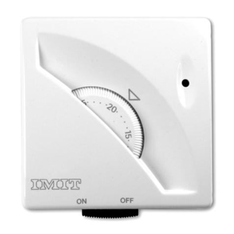
  9. Imit TA3 User manual

Imit TA3 User manual

TA3
uale istruzioni ~I
-technique ~ ßed
leiding ~ Manual de instrucciones
nual de instru~öes ~OÖllYLESXPllQEWS
fig.3
ELK.3
A
c
ON
fig.l - HK.l
44,15 57
79.6
~
@-
~
.,
fig.2 - ELK.2
fig.4
HK.4
fig.5
ELK.5 W
"',.,'"
.. ---'g'
HK.6
.
fig.7 - ELK.7 fig.8 - ELK.8 fig.9 - HK.9
..-"
\
fig.l0 - ECK.l0
ON OFF
fig.12 - ECK.12
ON OFF
fig.ll - ECK.11
fig.13 - ECK.13
fig.14 - ECK.14 fig. 15 - ECK.15
INTRODUZIONE Q)
Laringraziamoper la fiducia che havoluto riservarcie ci complimentiamo con
leiperaverscelto un nostro prodotto. 1Ipresentedispositivo e un TERMOSTATO
MECCANICOsemplice da usare, ehe consente di regolare la temperatura
ambientenelluogo in cui e installato e pertanto e in grado di soddisfare le
esigenzedegli utenti in termini di COMFORTambientale.
CONFORMIT~:Al!~_Ni>BJ-1i:-
- EN60730-'
edaggiornamentisuccessivi
- EN60730-2-9
CONFORMITA'ALLEDIRETTIVE
-B~T73i23T(iE "---
- E.MC.89/336/CEEedaggiornamenti
successivi93/68/CEE
CARATTERISTICHETECNICHE
CAMPODIREGOLAZIONETEMPERATURA~5'~30'C
DIFFERENZIALE~ 0,4K-cO,8K
GRADO DI PROTEZIONE ~ IP 20
CLASSEDIISOLAMENTO~I
GRADIENTETERMICO~1K/15min.
USCITA~contatti in commutazione
PORTATASUICONTATTI~16(2,5)A/250V~
TIPODIAZIONE~1B
GRADODIPOLLUZIONE~2
TEMPERATURA MASSIMA DI SERVIZIO - 50'C
TEMPERATURADISTOCCAGGIO~O'-c50'C
MONTAGGIO - a parete
TENSIONE NOMINALE D'IMPUlSO ~ 4KV
IlEGENDACOMANDIDEl TERMOSTATO
A~Manopolaimpostazionetemperatura (fig.l)
B~led (secondoi modelli)
C~InterruttoreON/OFF0commutatoreEstate/lnverno(secondoi modelli)
ACCESSORIA RICHIESTA
.Accessorio sottobase -cod. 004095 (fig.3)
.Accessorioperlimite dei campodi regolazione
0 blocco della temperatura impostata ~cod.000071(fig.4)
INSTAlLAZIONEECOllEGAMENTI f!l
Lt.PRESCßIZIONID!2.ICUREZ~ :_--
Primadi collegareil termostato accertarsiehela tensionedi alimentazione dei
CARICOUTILIZZATOREda comandare (caldaia, pompa, impianto di condi-
zionamento ecc.)NONSIA COlLEGATAe che corrisponda a quella riportata
all'internodell'apparecchio(250V~ max).(fig.5)
POSIZIONAMENTO --. -.--.-.--
Installare il termostato lontano da fonti di calore (caloriferl, raggi solari,
cucine)eda porte/finestre, a circa 1,5mt dal pavimento. (fig.G)
INSTALLAZIONE i:C°l!.E..§_~~i:NTIJlJ:ITBIQ .
A)In casodi installazione su scatola tonda interasseGOmm,su superficie non
perfettamentepiana0 in altri casi particolari, utllizzare I'accessoriosottobase
(vederecapitolo "Accessoria richiesta").Fissarlomediante unacoppladi forl
adeccezionedi B-B,previstl per il termostato. (fig.7)
B)Separarela basedal coperchio dei prodotto facendo pressionesull'apposito
dentedi aggancio(fig.8), quindi fissarla alla parete (0 alla sottobase)utiliz-
zandoi fori a disposizione(fig.9) a mezzoviti con un diametro max 3,5mm.
C)Portareifili dell'impiantoattraversolaferitoia praticatasullabaseedeseguire
gli allacciamentiallamorsettierain conformita allo schemaelettrico riportato
all'internodeiprodotto; riagganciareIIcoperchioalla base.(fig.l0)
Lt.ATTENZIONE:
SIraccomandadi eseguireI'installazionedei termostato rispettando scrupolo-
samentele normedi sicurezzae ledisposizionl di leggevigenti.
INTRODUCTION @
Thankyou for your confidence in our Companyand for choosing oneof our
products. This is an easy-to-use MECHANICAl THERMOSTAT.It allows an
accurate room temperature adjustment in the hosting room, thus meeting
any users' needsasfar as room comfor!.
CQ~FQß}""I1IIQJ!:IU:ffit!Q.i\IiD?
Thisproductcomplieswith:
- EN60730-'andsubsequent
revisions
- EN60730-2-9
CONFORMITYTOTHEGUIDELINES
--"-' "---" '-'---"-"-"
This product complies with:
- BT 73/23/EEC
- E.MC.89/336/EEC
and later updating of 93/68/EEC
TECHNICAlDATA
TEMPERATURERANGE~5'-c30'C
TEMPERATUREDIFFERENTIAL~ 0,4K-cO,8K
DEGREE OF PROTECTION -IP 20
INSULATIONCLASS~I
TEMPERATURERATEOFCHANGE
~1K/15min.
OUTPUT~switching contacts
CONTACTSRATING~16(2,5)A/250V~
SWITCHACTION- 1B
POLLUTIONDEGREE- 2
MAXIMUM STANDINGTEMPERATURE- 50'C
STORAGETEMPERATURE- O'-c50'C
MOUNTING- to the wall
RATEDIMPULSEVOlTAGE-4KV
THERMOSTATCONTROlKEYS
A-Temperaturesetting knob (fig.l)
B-Warning lamp
C~ON/OFFswitch or SUMMER/WINTERswitch (dependingon models)
OPTIONAlACCESSORIES
.Sub-basefitting -cod. 004095(fig.3)
.Specialfitting for temperaturerangerestrietionsorforthe
temperature lock at apre-set value. -cod.000071(fig.4)
INSTALLATIONANDCONNECTIONS ~
4~~FJD'JN~IßU.cIIQI':!~ ,-- , -'.- ___"M" -
Before connecting the thermostat, makesurethat the supply voltage of the
UNITTOBECONTROlLED(boiler, pump, air-conditioning system, etc.) is NOT
CONNECTEDand that it matches the indication given inside the appliance
(250V~ maxI.(fig.S)
PLACEMENT OF THE THERMOSTAT
'-'---'--""'-"""-'--'-""'-'-'-'---' '-'---------..
Install the thermostat away from heat sources(radiators,sumays,and kitchens)
and away from doors/windows, at approx. 1,5m height from the floor. (fig.G)
!1':!.~I~_L!ATL°..N.l\Ng,_~!B~§SONN~fIl9..N~___-----_.__.
A) In case the thermostat shall be installed either in a round built-in box
(havingdistancebetweencentresequalto 60mm),or on an unevenwall surface
or in other particular locations, it is recommended to use a sub-base fitting
(seeparagraph "Optional Accessories"). Fixthe fitting to the wall through two
holes other than the ones marked as B-B, which are exclusively provided for
the thermostat installation. (fig.7)
B)Removethe front cover from the thermostat baseby releasingthe provided
clip (fig.8), then fix it to the wall (or to the sub.base fitting) through the
provided holes(fig.9) and tighten it by means of suitable screwshaving max
of 3,5mm.
C)Threadthe power supply wires through the slot in the baseand connect
them to the terminals asper the wiring diagram sketchedinsidethe appliance.
Snap the front cover back.(fig.l0)
LhWARNING:
It is recommendedto install the appliancestrictly in compliancewith allsafety
and law provisions in force.
PRESENTATION @
Nous vous remercionspour laconfiance que vous nousavezaccordeeet nous
vous felicitons,d'avoir choisiI'un de nosproduits. Ceproduit est un thermostat
d'ambiance MECANIQUEutilisant la technologie "diastat a expansionde vapeur
saturee". II permet de reguler, avec une extreme precision, la temperature
ambiante du lieu ou il est installe et est donc apte a satisfaire lesutilisateurs
les plus exigeants en terme de CONFORT.
CONFORMITE AUX NORM ES CONFORMITE AUX DIRECTIVES
=EN6073cNeiles-;;;~- .:ßI73!23/CEE '
ajour suivantes - E.M.C.89/336/CEE
- EN60730-2-9 etmisesajourssuivantes93/68/CEE
CARACTERISTIQUESTECHNIQUES
PLAGEDEREGLAGEDELATEMPERATURE~S'~30'C
DIFFERENTIEL~ 0,4K.,.0,8K
DEGREDEPROTECTION~ IP20
CLASSED'ISOLATION~ I
GRADIENTTHERMIQUE~ 1K/l Smin.
SORTIERELAIS~contact inverseur libre de potentiel
POUVOIRDECOUPURE~ 16(2,S)A/2S0V~
TYPED'ACTION~1B
DEGREDEPOLLUTION~2
TEMPERATUREMAXIMALEDEFONCTIONNEMENT~ SO'C
TEMPERATUREDESTOCKAGE~ O'.,.SO'C
FIXATION~ murale
TENSIONNOMINALED'IMPULSION~ 4KV
COMMANDESDUTHERMOSTATD'AMBIANCE
A-Bouton de reglagede la temperature (fig.l)
B~Voyant(seionlesmodeles)
C~InterrupteurON/OFFoucommutateurETE/HIVER(seionlesmodeles)
ACCESSOIRESENOPTION
.Soeleadaptateur ~cod 004095 (fig.3)
.Cavalierspour la limitation ou le blocage de la plage
detemperature~cod.000071(fig.4)
INSTALLATION [!1
~PRECAUTIONS D'INS!t\L~!!91L___.._._--_._._...__.._-
Avant deraccorder lethermostat d'ambiance,assurez-vousque I'alimentation
electrique de la CHARGEA CONNECTER(chaudiere, pampe,climatiseur, etc.)
ESTCOUPEE.Contrölerque latension d'alimentation correspondacelle indiquee
a I'inkrieur de I'appareil (2S0V~max.).(fig.5)
CHOIX DE L'EMPLACEMENT .-----.--.--.
Installerle thermostat d'ambiance loin de taute sourcede chaleur (radiateurs,
rayonnementssolaires,cuisinieres)et desporteset fenetres(aenviron 1,50m du
sol).(fig.6)
MISE.Ef:J..f1ACE.lLI3.~f.Q.RJ:>tM.El'JL~hEQ~(1..\Jt._.,-_._-
AI En cas d'installation sur une boite encastree diametre 60 mm, sur une
surface qui n'est pas parfaitement plane ou pour d'autres cas particuliers,
utiliser I'accessoire "socle adaptateur" (voir le paragraphe accessoire
en option). Lafixation du socleadaptateur sur le mur s'effectue a I'aide de
2 vis. IIest important de laisserlibre lestrous B-B, qui sont prevus pour la
fixation du thermostat sur le soeleadaptateur. (fig.7)
B)Separerle soeledu couvercleen effectuant, a I'aided'un tournevis,
une legerepressionsur les clips en plastique (fig.8). Utiliser lesvis a votre
disposition (fig.9) (d'un diametre maximum de 3,Smm) pour fixer
lethermostat sur lemur ou sur lesoeleuniversei en option.
CIPasserle cäblea travers lesocle,par le trau prevu a cet effet, puis raccorder
lesfils surlesbornesen respectant leschemade raccordementqui setrouve
surle socledu thermostat.
Remettrelecouvercle du thermostat sur lesocle.(fig.l0)
LhATTENTION:
11est recommande d'installer le thermostat d'ambiance programmable en
respectantscrupuleusementlesnormes desecuriteet la legislationenvigueur.
"-
EINLEITUNG @'-
Wir danken Ihnen für das uns entgegengebrachte Vertrauen und
beglückwünschenSiezur WahleinesunsererProdukte.DasvorliegendeProdukt
ist ein einfach einzusetzenderMECHANISCHERTHERMOSTAT,dereine Regelung
der Raumtemperatur am Installationsort ermöglicht und deshalb in der Lage
ist,die BedürfnissedesKundenhinsichtlichdesRAUMKOMFORTSzu befriedigen.
ÜBEREINSTIMMUNG
!'!11LP_E~'yQß.S~tiR1BJH:....
- EN60730-1undfolgende
Ergänzungen
- EN60730-2-9
ÜBEREINSTIMMUNG
MIT DENRICHTLINIEN:
="BT73/23jfivr:;"-' '--
- E.M.C.89/336/EWGund folgende
Ergänzungen93/68/EWG
TECHNISCHEEIGENSCHAFTEN
TEMPERATUREINSTELLBEREICH~ S".,.30'C
DIFFERENTIAL = 0,4K.,.0,8K
SCHUTZGRAD ~ IP 20
ISOLIERKLASSE~I
TEMPERATURGRADIENT = 1K/l Smin.
AUSGANG~Wechselkontakte
KONTAKTLEISTUNG~16(2,S)A/2S0V~
WIRKUNGSART= 1B
VERSCHMUTZUNGSGRAD~2
MAX.BETRIEBSTEMPERATUR~ SO'C
LAGERTEMPERATUR = O'.,.SO'C
MONTAGE ~ an der Wand
IMPULSSPANNUNG~4KV
lEGENDETHERMOSTATSTEUERUNG
A~Temperatureinstellknopf (Abb.l)
B~Kontrolleuchte
C~ON/OFF-SchalteroderSOMMER7WINTER-UmschalterUenachModell)
ZUBEHÖRAUFANFRAGE
.Untersatz ~code004095 (Abb.3)
.Zubehör zur Begrenzung desEinstellbereichsoder zur
Blockierung der eingestellten Temperatur ~code000071 (Abb.4)
INSTALLATIONUNDANSCHlÜSSE [!]
6_~!Cl:I~R!:I~T.~~QB~!:IR1E!tN , , .
Vor dem Anschluß des Thermostats ist zu überprüfen, daß die
Versorgungsspannung des zu steuernden ABNEHMERS (Boiler, Pumpe,
Klimaanlage, usw.) NICHTANGESCHLOSSENISTund daß dieseden Angaben
im Inneren desGerätes(2S0V~ maxI entspricht (Abb. 5)
P.9~IlIQ.~~B~fiG_._._._._._..._._._.._.._..._--------------
DasThermostatfern von Wärmequellen(Heizungsanlage,Sonnestrahlen,Küchen)
sowie Türen / Fenstern und etwa 1,5 m vom Fußbodeninstallieren. (Abb.6)
!N~T.i\LLATIQti_~ti[)_El~KI.R1SIIjE_~f'§f.!:I1Q~~~_- ""' "--
A) BeieinerInstallation auf einemrunden Gehäusemit einemAchsabstandvon
60mm, auf nicht vollständig ebenenFlächenoder in anderenSonderfälle,den
Untersatzverwenden (sieheKapitel"Zubehörauf Anfrage").Diesesmittels ein
paarBohrungenaußerB-Bbefestigen,diefür dasThermostatvorgesehensind.(Abb.7)
B)DasUnterteilvom DeckeldesProduktesdurch Druckauf denentsprechenden
Hakenlösen(Abb.8), dann diesesan der Wand (oderam Untersatz)mit Hilfe
derzurVerfügungstehendenBohrungen(Abb.9) mittels Schraubenmit einem
max.Durchmesservon 3,Smmbefestigen.
C)DieKabelderAnlageüberdenim UnterteilvorhandenenKabelschlitzeinführen
und dieAnschlüssean dieKlemmleistegemäßdemSchaltplanim Innerendes
Produktesausführen.DenDeckelwiederauf dasUnterteil aufsetzen.(Abb.lD)
..:::hACHTUNG:
Eswird empfohlen,dieInstallationdesThermostatsuntergenauerEinhaltungder
SicherheitsvorschriftenunddergültigengesetzlichenBestimmungenvorzunehmen.
Other manuals for TA3

1

Other Imit Thermostat manuals

Imit Duo Plus User manual

Imit

Imit Duo Plus User manual

Imit TA3 User manual

Imit

Imit TA3 User manual

Imit SILVER CR S User manual

Imit

Imit SILVER CR S User manual

Imit WPT R User manual

Imit

Imit WPT R User manual

Imit 6007548 User manual

Imit

Imit 6007548 User manual

Imit WPT OT SL User manual

Imit

Imit WPT OT SL User manual

Imit Chronomix S User manual

Imit

Imit Chronomix S User manual

Imit SILVER TA/RF S User manual

Imit

Imit SILVER TA/RF S User manual

Imit Chronomix S User manual

Imit

Imit Chronomix S User manual

Imit CRX/E Plus User manual

Imit

Imit CRX/E Plus User manual

Imit orion DAY/WEEK User manual

Imit

Imit orion DAY/WEEK User manual

Imit TECHNO RT User manual

Imit

Imit TECHNO RT User manual

Imit WPTT User manual

Imit

Imit WPTT User manual

Imit TECHNO DUO User manual

Imit

Imit TECHNO DUO User manual

Imit ETR User manual

Imit

Imit ETR User manual

Imit TECHNO DPT User manual

Imit

Imit TECHNO DPT User manual

Imit TECHNO WPT User manual

Imit

Imit TECHNO WPT User manual

Popular Thermostat manuals by other brands

Honeywell RTH221 Series user guide

Honeywell

Honeywell RTH221 Series user guide

Heatmiser PRT-TS WiFi user manual

Heatmiser

Heatmiser PRT-TS WiFi user manual

Vimar Eikon 20514 quick start guide

Vimar

Vimar Eikon 20514 quick start guide

Honeywell TB7600 installation instructions

Honeywell

Honeywell TB7600 installation instructions

EWT CLIMA 903TLS manual

EWT

EWT CLIMA 903TLS manual

HeatMat HC10 user guide

HeatMat

HeatMat HC10 user guide

Rickard MLM RF operating manual

Rickard

Rickard MLM RF operating manual

Center EHE0200364 installation guide

Center

Center EHE0200364 installation guide

GE Security IS-ZW-TSTAT-100 Operation guide

GE Security

GE Security IS-ZW-TSTAT-100 Operation guide

DIGITEN WTC200 user manual

DIGITEN

DIGITEN WTC200 user manual

Vive Comfort TP-N-601 installation manual

Vive Comfort

Vive Comfort TP-N-601 installation manual

Carrier Connect 33CONNECTSTAT43 installation guide

Carrier

Carrier Connect 33CONNECTSTAT43 installation guide

Maico TH 10 Mounting and operating instructions

Maico

Maico TH 10 Mounting and operating instructions

Havaco HTS User manual and warranty

Havaco

Havaco HTS User manual and warranty

LEGRAND 6830 31 user manual

LEGRAND

LEGRAND 6830 31 user manual

White Rodgers 1F79 installation instructions

White Rodgers

White Rodgers 1F79 installation instructions

BMR VTM3000 User and service manual

BMR

BMR VTM3000 User and service manual

Venstar ColorTouch T6900 Owner's manual and installation instructions

Venstar

Venstar ColorTouch T6900 Owner's manual and installation instructions

manuals.online logo
manuals.online logoBrands
  • About & Mission
  • Contact us
  • Privacy Policy
  • Terms and Conditions

Copyright 2025 Manuals.Online. All Rights Reserved.