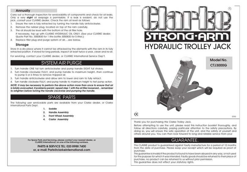
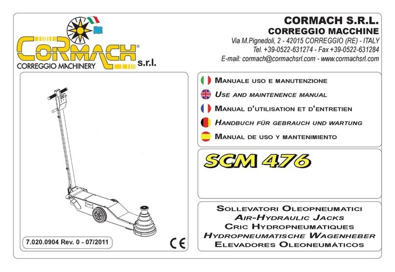
Cormach SCM 230 User manual

7.020.0903 Rev. 0 - 07/2011
Manuale uso emanutenzione
Use and maintenence manual
Manual d’utilisation et d’entretien
Handbuch für gebrauch und wartung
Manual de uso ymantenimiento
sollevatori oleopneumatici
air-hydraulic Jacks
cric Hydropneumatiques
hydropneumatische wagenheber
elevadores oleoneumáticos
CORMACH S.R.L.
CORREGGIO MACCHINE
Via M.Pignedoli, 2 - 42015 CORREGGIO (RE) - ITALY
Tel. +39-0522-631274 - Fax +39-0522-631284


Via M. Pignedoli, 2 - 42015 CORREGGIO (R.E.) ITALY
Tel. +39-0522-631274 - Fax +39-0522-631284
www.cormachsrl.com
Correggio li, 10.01.2010
Rev.4 del 10-01-2010
DECLARATION OF CONFORMITY
We, CORMACH S.r.l.,
hereby declare under our own responsa-
bility that the machine named below con-
form to the Machinery Directive 2006/42/
CE and subsequent amendments and with
European Norm EN 1494 of November
2000.
DÉCLARATION DE CONFORMITÉ
Nous, CORMACH S.r.l.,
déclarons sous notre seule responsabi-
lité que la machine désignée ci-après est
conforme aux
Directive Machines 2006/42/CE et modi-
-
ropéenne EN 1494 de Novembre 2000.
KONFORMITÄTSERKLÄRUNG
gemäß Richtlinien 2006/42/CE und nachfolgenden Änderungen
Erklären wir, CORMACH S.r.l.
hiermit auf unsere Verantwortung, dass die
Maschine unten genannten
Es entspricht der Maschinenrichtlinie
2006/42/CE und nachfolgender Änderun-
gen sowie der Europäischen Norm EN
1494 vom November 2000 entsprechen.
DECLARACIÓN DE CONFORMIDAD
Nosotros, CORMACH S.r.l.
declaramos bajo responsabilidad propria
que la máquina se enumeran a continua-
2006/42/CE-
nes y por la Norma Europea EN 1494 de
noviembre de 2000.
DICHIARAZIONE DI CONFORMITA’
Noi, CORMACH S.r.l.
che la macchina sotto indicata
risulta conforme alla Direttiva Macchine
2006/42/CE-
EN 1494 del
Novembre 2000.
Type / Serial number / Year of construction
Type / Numéro de série / Année de construction
Typ / Seriennummer / Baujahr
La persona giuridica autorizzata a costituire il fascicolo tecnico della costuzione è: Sig.ra Grazia IORI c/o CORMACH s.r.l.
Via M. Pignedoli, 2 - 42015 Correggio (RE) - Italia

Cod. 7.020.0903 - Rev. 07/11
4

Cod. 7.020.0903 - Rev. 07/11
SIMBOLI SYMBOLS SYMBOLES ZEICHEN SIMBOLOS
VIETATO! FORBIDDEN! PROHIBE! VERBOTEN! PROHIB ID O!
Indossare guanti da lavoro Wear work gloves Portar des gants de travail Der Arbeit ange messene
Handschuhe tragen Llevar guantes de trabajo
Wear work shoes Mettre des chaussures de
travail
Der Arbeit angemessene
Shuhe tragen
Indossare occhiali di
Wear safety goggles Portar des lunettes de
sécurité Schutzbrille tragen
Colocarse gafas de
seguridad
Wear safety earcaps Portar un casque de
securite' Schutzkopfhorer tragen Colocarse gorras de
seguridad
Pericolo di scariche
elettriche Shock hazard Danger d'électrocution Gefahr: elektrische
Entladungen Peligro descargas elèctricas
Caution: hanging loads Attention: charges
suspendues Achtung hängende Lasten Atenciòn cargas
suspendidas
organi meccanici in
movimento
Danger! Moving mechanical
parts
Danger! Organes
mécaniques en mouvement
Gefahrt! Bewegliche
mechanische Organe
Peligro! Partes mecanicas
en movimlento
Pericolo di schiacciamento Crushing danger Risque d'ecrasement Gefahrt! Quetschgefahr Peligros de aplastamiento
interventi da eseguire
obbligatoriamente
Mandatory. Operations or
jobs to be performed
compulsorily
Obligation. Operations ou
interventions a realiser
obligatoirement
Pflicht. Obligatorisch
auszuführende
Arbeitsvorgänge oder
Eingriffe
intervenciones que hay que
Pericolo! Prestare
Danger! Be particulary
careful Danger! Faire trés attention Gefahrt! Äusserste Vorsicht
ist geboten
Peligro! Prestare special
elevatore o transpallet
Move with fork lift truck or
transpallet
Déplacement avec chariot
élévateur ou transpallet
Transport mit Gabelstapler
oder Handgabelhub-wagen
carretilla elevadora o
transpallet
Sollevamento dall'alto Lift from above Levage par le haut Anheben von oben Elevaciòn desde arriba
SIMBOLOGIA UTILIZ-
ZATA NEL MANUALE
SYMBOLS USED IN
THE MANUAL
SYMBOLES UTILISÉS
DANS LA NOTICE
IN DER BEDIE-
NUNGSANLEITUNG
VERWENDETE ZEICHEN
SIMBOLOGÍA UTILIZADA
EN EL MANUAL
5

Cod. 7.020.0903 - Rev. 07/11
ATTENZIONE!
Il presente manuale costituisce
parte integrante del prodotto.
Dovrà seguire tutta la vita
operativa del sollevatore.
Conservarlo, quindi in un luogo
noto e facilmente accessibile
e consultarlo ogni qualvolta
sorgano dubbi.
Tutti gli operatori al prodotto
devono poter leggere il manuale.
Ogni danno derivante dalla
mancata osservanza delle
indicazioni contenute nel
presente libretto non sarà
addebitabile al costruttore ed
esime la CORMACH S.r.l. da ogni
responsabilità.
WARNING! ATTENTION! ACHTUNG! ¡ATENCIÓN!
This manual is an integral part
of the product and must be kept
together with the crosspiece
throughout the lifetime of the lift.
It should therefore be kept in an
easily accessible and familiar
place and consulted when in
doubt.
All product operators must
be able to read the manual.
Any damages resulting from
improper use of the lift and lack
of observation of the instructions
contained in this manual cannot
be charged to the manufacturer
and will release CORMACH S.r.l.
from any liability.
La présente notice est partie
intégrante du produit. Elle
devra accompagner le produit
pendant toute la durée du
fonctionnement. Elle doit donc
être conservée dans un endroit
connu et facilement accessible
et être consultée toutes les fois
qu’un doute se présente.
Tous les opérateurs qui utilisent
le pont doivent pouvoir lire la
notice.
Tout dommage provoqué par
le non respect des instructions
contenues dans la présente
notice ou par une utilisation
incorrecte décline la Société
CORMACH S.r.l. de toute
responsabilité.
Diese Anleitung ist ergänzender
Bestandteil des Produktes. Die
Anleitung in einem bekannten
und leicht zugänglichen Ort
aufbewahren und bei Bedarf
zu Rate ziehen. Alle Bediener
des Produktes müssen zwecks
Einsichtnahme Zugang zur
Anleitung haben.
Alle Schäden, die auf
Nichtbeachtung derAnweisungen
dieser Anleitung oder auf einen
unsachgemässen Betrieb der
Hebebühne zurückzuführen
sind, sind nicht dem Hersteller
anzulasten und befreien die
Firma CORMACH S.r.l. von
jeglicher Haftungspicht.
El presente manual constituye
una parte integrante del
producto. Tendrá que acompañar
el producto durante todo su
funcionamiento. Conservarlo por
lo tanto en un sitio que conozcan
todos, al que se pueda acceder
con facilidad, y consultarlo cada
vez que surjan dudas.
Todas las personas que utilizan
el elevador tienen que poder leer
el manual. Cualquier daño que
derive de la falta de respeto de
las indicaciones que contiene el
presente manual exime de toda
responsabilidad a CORMACH
S.r.l.
COMPOSIZIONE DEL MA-
NUALE
COMPOSITION OF
MANUAL
COMPOSITION DE LA
NOTICE
ZUSAMMENSETZUNG
DER ANLEITUNG
COMPOSICIÓN DEL
MANUAL
56 pagine (copertine comprese)
51 pagine numerate
4 pagine in bianco
1 schema
23 gure
3 tavole ricambi
1 dichiarazione di conformità
CE
56 pages (including cover pages)
51 numbered pages
4 blank pages
1 diagram
23 gures
3 spare parts tables
1 EC declaration of conformity
56 pages (pages de la couverture
incluses)
51 pages numérotées
4 pages blanche
1 schéma
23 gures
3 planches des pièces de
rechange
1 Déclaration de conformitè CE
56 Seiten (inkl. Deckblätter)
51 numerierte Seiten
4 Leere Seiten
1 Schaltpläne
23 Abbildungen
3 Ersatzteiltabellen
1 Konformitätserklärung
56 páginas (incluidas las
cubiertas)
51 páginas numeradas
4 páginas en blanco
1 esquema
23 guras
3 tablas repuestos
1 Declaration de conformitad
6

Cod. 7.020.0903 - Rev. 07/11
SOMMARIO
1 -PRESENTAZIONE
2 -DATI DI TARGA
3 -CARATTERISTICHE TECNICHE
3.1 - DATI TECNICI
3.2 -DIMENSIONI
3.3 -SCHEMA OLEOPNEUMATICO
4 -NORME DI SICUREZZA
5 -DISPOSITIVI DI SICUREZZA
6 -TRASPORTO
7 -DISIMBALLO
8 -INSTALLAZIONE
8.1 - MESSA IN SERVIZIO
8.2 - ALLACCIAMENTO PNEUMATICO
9 -PARTI FUNZIONALI
10 -SEGNALAZIONI ED AVVERTENZE
11 -IDENTIFICAZIONE DEI COMANDI
12 -POSIZIONE DI LAVORO
13 -CONTROLLO CORRETTO FUNZION.
14 -USO
14.1-USO DEL SOLLEVATORE
14.2-SALITA/DISCESA/ARRESTO
15 -MANUTENZIONE
16 -INCONVENIENTI/CAUSE/RIMEDI
17 -ACCANTONAMENTO
18 -ROTTAMAZIONE
19 -GARANZIA
20 -ACCESSORI
20.1-USO DEGLI ACCESSORI
21 -PARTI DI RICAMBIO
21.1-GRUPPO TELAIO
21.2-GRUPPO POMPA/PIASTRA
21.3-GRUPPO CILINDRO SCM230
INDEX
1 -PRESENTATION
2 -DATA ON SERIAL PLATE
3 -TECHNICAL DATA
3.1 - TECHNICAL DATA
3.2 -DIMENSIONS
3.3 -AIR-HYDRAULIC DIAGRAM
4 -GENERAL SAFETY REGULATION
5 -SAFETY DEVICES
6 -TRANSPORT
7 -UNPACKING
8 -INSTALLATION
8.1 -COMMISSIONING
8.2 - PNEUMATIC CONNECTION
9 -FUNCTIONAL PARTS
10 -SIGNS AND WARNING
11 -IDENTIFICATION OF CONTROL
12 -WORKING POSITION
13 -CORRECT OPERATION CHECK
14 -OPERATION
14.1-USING THE JACK
14.2-LIFTING/LOWERING/STOPPING
15 -MAINTENANCE
16 -TROUBLE SHOOTING
17 -STORING
18 -SCRAPPING A MACHINE
19 -WARRANTY
20 -ACCESSORIES
20.1-USING THE ACCESSORIES
21 -SPARE PARTS
21.1-FRAME ASSEMBLY
21.2-
PUMP/PLATE ASSEMBLY
21.3-CYLINDER ASSEMBLY SCM230
SOMMAIRE
1 -PRESENTATION
2 -PLAQUE SIGNALETIQUE
3 -CARACTERIST. TECHNIQUES
3.1 - CARACTERISTIQUES TECHNIQUES
3.2 -DIMENSIONS
3.3 -SCHEMA HYDROPNEUMATIQUE
4 -NORMES DE SECURITE
5 -DISPOSITIFS DE SECURITE
6 -TRANSPORT
7 -DEBALLAGE
8 -INSTALLATION
8.1 - MISE EN SERVICE
8.2 - RACCORDEMENT PNEUMATIQUE
9 -PIECES FONCIONNELLES
10 -SIGNALATIONS ET
AVERTISSEMENT
11 -
IDENTIFICATION DES COMMANDES
12 -POSITION DE TRAVAIL
13 -CONTROLE DU BON FONCTIONN.
14 -UTILISATION
14.1-UTILISATION DU CRIC
14.2-MONTEE/DESCENTE/ARRET
15 -ENTRETIEN
16 -INCONV./CAUSES/REMEDES
17 -REMISAGE
18 -MISE A DECHARGE
19 -GARANTIE
20 -ACCESSOIRES
20.1-UTILISATION DES ACCESSOIRES
21 -PIECES DE RECHANGE
21.1-GROUPE CHASSIS
21.2-GROUPE POMPE/PLAQUE
21.3-GROUPE CYLINDRE SCM230
INHALT
1 -VORBEMERKUNG
2 -DATEN DES TYPENSCHILDS
3 -TECHNISCHE DATEN
3.1 - TECHNISCHE DATEN
3.2 -ABMESSUNGEN
3.3 -HYDROPNEUMATISCHE SCHEMA
4 -SICHERHEITVORSCHRIFTEN
5 -SICHERHEITSVORRICHTUNGEN
6 -TRANSPORT
7 -AUSPACKEN
8 -INSTALLATION
8.1 -INBETRIEBNAHME
8.2 - PNEUMATISCHE ANSCHLUß
9 -HAUPTKOMPONENTEN
10 -BENUTZUNGS UND
GEFAHRENHINWEISE
11 -
KENNZEICHNUNG DER
BEDIENUNGSEL
12 -ARBEITSPOSITION
13 -PRÜFUNG AUF KORREKTEN
BETRIEB
14 -BENUTZUNG
14.1-GEBRAUCH DES WAGENHEBERS
14.2-HEBEN/SENKEN/UNMITTELBARER
15 -WARTUNG
16 -FEHLERSUCHE
17 -LAGERHALTUNG
18 -VERSCHROTTEN
19 -GARANTIE
20 -ZUBEHÖR
20.1-GEBRAUCH DES ZUBEHÖRS
21 -ERSATZTEILE
21.1-RAHMEN
21.2-
PUMPE / PLATTE
21.3-ZYLINDER SCM230
ÍNDICE
1 -PRESENTACIÓN
2 -DATOS DE MATRICULA
3 -CARACTERISTICAS TECNICAS
3.1 -DATOS TÉCNICOS
3.2 -DIMENSIONES
3.3 -ESQUEMA OLEONEUMATICO
4 -NORMAS DE SECURIDAD
5 -DISPOSITIVOS DE SECURIDAD
6 -TRANSPORTE
7 -DESEMBALAJE
8 -INSTALACION
8.1 - PUESTA EN SERVICIO
8.2 -CONEXION NEUMATICA
9 -PARTES FUNCIONALES
10 -SEÑALES Y ADVERTENCIAS
11 -IDENDIFICACION DE COMANDOS
12 -POSICION DE TRABAJO
13 -CONTROL DE CORRECTO
FUNCIONAMIENTO
14 -UTILIZACION
14.1-USO DEL ELEVADOR
14.2-SUBIDA/BAJADA/PARADA
15 -MANTENIMIENTO
16 -PROBLEMAS/CAUSAS/
REMEDIOS
17 -ALMACENADO
18 -DESGUACE
19 -GARANTIA
20 -ACCESSORIOS
20.1-USO DE LOS ACCESORIOS
21 -PIEZAS DE REPUESTO
21.1-GRUPO BASTIDOR
21.2-GRUPO BOMBA/PLACA
21.3-GRUPO CILINDRO SCM230
8 / 9
8 / 9
8 / 9
10 / 11
12 / 13
12 / 13
14 / 15
16 / 19
18 / 19
18 / 19
20 / 21
20 / 21
22 / 23
24 / 25
26 / 27
26 / 27
28 / 29
28 / 29
28 / 29
28 / 31
30 / 33
32 / 35
36 / 39
38 / 41
40 / 41
42 / 43
42 / 43
44 / 45
44 / 45
46 / 47
48 / 51
52 / 53
54 / 55
56 / 57
58 / 59
60 / 61
62 / 63
7

Cod. 7.020.0903 - Rev. 07/11
1 PRESENTAZIONE 1 PRESENTATION
Gentile Cliente,
-
-
tare la ruota del veicolo.
è INDISPENSABILE leggere e capire quanto riportato su
Il Costruttore non può essere ritenuto responsabile di
CONSERVARE CON CURA QUESTO MANUALE PER
OGNI ULTERIORE CONSULTAZIONE.
2 DATI DI TARGA 2 DATA ON SERIAL PLATE
cicli di sollevamento considerando una durata di vita di 10
3
CARATTERISTICHE TECNICHE
3 TECHNICAL DATA
8
Dear Customer,
This instruction manual constitutes an essential part of the
product itself and is intended to inform the operator about
the fundamental rules and criteria to be adopted when using
and maintaining the jack.
Air-hydraulic jacks are constructed to partially lift vehicles,
for the sole purpose of removing/replacing wheels.
Any other use is improper and therefore not authorized.
Before beginning any kind of work on or with this machine,
carefully read and understand the contents of these ope-
rating instructions.
The Manufacturer shall not liable for any injury to per-
sons or damage to things caused by improper use of this
machine.
KEEP THIS MANUAL NEAR THE MACHINE AND CON-
SULT IT AS NEEDED DURING OPERATIONS.
When designing the jack, for the purposes of verication of
the device’s fatigue life (structural mechanical strength) a
fatigue life of 200,000 (two hundred thousand) lifting cycles
was assumed. Considering a lifetime of 10 (ten) years, this
corresponds to a maximum of 50 - 100 (fty - one hundred)
lifting cycles per day.
A- Dati del costruttore
B
C- Modello della macchina
D- Numero di serie della macchina
E
F- Carico massimo di sollevamento
G - Pressione di lavoro in BAR e P.S.I.
The right-hand side of the jack is tted with a nameplate
(g.2/1) with the following identication data:
A- Manufacturer’s name and address
B- CE mark (conforms to the Machinery Directive
2006/42CE)
C- Machine model
D- Machine serial number
E- Year of construction
F- Maximum operating load
G- Operating air pressure in BAR and P.S.I.
2/1
C A B
G F E
D

Cod. 7.020.0903 - Rev. 07/11
1 PRESENTATION 1 VORBEMERKUNG 1 PRESENTACION
2 PLAQUE SIGNALETIQUE 2 DATEN DES TYPENSCHILDS 2 DATOS DE MATRICULA
3
CARACTERISTICAS TECNICAS
3 TECHNISCHE DATEN3
CARACTERISTIQUES TECHNIQUES
9
Cher Client,
Les crics oléopneumatiques ont été conçus comme moyen
de levage partiel dans le seul but de la dépose/repose de
la roue du véhicule.
Toute autre utilisation est considérée impropre et par
conséquent non autorisée.
-
SABLE de lire et de comprendre ce qui est indiqué dans
cette notice.
Le Constructeur ne sera pas responsable des dégâts
causés par une utilisation impropre de ses équipements.
CONSERVER SOIGNEUSEMENT CE MANUEL POUR
TOUTECONSULTATION ULTERIEURE.
-
Sehr geehrter Kunde,
das vorliegende Handbuch ist ein wesentlicher Bestandteil
des Produkts und dient dazu, dem Anwender die grundle-
genden Normen und Kriterien für Gebrauch und Wartung
des Wagenhebers zu vermitteln.
Die ölpneumatischen Wagenheber sind für das Anheben
von Fahrzeugen an einer Seite zum ausschließlichen Zweck
der Demontage bzw. Montage von Rädern ausgelegt.
Jede andere Verwendung ist als nicht vom Hersteller vorge-
sehen zu betrachten und daher verboten. Bevor man irgen-
deine Arbeit mit der Maschine beginnt, ist es UNBEDINGT
erforderlich, diese Anleitung durchzulesen und ihren Inhalt
zu verstehen. Der Hersteller haftet nicht für Schäden, die
durch die nicht vorgesehene und unvernünftige Benutzung
ihrer Geräte entstehen.
DIESES HANDBUCH SORGFÄLTIG AUFBEWAHREN,
UM BEI BEDARF STETS DARIN NACHSCHLAGEN ZU
KÖNNEN.
Bei der Projektierung des Wagenhebers wurde bezüglich
der Zeit der Beständigkeit bis zur Ermüdung (mechanisch-
strukturelle Ermüdung) eine Betriebslebensdauer von
10 (zehn) Jahren mit ca. 200.000 (zweihunderttausend)
Hubzyklen veranschlagt; dies entspricht maximal 50 ÷ 100
(fünfzig ÷ hundert) Hubzyklen pro Tag.
Estimado Cliente,
este manual de instrucciones forma parte integrante y esen-
cial del producto y tiene por objeto poner en conocimiento
del operador las normas fundamentales y los criterios a
adoptar durante el uso y el mantenimiento del elevador.
Los elevadores oleoneumáticos han sido fabricados como
reinstalar una rueda del vehículo.
Cualquier otro uso es impropio y por tanto irracional y no
es INDISPENSABLE leer y comprender cuanto muestra
estas instrucciones. El fabricante no puede ser conside-
rado responsable de daños causados por el uso impropio
e irracional de sus equipos.
CONSERVAR CON CUIDADO ESTE MANUAL PARA
CUALQUIER CONSULTA ULTERIOR.
gato contempla una vida equivalente a 200.000 (doscientos
A- Données du constructeur
B
C- Modèle du cric
D- Numéro de série
E- Année de construction
F
G
Auf der rechten Seite des Wagenhebers bendet sich das
Kennschild (abb.2/1) mit folgenden Daten:
A- Herstellerdaten
B- CE Prüfzeichen (Konformität der Maschine
2006/42/CE)
C- Maschinenmodell
D- Seriennummer der Maschine
E- Baujahr
F- Maximal zulässige Arbeitslast
G- Betriebsdruck in BAR und P.S.I.
se indican:
A- Datos del fabricante
B
C- Modelo de la máquina
D- Número de matrícula de la máquina
E
F- Carga máxima de uso
G

Cod. 7.020.0903 - Rev. 07/11
10
Consumo aria
1/4” GasAttacco aria femmina
Rosso/VerdeColore standard Telaio/Cilindro
Livello di pressione acustica al posto di lavoro / SALITA
Livello di pressione acustica al posto di lavoro / DISCESA
DATI TECNICI3.1 TECHNICAL DATA3.1
-10°C - +50°COperating temperature
10/145 - 11/157Operating air pressure BAR / P.S.I.
500 Lt./min.Air consumption
1/4” GasAir connection female
Red/GreenStandard supply colour Frame/Cylinder
LpA 73.4 dB (A)
Acoustic pressure level at operator position / UP
LpA 67.6 dB (A)
Acoustic pressure level at operator position / DOWN
1a
2a
3a
4a
1a
2a
3a
4a
Dati tecnici sollevatori
Lifting piston steps
Height not including extensions / MINIMUM
1st step - mm.
2 step - mm.
3 step - mm.
4 step - mm.
Maximum operating load - Kg.
1st step
2 step
3 step
4 step
Net weight - Kg.
Jacks technical data
Corsa cilindro - mm. Cylinder stroke - mm.
2
260
-
-
30.000
-
-
SCM 230
170
2
175
260
345
-
-
30.000
15.000
-
-
50
SCM 230
170

Cod. 7.020.0903 - Rev. 07/11
11
DATOS TECNICOS3.1TECHNISCHE DATEN3.1CARACTERISTIQUES TECHNIQUES3.1
Température de travail
1/4” GasRaccord air femelle
Rouge/Vert
Couleur standard Châssis/Cylindre
Niveau de pression acoustique ou poste opérateur / MONTEE
Niveau de pression acoustique ou poste opérateur/DESCENTE
Temperatura de trabajo
Consumo de aire
1/4” GasEmpalme del aire - hembra
Rojo/Verde
Color estándar de suministro Bastidor/Cilindro
-10°C - +50°CBetriebstemperatur
10/145 - 11/157Betriebs Lufdruck BAR / P.S.I.
500 Lt./min.Luftverbrauch
1/4” GasDruckluftanschluß Innengewinde
Rot/GrünStandardfarbe Rahmen/Zylinder
LpA 73.4 dB (A)
Schalldruckpegel am Arbeitsplatz während / ANHEBUNG
LpA 67.6 dB (A)
Schalldruckpegel am Arbeitsplatz während / ABSENKUNG
Etages du piston de levage
Hauteur admises sans rallonges / /MIN.
1er étage - mm.
2eétage - mm.
3eétage - mm.
4eétage - mm.
1er étage
2eétage
3eétage
4eétage
Données techniques
Alturas permitidas excluidas prolong,/MINIMA
1TM
2TM
3TM
4TM
1TM
2TM
3TM
4TM
Ausziehstufen
Zulässige Höhen ohne Verlängerungen / MIN.
1.stufe - mm.
2.stufe - mm.
3.stufe - mm.
4.stufe - mm.
Maximale Beladung - Kg.
1.stufe
2.stufe
3.stufe
4.stufe
Technische daten Wagenheber
Carrera cilindro - mm.Zylinderhub - mm.Course du vérin - mm.
Datos técnicos elevadores
2
260
-
-
30.000
-
-
SCM 230
170
2
175
260
345
-
-
30.000
15.000
-
-
SCM 230
170
2
260
-
-
30.000
-
-
SCM 230
170

Cod. 7.020.0903 - Rev. 07/11
3/1
3/2
12
CIRCUITO ARIA
CIRCUITO OLIO
4
3
2
1
8
7
10
B
A
6
11
9
12
F1
F
13
310
300
D
100 1180
B
C
A
223
1440
DIMENSIONI3.2
SCHEMA OLEOPNEUMATI-
3.3
1
2 *
3
4
6
7
Legenda schema oleopneumatico
8
9
10
11
12
13
A
B
F
F1
Cilindro
Valvola comando discesa
Valvola controllo discesa
Valvola di massima olio
Pompa pneumoidraulica
Serbatoio olio
Valvola di depressione
Valvola di comando salita/discesa
Asta livello olio
Valvola di massima aria
Valvola di consenso
Valvola di mandata olio pompa
Ingresso aria sollevatore 1/4” GAS femmina
I dati tecnici di sollevamento sono ri-
portatisullatarghettadiidenticazione
(g.2/1).
Mod.
SCM 230
A
B
260
C
D
280
E
-

Cod. 7.020.0903 - Rev. 07/11
13
CIRCUITO AIRE
CIRCUITO ACEITE
LUFTKREISLAUF
ÖLKREISLAUF
AIR CIRCUIT
HYDRAULIC FLUID CIRCUIT
DIMENSIONS3.2
Jacks operating dimensions (g.3/1):
AIR-HYDRAULIC DIAGRAM
3.3
1
2 *
3
4
5
6
7
Key to air-hydraulic jack diagram (g.3/2):
8
9
10
11
12
13
A
B
F
F1
Cylinder
Upward limit stop *
Lowering control valve
Lowering safety valve
Oil relief valve
Pneumohydraulic pump
Oil tank
Vacuum valve
Control valve up / down
Oil level dipstick
Air relief valve
Enabling valve
Filter-regulator group (OPTIONAL)
Pump intake valve
Pump delivery valve
Air exit lter-regulator group 1/4” GAS
Jack air connection 1/4” GAS female
DIMENSIONS3.2
SCHEMA HYDROPNEUMATIQUE
3.3
1
2 *
3
4
6
7
Légende du schéma oléopneumatique
8
9
10
11
12
13
A
B
F
F1
Vérin
Soupape de commande descente
Soupape de contrôle descente
Soupape de pression maxi. - huile
Pompe
Reservoir
Soupape de dépression
Soupape de commande montee/desc.
Soupape de pression maxi. - air
Soupape de consentement
Soupape de refoulement pompe
ABMESSUNGEN3.2
HYDROPNEUMATISCHE SCHEMA
3.3
DIMENSIONES3.2
ESQUEMA OLEONEUMATICO
3.3
1
2 *
3
4
6
7
8
9
10
11
12
13
A
B
F
F1
Cilindro
Válvula de mando bajada
Válvula de control bajada
Válvula de maxima aceite
Bomba
Válvula de mando
Varilla de nivel aceite
Válvula de maxima aire
Válvula de consenso
Válvula de envío
Empalme aire elevador hembra de 1/4” GAS
The lifting technical data are provided
on the nameplate (g.2/1).
Les données techniques de levage sont
reportéessurlaplaquette(g.2/1).
Abmessungen (abb.3/1):
1
2 *
3
4
5
6
7
Legende des ölpneumatischen Schemas
(abb.3/2):
8
9
10
11
12
13
A
B
F
F1
Zylinder
Aufwärtshub-Endanschlag *
Absenk-Steuerventil
Absenk-Kontrollventil
Überdruckventil
Hydropneumatische pumpe
Behälter
Unterdruckventil
Steuerventil
Ölstand-Prüfstab
Druckluft-Überdruckventil
Freigabeventil
Filter-Regler (OPTIONAL)
Ansaugventil
Druckventil
Druckluftanscluß 1/4” GAS
Druckluftanscluß Innengewinde 1/4” GAS
Die technischen Daten der Hubfunktion
sind auf dem Typenschild angegeben
(abb.2/1).
Los datos técnicos de elevación apare-
cenindicadosenlaplaca(g.2/1).
A
175
B
260
C
345
D
280
E
-
A
B
260
C
D
280
E
-
A
B
260
C
D
280
E
-
A
175
B
260
C
345
D
280
E
-
Mod.
SCM 230
Mod.
SCM 230
Mod.
SCM 230
Mod.
SCM 230

Cod. 7.020.0903 - Rev. 07/11
4 NORME DI SICUREZZA 4
GENERAL SAFETY REGULATIONS
L’operatore deve manovrare il sollevatore restando
fuori dall’area del veicolo. L’operatore deve vedere sia
il sollevatore sia il carico durante tutte i movimenti del
sollevatore. Accertarsi inoltre dell’assenza di persone
ed animali nelle vicinanze del veicolo da sollevare.
In fase di sollevamento il veicolo deve essere bloccato con
cunei o con il freno a mano (è preferibile che il veicolo sia
E’ proibito utilizzare più sollevatori per rimuovere/
rimontare simultaneamente più ruote dal veicolo.
E’ proibito utilizzare più sollevatori per sollevare total-
mente il veicolo.
la caduta del veicolo sollevato.
I punti di presa del veicolo devono essere esclusivamente
E’ assolutamente vietato sollevare le persone.
E’ assolutamente proibito effettuare qualsiasi tipo di
operazione al di sotto del veicolo sollevato per mezzo
del sollevatore oleopneumatico.
Lavorando alle ruote del veicolo sollevare lo stretto neces-
14
The use of this machine is reserved to specially trained and
authorized personnel.
Any unauthorized changes or modications to the machine
relieve the manufacturer from all liability.
Removing or tampering with the safety devices installed on
this machine is in violation of European Safety Regulations
The operator must operate the jack from outside the
area of the vehicle.
The operator must be able to see both the jack and the
load whenever the jack is in motion.
Also ensure that there are no people or animals in the
vicinity of the vehicle to be raised.
During lifting, the vehicle must be blocked in position using
wedges or the handbrake (the vehicle should be empty); in
all cases, check the stability of the load.
Use of more than one jack to remove/replace more than
one of the vehicle’s wheels simultaneously is forbidden.
Use of more than one jack to completely raise the ve-
hicle is forbidden.
Use of the jack in conditions with wind speeds in excess of
50 Km/h is forbidden.
Incorrect positioning of the jack may cause the raised
vehicle to fall.
The jack must only be applied to the vehicle in the points
indicated by the vehicle’s constructor.
After lifting, support the load with suitable equipment while
the operator is at work.
Lifting people is absolutely forbidden.
Performance of any type of operation under the ve-
hicle raised using the air hydraulic jack is absolutely
forbidden.
When working on the vehicle’s wheels, raise it just far
enough to lift them above the ground.

Cod. 7.020.0903 - Rev. 07/11
4 NORMAS DE SECURIDAD4 SICHERHEITVORSCHRIFTEN4 NORMES DE SECURITE
15
spécialement formé et autorisé.
autorisation préalable du constructeur décharge ce dernier
La dépose ou la manipulation des dispositifs de sécurité
est une violation des normes européennes.
L’opérateur doit manoeuvrer le cric en restant hors de
l’aire du véhicule. Au cours de toutes les manœuvres
avec l’élévateur, l’opérateur doit voir aussi bien la
charge que le cric. S’assurer aussi de l’absence de
personnes et d’animaux à proximité du véhicule à lever.
Avant de lever le véhicule, le bloquer avec des cales ou
Il est interdit d’utiliser plusieurs crics pour démonter/
remonter simultanément plusieurs roues du même
véhicule.
Il est interdit d’utiliser plusieurs crics pour lever com-
plètement le véhicule.
Le mauvais positionnement du cric peut provoquer la chute
du véhicule levé.
Les points de prise du véhicule doivent être exclusivement
Après avoir effectué le levage, utiliser des moyens appro-
Il est absolument interdit de lever les personnes.
Il est absolument interdit d’effectuer tout type d’opé-
ration au-dessous du véhicule levé par le cric hydro-
pneumatique.
En travaillant sur les roues du véhicule, lever juste pour que
celles-ci ne touchent pas le sol.
Die Maschine darf nur von Personal benutzt werden, das
speziell angeleitet wurde und dazu eine Genehmigung hat.
Jede Umrüstung oder Änderung der Maschine, die vorher
nicht vom Hersteller genehmigt worden ist, befreit diesen
von der Haftung für etwaige Folgeschäden. Die Entfernung
oder der Aufbruch der Sicherheitsvorrichtungen stellt eine
Verletzung der europäischen Normen dar.
Der Bediener muß bei der Betätigung des Wagenhebers
außerhalb des Fahrzeugbereichs bleiben. Während des
Wagenheber-Hubbetriebs muss der Anwender stets
sowohl den Wagenheber als auch die anzuhebende
Last im Auge behalten Zudem ist sicherzustellen, daß
sich keine Personen oder Tiere in der Nähe des anzu-
hebenden Fahrzeugs benden.
Während der Anhebung ist das Fahrzeug mit Keilen oder mit
der Handbremse zu blockieren (es sollte nach Möglichkeit
unbeladen sein). Eine eventuelle Ladung muß stabil sein.
Es ist verboten,mehrere Wagenheber zum gleichzei-
tigen Ein-oder Ausbau mehrerer Fahrzeugräder zu
benutzen.
Es ist verboten, mehrere Wagenheber zum vollständi-
gen Anheben des Fahrzeugs zu benutzen.
Der Einsatz des Wagenhebers bei Wind mit Stärken über
50 km/h ist verboten.
Eine unsachgemäße Positionierung des Wagenhebers kann
das Herabfallen des angehobenen Fahrzeugs verursachen.
Der Wagenheber darf nur an den durch den Fahrzeugher-
steller angegebenen Punkten des Fahrzeugs angesetzt
werden.
Nach der Ausführung des Hebevorgangs geeignete
Stützvorrichtungen für die Last während des Eingriffs des
Anwenders verwenden.
Es ist strengstens verboten, Personen anzuheben.
Jegliche Arbeit unter dem durch den Wagenheber an-
gehobenen Fahrzeug ist strengstens untersagt.
Bei der Arbeit an den Fahrzeugrädern das Fahrzeug nur
soweit anheben, bis sich die Räder vom Boden abheben.
El uso del equipo está permitido solo a personal adiestrado
este último de los daños causados o referibles por tal
-
El operador deberá gobernar el elevador mantenién-
dose fuera del área del vehículo. El operador debe
mantener a la vista tanto el gato como la carga durante
todo el lapso de ejecución de los movimientos del gato
mismo. Vericar también la ausencia de personas y
animales en las proximidades del vehículo a elevar.
-
de la carga que pueda estar presente (es preferible que el
Está prohibido utilizar varios elevadores para retirar/
reinstalar simultáneamente más de una rueda del
vehículo.
Está prohibido utilizar varios elevadores para elevar
enteramente el vehículo.
Un posicionamiento incorrecto del elevador puede provocar
la caída del vehículo elevado.
Los puntos de toma del vehículo deben ser exclusivamente
aquéllos indicados por el fabricante del mismo.
operador.
Está terminantemente prohibido elevar personas.
Está terminantemente prohibido efectuar cualquier tipo
de operación debajo del vehículo mientras esté elevado
mediante el elevador neumático.
Para trabajar en las ruedas del vehículo, éste deberá ser

Cod. 7.020.0903 - Rev. 07/11
5 DISPOSITIVI DI SICUREZZA 5 SAFETY DEVICES
I sollevatori oleopneumatici sono dotati di una serie di
1 - Viti di arresto manubrio
del manubrio verso il telaio del sollevatore (rischio di
2 - Finecorsa idraulico di arresto alla massima altezza
disposto internamente al cilindro limita lo spostamento
3 - Valvola di non ritorno
4 - Valvola di controllo discesa
5 - Valvola di comando discesa
meccanismo frenante attraverso il quale è possibile
6 - Valvola di depressione
7 - Valvola di sovrapressione
8 - Collegamenti pneumatici
-
9 - Collegamenti idraulici
cilindro è garantita mediante particolari condotti interni
ai corpi di tali elementi e da anelli di tenuta disposti tra
16
The air-hydraulic jacks are equipped with a number of safety
devices designed to guarantee the utmost operator safety:
1 - Handlebar locking screws
xed inside the hinge (see g.5/1 pos.1), they prevent
the handlebar from accidentally tipping towards the
frame of the jack (risk of crushing).
2 - Hydraulic limit stop at maximum height
tted inside the cylinder, it limits the working stroke
of the jack (g.5/3 pos.2).
3 - Check valve
prevents the load from descending (g.5/2 pos.3).
4 - Lowering safety valve
provides a controlled load descent speed (g.5/2 pos.4).
5 - Lowering control valve
braking mechanism allowing the descent of the load to
be controlled (g.5/2 pos.5).
6 - Vacuum valve
allows the cylinder to descend when no load is present
(g.5/2 pos.6).
7 - Relief valve
stabilizes the air pressure if excessive (g.5/2 pos.7).
8 - Compressed air connections
the pneumatic cylinder is operated by compressed
air, supplied by connecting hoses outside Ø = 6 mm
(g.5/2 pos.8)
9 - Hydraulic connections
the hydraulic connection between the power unit and
the cylinder is provided by means of special lines incor-
porated in the components themselves, and seal rings
tted between their interfaces.
4
8
6
3
7
2
1

Cod. 7.020.0903 - Rev. 07/11
5
DISPOSITIVOS DE SECURIDAD
5
SICHERHEITSVORRICHTUNGEN
5 DISPOSITIFS DE SECURITE
17
dispositifs de sécurité pour garantir la sécurité maximale
1 - Vis d’arrêt du manche
-
volontaire du manche vers le châssis du cric (risque
2 - Fin de course hydraulique d’arrêt à la hauteur ma-
ximum
3 - Soupape anti-retour
4 - Soupape de contrôle de la descente
5 - Soupape de commande de la descente
mécanisme de freinage par lequel on peut contrôler et
6 - Soupape de dépression
7 - Soupape de surpression
8 - Raccordements pneumatiques
le vérin hydraulique est actionné pneumatiquement
9 - Raccordements hydrauliques
-
Der hydropneumatische Wagenheber ist mit einer Reihe von
Sicherheitsvorrichtungen ausgerüstet, die dem Bediener ein
Höchstmaß an Sicherheit garantieren:
1 - Lenkholm-Blockierschrauben
Verhindern bei entsprechender Befestigung im Schar-
nier (siehe abb.5/1 pos.1) ein versehentliches Kippen
des Lenkholms auf den Rahmen des Wagenhebers
(Quetschgefahr).
2 - Hydraulischer Endschalter zum Stopp an der maxi-
malen Höhe
bendet sich innerhalb des Zylinders und begrenzt den
Arbeitshub des Wagenhebers (abb.5/3 pos.2).
3 - Rückschlagventil
verhindert das Absinken der Last (abb.5/2 pos.3).
4 - Absenk-Kontrollventil
sorgt für eine kontrollierte Absenkgeschwindigkeit
(abb.5/2 pos.4).
5 - Absenk-Steuerventil
Bremsmechanismus, mit dem die Absenkung der Last
kontrolliert und gesteuert werden kann (abb.5/2 pos.5).
6 - Unterdruckventil
dient zur Absinkung des unbeladenen Zylinders
(abb.5/2 pos.6).
7 - Überdrukventil
dient zur Stabilisierung des Luftdrucks bei Überdruck
(abb.5/2 pos.7).
8 - Pneumatische Anschlüsse
Die Betätigung des Hydraulikzylinders erfolgt pneuma-
tisch über den Anschluss entsprechender Schläuche
mit Øe = 6 mm (abb.5/2 pos.8).
9 - Hydraulische Anschlüsse
Die hydraulische Versorgung zwischen Druckgenerator
und Zylinder wird über entsprechende interne Führun-
gen dieser Komponenten und Dichtringe an den Ver-
bindungen zwischen den Komponenten sichergestellt.
1 - Tornillos de parada manubrio
involuntario del manubrio hacia el bastidor del elevador
2 - Final de carrera hidr. de parada a altura máxima
está situado en la parte interna del cilindro y está
3 - Válvula antirretorno
4 - Válvula de control descenso
permite mantener una velocidad de descenso contro-
5 - Válvula de mando bajada
mecanismo de frenado que permite controlar y gobernar
6 - Válvula de depresión
permite el descenso del cilindro en ausencia de carga
7 - Válvula de sobrepresión
-
8 - Conexiones neumáticas
el accionamiento del cilindro hidráulico se obtiene me-
9 - Conexiones hidráulicas
y cilindro se efectúa a través de particulares conductos
internos presentes en los cuerpos de dichos elementos
y mediante anillos de retén situados entre las interfaces
de los mismos.

Cod. 7.020.0903 - Rev. 07/11
6 TRASPORTO 6 TRANSPORT
Al momento della consegna il manubrio viene sempre ripie-
La macchina viene fornita, secondo richiesta del cliente in
quattro diverse versioni:
1 - In cartone tripla onda con pallet
2 - In cassa di legno con pallet
3 - Fissato sul solo pallet
-
Il sollevatore è movimentabile, una volta privo di imballo,
laterali e del manubrio di comando.
6/1
7 DISMBALLO 7 UNPACKING
della macchina controllando che non vi siano parti visibil-
mente danneggiate.
In caso di danni o dubbi non utilizzare il sollevatore, ma
rivilgersi al proprio rivenditore.
N.B.: Conservare l’imballo per eventuali trasporti futuri.
18
1330
340
A
On delivery, the handlebar is always folded back onto the
frame of the jack itself, in order to reduce shipping dimen-
sions.
Depending on the customer’s requirements, the machine
may be supplied packed in four different ways:
1 - In triple wall cardboard with pallet
2 - In wooden crate with pallet
3 - Fixed to just a pallet
4 - Without packaging
In case of options one, two and three it must be handled
using a fork-lift truck, placing the forks as shown in g. 6/1.
In case of lifting, use slings with min. capacity 500 kg and
length 1.5 m.
Always keep the load as low as possible when handling,
for improved stability and visibility.
Once the packaging has been removed, the jack can be han-
dled like any trolley thanks to its side wheels and handlebar.
Once the packing material has been removed, check the
machine visually for any signs of damage.
In case of damage or if in doubt do not use the machine
and contact your dealer.
Keep the packing materials out of the reach of children as
they can be a source of danger.
N.B.: Keep the packing for possible future transport.
ATTENZIONE: La rimozione o manomissione dei dispo-
sitivi di sicurezza comporta una violazione delle norme
europee e solleva il costruttore dai danni causati o
riferibili agli atti suddetti.
CAUTION:
Removing or tampering with safeties is in violation of
European Safety Regulations and relieves manufacturer
of any and all liability for injury to persons to damage
to things caused or referable to such acts.
RISERVATO AL PERSONALE AUTORIZZATO ALL’INSTALLAZIONE - ONLY FOR INSTALLATION-AUTHORIZED STAFF - SEULEMENT POUR LE PERSONNEL AUTORISE A L’INSTALLATION
IST DEM ZUR INSTALLATION AUTORISIERTEN PERSONAL VORBEHALTEN - RESERVADO AL PERSONAL ENCARGADO DE LA INSTALACION
Mod.
SCM 230
A
320

Cod. 7.020.0903 - Rev. 07/11
6 TRANSPORTE6 TRANSPORT6 TRANSPORT
7 DESEMBALAJE7 AUSPACKEN7 DEBALLAGE
19
Au moment de la livraison, le manche est toujours replié
versions différentes:
1 - En carton ondulé triple cannelure avec palette
2 - En caisse en bois avec palette
3 - Fixé sur la palette
4 - Sans emballage
Dans les trois premières versions, il doit être manutentionné
Pour le levage, utiliser des courroies ayant les caractéris-
bas possible pour avoir une plus grande stabilité et toute
la visibilité.
quel chariot grâce aux roues latérales et au manche de
commande.
endommagées.
ne pas utiliser
l’appareil
de danger.
N.B.: Conservez l’emballage pour les déplacements
futurs.
Bei der Anlieferung ist der Steuergriff stets auf den Rahmen
des Wagenhebers eingeklappt, um den Platzbedarf zu
verringern.
Je nach Anforderung des Kunden kann der Wagenheber in
vier verschiedenen Verpackungsversionen geliefert werden:
1 - In dreifachwelliger Kartonverpackung auf Palette
2 - In Holzkiste auf Palette
3 - Mit Befestigung ohne Verpackung auf Palette
4 - Ohne Verpackung
Bezüglich der ersten, zweiten und dritten Version ist für das
Anheben und den Transport ein Gabelhubwagen zu verwen-
den, wobei die Gabeln gemäß Darstellung in abb.
6/1 einzuschieben sind.
Zur Anhebung sind Riemen mit den folgenden Merkmalen
zu benutzen: Tragkraft min. 500 kg - Länge 1,5 m. Die Last
ist während der Bewegung in jedem Fall so niedrig wie
möglich zu halten, um sowohl eine bessere Stabilität als
auch eine bessere Sicht zu haben.
Der Wagenheber kann nach Entfernen der Verpackung
dank der seitlichen Räder und des Lenkholms wie ein nor-
maler Wagen bewegt werden.
Nach dem Auspacken der Maschine ist zu prüfen, daß
sie keine sichtbaren Schäden aufweist.
Bei Schäden oder im Zweifelsfall die Vorrichtung nicht
benutzen, sondern den Händler informieren.
Die Packteile dürfen nicht für Kinder zugänglich aufbewahrt
werden, weil sie für diese gefährlich sein können.
Anm.: Das Verpackungsmaterial für etwaige künftige
Transportgelegenheiten aufbewahren.
Para los efectos de la entrega el manubrio se pliega siempre
dimensiones totales.
Bajo pedido del cliente, en cuanto al embalaje la máquina
puede suministrarse en una de las cuatro formas que a
2 - En caja de madera con paleta.
3 - Fijada solamente sobre paleta.
4 - Sin embalaje.
En las tres primeras formas la máquina embalada deberá
-
-
laterales y del manubrio de mando.
Tras haber desembalado la máquina, asegurarse de la
integridad de la máquina controlando que no existan partes
visiblemente dañadas.
En caso de detectar daños o de cualquier duda al respecto
evítese el uso del elevador, consultando al propio re-
vendedor.
Los elementos del embalaje no deben ser dejados al alcan-
ce de niños dado que es una potencial fuente de peligro.
NOTA: Conservar el embalaje para eventuales tran-
sportes en el futuro.
ATTENTION: La dépose ou la manipulation des di-
spositifs de sécurité est une violation des normes
européennes.
Le constructeur décline toute responsabilité dans le
cas de dommages attribuables à ces actes.
ATENCION: La degradación o manipulación de los di-
spositivos de seguridad comporta una violación de las
normas europeas y libera al constructor de los daños
causados o referibles a los actos citados.
ACHTUNG: Die Entfernung oder Verstellung der
Sicherheitsvorrichtungen entspricht einer Verletzung
der europäischen Normen und enthebt den Hersteller
von der Haftung für alle Folgeschäden.
RISERVATO AL PERSONALE AUTORIZZATO ALL’INSTALLAZIONE - ONLY FOR INSTALLATION-AUTHORIZED STAFF - SEULEMENT POUR LE PERSONNEL AUTORISE A L’INSTALLATION
IST DEM ZUR INSTALLATION AUTORISIERTEN PERSONAL VORBEHALTEN - RESERVADO AL PERSONAL ENCARGADO DE LA INSTALACION

Cod. 7.020.0903 - Rev. 07/11
8 INSTALLAZIONE
MESSA IN SERVIZIO8.1
8 INSTALLATION
COMMISSIONING8.1
con una portata adeguata a sopportare il carico sollevato.
opportunamente eliminata.
ed addestrato, giudicato idoneo a svolgere il lavoro in modo
di lavoro lungo il lato del veicolo, oppure al di sotto del
veicolo sollevato.
Deve essere fatto divieto assoluto a
qualsiasi persona, che non sia per-
sonale opportunamente addestrato
ed autorizzato di entrare in tale area.
ai seguenti requisiti:
Predisposizione del manubrio di comando in posizione
di lavoro:
-
-
sibile ribaltamento verso il telaio del sollevatore durante
20
Choose the place the machine is to be installed in complian-
ce with current work place safety regulations. The vehicle
must be on a solid at (paved) surface with load-bearing
capacity sufcient to support the lifted load.
Before using the machine, ensure that any condition hazard-
ous for safety has been appropriately eliminated.
The air hydraulic jack must be used by qualied personnel
judged capable of doing the work in a reliable manner and
with the physical skills and aptitudes necessary for carrying
out their tasks.
The conditions of use must be such as to guarantee safety,
ensuring that the operator always remains outside the prole
of the vehicle, including the working areas or zones along
the side of the vehicle, or underneath the raised vehicle.
Persons other than specially trained
and authorized operators are ex-
pressly forbidden to enter this area.
The following work environment conditions are applica-
ble:
Relative humidity: from 30-95% without condensation;
Temperature: from -10°C to+50° C.
Moving the handlebar to the working position (rest
position):
- Pull the handlebar positioning lever in the direction shown
in g.8/1 pos.1 and move the control handlebar into the
position dened as the “rest position” (see g.12/1 pos.A);
- Remove the locking screws from their initial position (g.
8/2 pos.1) to the position inside the hinge (g.8/2 pos.2),
prevent the handlebar from accidentally tipping towards
8/2
8/1
1
12
RISERVATO AL PERSONALE AUTORIZZATO ALL’INSTALLAZIONE - ONLY FOR INSTALLATION-AUTHORIZED STAFF - SEULEMENT POUR LE PERSONNEL AUTORISE A L’INSTALLATION
IST DEM ZUR INSTALLATION AUTORISIERTEN PERSONAL VORBEHALTEN - RESERVADO AL PERSONAL ENCARGADO DE LA INSTALACION
Other Cormach Jack manuals
Popular Jack manuals by other brands

Cattini
Cattini YAK 318/N Operating and maintenance manual

Sealey
Sealey PAFJ3 instructions

Bushranger
Bushranger RJX01 instruction manual

NOOK
NOOK ActionJac 1-MSJ Installation & maintenance instructions

Sealey
Sealey 3000CXd.V2 instructions

Omega Lift Equipment
Omega Lift Equipment 18124C Operating instructions & parts manual