Cornelius CNB BIB User manual

COLD NITRO BREW DISPENSER
Model: CNB BIB
Installation Manual
Release Date: 9/26/17
Publication Number: 621058723INS
Revision Date: 3/14/18
Revision: Rev. A
Visit web site http://cornelius-usa.com and create an account for all your literature needs.

The products, technical information, and instructions contained in this manual are subject to change without notice. These
instructions are not intended to cover all details or variations of the equipment, nor to provide for every possible contingency
in the installation, operation or maintenance of this equipment. This manual assumes that the person(s) working on the equip‐
ment have been trained and are skilled in working with electrical, plumbing, pneumatic, and mechanical equipment. It is
assumed that appropriate safety precautions are taken and that all local safety and construction requirements are being met,
in addition to the information contained in this manual.
This Product is warranted only as provided in Cornelius’ Commercial Warranty applicable to this Product and is subject to all of
the restrictions and limitations contained in the Commercial Warranty.
Cornelius will not be responsible for any repair, replacement or other service required by or loss or damage resulting from any
of the following occurrences, including but not limited to, (1) other than normal and proper use and normal service conditions
with respect to the Product, (2) improper voltage, (3) inadequate wiring, (4) abuse, (5) accident, (6) alteration, (7) misuse, (8)
neglect, (9) unauthorized repair or the failure to utilize suitably qualified and trained persons to perform service and/or repair
of the Product, (10) improper cleaning, (11) failure to follow installation, operating, cleaning or maintenance instructions, (12)
use of “non‐authorized” parts (i.e., parts that are not 100% compatible with the Product) which use voids the entire warranty,
(13) Product parts in contact with water or the product dispensed which are adversely impacted by changes in liquid scale or
chemical composition.
Contact Information:
To inquire about current revisions of this and other documentation or for assistance with any Cornelius product contact:
www.cornelius.com
800-238-3600
Trademarks and Copyrights:
This document contains proprietary information and it may not be reproduced in any way without permission from Cornelius.
This document contains the original instructions for the unit described.
CORNELIUS INC
101 Regency Drive
Glendale Heights, IL
Tel: + 1 800‐238‐3600
Printed in U.S.A.
Correct Disposal of this Product
RECYCLE
This marking indicates that this product should not be disposed with other household wastes throughout the EU. To prevent
possible harm to the environment or human health from uncontrolled waste disposal, recycle it responsibly to promote the
sustainable reuse of material resources. To return your used device, please use the return and collection systems or contact
the retailer where the product was purchased. They can take this product for environmental safe recycling.

Safety Instructions ..........................................................................................................................1
Read and Follow ALL Safety Instructions ...............................................................................1
Safety Overview .................................................................................................................1
Recognition .........................................................................................................................1
Different Types of Alerts ..........................................................................................................1
Safety Tips ................................................................................................................................1
Qualified Service Personnel ......................................................................................................2
Safety Precautions .....................................................................................................................2
Shipping And Storage ...............................................................................................................2
Unit Location ............................................................................................................................3
Power Cord ...............................................................................................................................3
Sound Levels .............................................................................................................................3
Machine Usage .........................................................................................................................3
Unit Cleaning ............................................................................................................................4
Grounding Instructions .............................................................................................................4
System Overview ............................................................................................................................5
Overview ...................................................................................................................................5
Features .....................................................................................................................................5
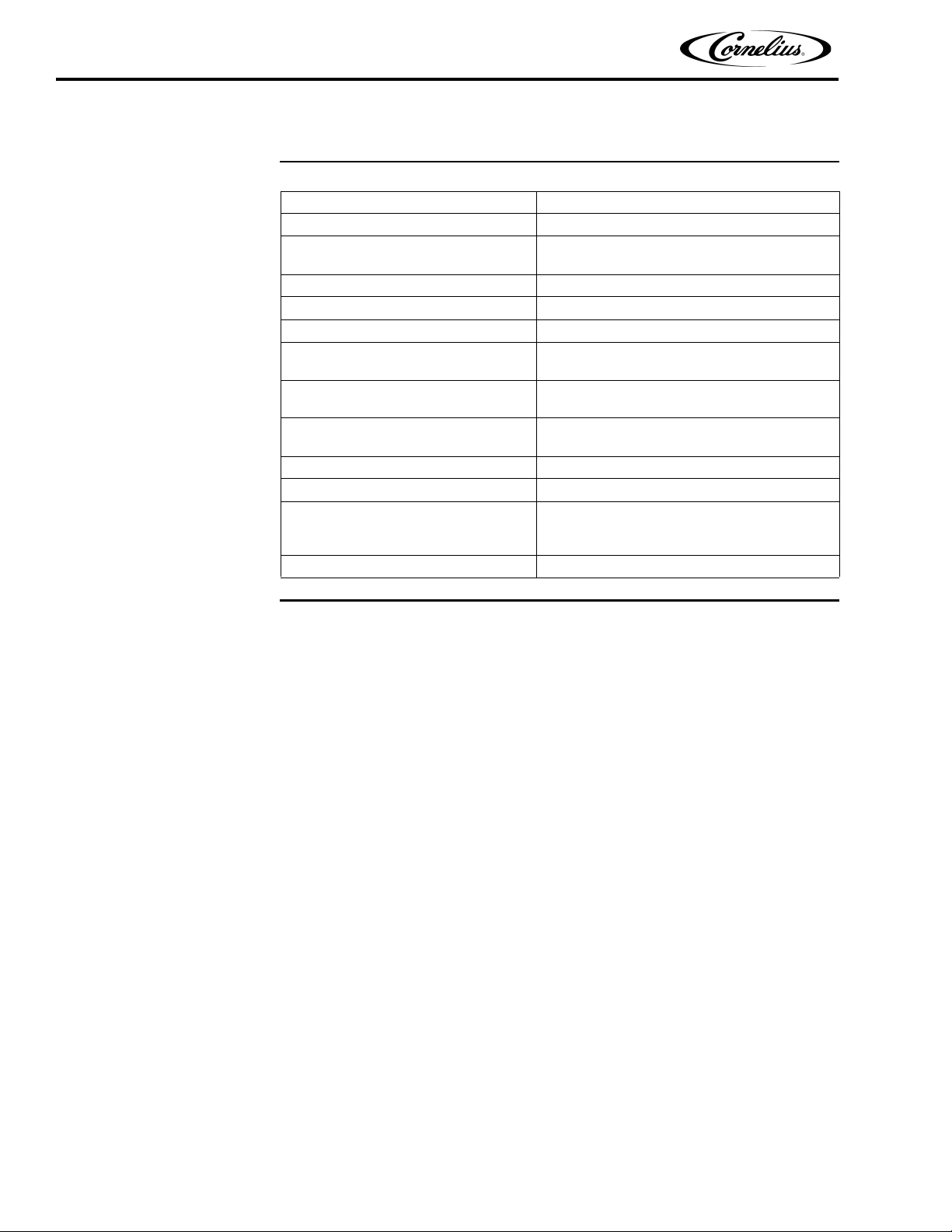
Specifications ............................................................................................................................6
Installation ......................................................................................................................................7
Delivery Inspection and Unpacking .........................................................................................7
Installation Kit ..........................................................................................................................7
Location ....................................................................................................................................7
Supply Connections ..................................................................................................................8
Electrical Requirements ......................................................................................................8
Line Voltage .................................................................................................................8
Power ............................................................................................................................9
Nitrogen Requirements .......................................................................................................9
Nitrogen Connections ...................................................................................................9
Initial Nitrogen Pressure Setup ...................................................................................10
Water Requirements .........................................................................................................10
Ventilation Requirements .......................................................................................................11
Freestanding Unit Installation .................................................................................................11
Under Counter Unit Installation .............................................................................................17
commissioning the Unit ................................................................................................................24
Initial Startup ..........................................................................................................................24
Connecting Power .............................................................................................................24
Unit Details .............................................................................................................................24
Cleaning Products .............................................................................................................24

Unit Cleaning and Sanitation ............................................................................................25
Changing Coffee Types ..........................................................................................................30
Unit Foam Head Height Adjustment ................................................................................31
System Diagrams ..........................................................................................................................33
Electrical Diagram ..................................................................................................................33
Nitrogen Flow Diagram ..........................................................................................................34

Cold Nitro Brew BIB Dispenser Installation Manual
© 2017, Cornelius Inc. All Rights Reserved ‐1 ‐Publication Number: 621058723INS
SAFETY INSTRUCTIONS
READ AND FOLLOW ALL SAFETY INSTRUCTIONS
Safety Overview
•Read and follow ALL SAFETY INSTRUCTIONS in this manual and any warning/
caution labels on the unit (decals, labels or laminated cards).
•Read and understand ALL applicable OSHA (Occupational Safety and Health
Administration) safety regulations and/or national and local codes before
operating this unit.
Recognition
DIFFERENT TYPES OF ALERTS
!DANGER:
Indicates an immediate hazardous situation which, if not avoided, WILL result in
serious injury, death or equipment damage.
!DANGER:
Indicates a potentially hazardous situation which, if not avoided, COULD result in
serious injury, death, or equipment damage.
CAUTION:
!
Indicates a potentially hazardous situation which, if not avoided, MAY result in
minor or moderate injury or equipment damage.
SAFETY TIPS
•Carefully read and follow all safety messages in this manual and safety signs on
the unit.
•Keep safety signs in good condition and replace missing or damaged items.
•Learn how to operate the unit and how to use the controls properly.
Recognize Safety Alerts
This is the safety alert symbol. When you see it in this manual or on the unit, be alert to
the potential of personal injury or damage to the unit.
!

Cold Nitro Brew BIB Dispenser Installation Manual
Publication Number: 621058723INS ‐2 ‐© 2017, Cornelius Inc. All Rights Reserved
•Donotlet anyone operate the unit without proper training. This appliance is not
intended for use by very young children or infirm persons without supervision.
Young children should be supervised to ensure that they do not play with the
appliance.
•Keep your unit in proper working condition and do not allow unauthorized
modifications to the unit.
QUALIFIED SERVICE PERSONNEL
!WARNING:
Only trained and certified electrical, plumbing and refrigeration technicians should service
this unit. ALL WIRING AND PLUMBING MUST CONFORM TO NATIONAL AND LOCAL
CODES. FAILURE TO COMPLY COULD RESULT IN SERIOUS INJURY, DEATH OR EQUIPMENT
DAMAGE.
SAFETY PRECAUTIONS
This unit has been specifically designed to provide protection against personal injury. To
ensure continued protection, observe the following:
!WARNING:
Disconnect Power When Servicing ‐Disconnect power to the unit before servicing follow‐
ing all lock out/tag out procedures established by the user. Verify all of the power is off to
the unit before any work is performed. Failure to disconnect the power could result in seri‐
ous injury, death or equipment damage.
!WARNING:
Avoid Clutter - Always be sure to keep area around the unit clean and free of clutter. Failure
to keep this area clean may result in injury or equipment damage.
!WARNING:
Provide Emergency Power Off (EPO) ‐Connect to a switchable AC outlet (switch within
operator’s reach) or ensure that the AC receptacle is in a readily‐accessible location allow‐
ing quick, emergency shutdown by the operator.
SHIPPING AND STORAGE
!WARNING:
Sanitize and Drain Unit‐Before shipping, storing, or relocating the unit sanitize it and drain
all sanitizing solution from the system. A freezing ambient environment will cause residual
solution, or water remaining inside the unit, to freeze, resulting in damage to internal com‐
ponents.

Cold Nitro Brew BIB Dispenser Installation Manual
© 2017, Cornelius Inc. All Rights Reserved ‐3 ‐Publication Number: 621058723INS
UNIT LOCATION
CAUTION:
!
The CNB BiB unit is not suitable for installation in an area where a water jet could
be used.
CAUTION:
!
The CNB BiB unit must be located in a horizontal position.
CAUTION:
!
This CNB BiB unit is not designed for use in outdoor locations.
POWER CORD
CAUTION:
!
If the power cord is damaged, it must be replaced by a special cord available from
the manufacturer or its service agent.
SOUND LEVELS
CAUTION:
!
The A‐weighted sound pressure level has been determined to be below 60 dBA.
MACHINE USAGE
CAUTION:
!
This unit is not intended for use by persons (including children) with reduced
physical, sensory or mental capabilities or lack of experience and knowledge,
unless they have been given supervision or instruction concerning use of the unit
by a person responsible for their safety.
CAUTION:
!
Children should not be allowed to play with or operate the unit.
CAUTION:
!
This appliance is intended to be used in commercial applications for the
dispensing of only non‐hazardous product.

Cold Nitro Brew BIB Dispenser Installation Manual
Publication Number: 621058723INS ‐4 ‐© 2017, Cornelius Inc. All Rights Reserved
UNIT CLEANING
CAUTION:
!
This unit MUST NOT be cleaned by using a water jet.
GROUNDING INSTRUCTIONS
CAUTION:
!
This appliance must be grounded. In the event of malfunction or breakdown,
grounding provides a path of least resistance for electric current to reduce the risk
of electric shock. This appliance is equipped with a cord having an equipment‐
grounding conductor and a grounding plug. The plug must be plugged into an
appropriate outlet that is properly installed and grounded in accordance with all
local codes and ordinances.
!DANGER:
Improper connection of the equipment‐grounding conductor can result in a risk of
electrical shock. The conductor with green insulation with or without yellow
stripes is the equipment grounding conductor. If repair or replacement of the cord
or plug is necessary, do not connect the equipment grounding conductor to a live
terminal. If in doubt whether the appliance is properly grounded, check with a
qualified electrician or serviceman. Do not modify the plug provided with the
appliance ‐if it will not fit the outlet, have a proper outlet installed by a qualified
electrician.
CAUTION:
!
This appliance is for use on electrical circuits, and has a grounding plug that looks
like the plug illustrated in Figure 1.
A qualified electrician should be consulted if there is any doubt about the outlet
box being properly grounded.
Figure 1.
3‐Prong Plug *
* Example of grounded North American plug.

Cold Nitro Brew BIB Dispenser Installation Manual
© 2017, Cornelius Inc. ‐5 ‐Publication Number: 621058723INS
SYSTEM OVERVIEW
OVERVIEW
The Cold Nitro Brew (CNB BiB) Dispenser is a self‐contained, on‐demand, in‐line nitrogen infu‐
sion unit. The CNB BiB (Bag‐in‐Box) unit allows for still and nitro product to be poured from the
same post‐mixed source through different dispensers.
The CNB BiB unit provides the highest quality drink appearance and consistency, while keeping
operation and maintenance simple and straightforward.
FEATURES
• Durable, robust design
• Easy to use – double‐dispenser lever interface
• Easy to Clean – dispense area is easily wiped down
• Small Footprint – CNB BiB design allows the unit to be installed remotely and under‐
counter with minimum space requirement.
• OPTIMIZED DESIGN — Efficient front breathing design allows the unit to be installed
under a counter top or stand‐alone.
• SELF‐CONTAINED DESIGN — Water, Nitrogen, and electrical connections are all that
are needed, a drain is optional. The unit automatically chills water for cold bever‐
ages.
• PROPRIETARY INFUSION — Unique infusion process layers the beverage with an
industry leading, long lasting cascade.
• No Mixing, No Shaking, No Filling. Just connect the BIB and go!
• Utilizes concentrated BIBs of cold brew, 1:3 ‐1:5 ratio automatic mixing.
• Units are factory set to a 1:5 ratio.

Cold Nitro Brew BIB Dispenser Installation Manual
Publication Number: 621058723INS ‐6 ‐© 2016, Cornelius Inc.
SPECIFICATIONS
Table 1.
Food Grade Nitrogen Requirements 80 psi (0.55 MPa) at input
Nitrogen Input Connection 90˚¼” BARB
Water Supply Requirements Filtered water @ > 0.5 GPM and 90 psi
(0.62 MPa) at store
Water Supply Connection 90˚3/8” BARB
Electrical Ratings 120V/60Hz/4.5Amps
Drain Line 3/8” ID Tubing
Cabinet Capacity (2) 3‐gallon BiBs (Approx. box Dimensions:
13 1/2” H x 7 1/2” W x 9 1/2” D)
Cabinet (Door closed, not including tower) 30.1" (76.5 cm) D (includes standoffs) x 20” (50.8
cm) W x 34” (86.4 cm) H
Cabinet (Door closed, including tower) 30.1" (76.5 cm) D (includes standoffs) x 20” (50.8
cm) W x 50.8” (129 cm) H
Shipping Weight 285 lbs. (129.3 kg)
Cup Clearance 7 1/4” (18.4 cm) drip tray to spout nozzle
Recommended pouring size:
At 75°F ambient temperature and 75°F input water
temperature, the unit can pour drinks at 16 oz. per
minute with a drink temperature of 41°F or lower.
Ambient Operating Temperature 55° F to 100° F (12.8° C to 37.8° C)

Cold Nitro Brew BIB Dispenser Installation Manual
© 2017, Cornelius Inc. ‐7 ‐Publication Number: 621058723INS

Cold Nitro Brew BIB Dispenser Installation Manual
Publication Number: 621058723INS ‐7 ‐© 2017, Cornelius Inc.
INSTALLATION
!WARNING:
Only trained and certified electrical, plumbing and refrigeration technicians should
service this unit.
ALL WIRING AND PLUMBING MUST CONFORM TO NATIONAL AND LOCAL CODES. FAIL-
URE TO COMPLY COULD RESULT IN SERIOUS INJURY, DEATH OR EQUIPMENT DAMAGE.
DELIVERY INSPECTION AND UNPACKING
NOTE: Cornelius is not responsible for damaged freight. If damage is found, you
must save all packaging material and contact the freight carrier. Failure to
contact the carrier within 48 hours of receipt may void your claim.
1. Inspect the carton and note any damage, even if it appears minor. If the carton is
damaged, note on the consignee copy of the freight invoice “exterior carton
damage‐concealed damage possible” and contact the freight company immedi‐
ately.
2. Remove the strapping from the box, remove the tape and lift the carton off the
pallet.
3. Remove the internal packing materials and installation kit boxes from the unit.
Carefully inspect the unit for damage.
4. Inspect the device to make sure it has no scratches, dents or any other cosmetic
defects.
5. Open the packages of loose parts and inspect all of the parts for damage or miss‐
ing parts. Check the parts against the packing list to ensure receipt of all parts.
INSTALLATION KIT
Included in the shipping carton is an accessories kit that is used to connect the elements of
the beverage system together. Verify the contents of the installation kit with the pictorial
sheet enclosed in the kit. For a detailed installation procedure, refer to Table 2 on page 11.
LOCATION
Select a location in a convenient area, close to a grounded electrical AC outlet that either includes
a power switch or is located such that the operator may easily disconnect the power cord.

Cold Nitro Brew BIB Dispenser Installation Manual
© 2017, Cornelius Inc. ‐8 ‐Publication Number: 621058723INS
SUPPLY CONNECTIONS
!WARNING:
Only trained and certified electrical, plumbing and refrigeration technicians should
service this unit.
ALL WIRING AND PLUMBING MUST CONFORM TO NATIONAL AND LOCAL CODES. FAIL-
URE TO COMPLY COULD RESULT IN SERIOUS INJURY, DEATH OR EQUIPMENT DAMAGE.
All of the electrical and supply connections to the CNB BIB unit are located on the back of the
unit, as shown in Figure 2. The unit is filled manually from the front.
Figure 2.
Electrical
Requirements
!WARNING:
Refer to the nameplate to determine the power requirements before connecting
electrical power to the CNB BIB unit. AC Power cords should comply with safety
requirements outlined in the EC Standards (EN 60335‐1 1 Clause 24.1) in countries
where CE compliance is required. All cords must be HD 21 or HD 22.
Line Voltage
The intended line voltage for the unit are 120 VAC +10%/‐15%, 60 Hz. Measure the voltage at
the wall outlet to verify proper wiring of the outlet before plugging the unit in.
AC Power
Cord
Socket
Drip‐tray
Water
Inlet Port
Nitrogen
Drain
Inlet Port
3/8” BARB
3/8” BARB
1/4” BARB

Cold Nitro Brew BIB Dispenser Installation Manual
Publication Number: 621058723INS ‐9 ‐© 2017, Cornelius Inc.
Power
The power supply must have overload protection such as a circuit breaker or fuse that
meets local and national electrical codes.
All units are connected to AC power by plugging the electrical plug into the proper wall outlet.
Nitrogen
Requirements
!WARNING:
Failure to install the wall bracket may result in a tipping hazard.
FAILURE TO COMPLY COULD RESULT IN SERIOUS INJURY, DEATH OR EQUIPMENT
DAMAGE.
NOTE: Nitrogen connections require 1/4” I.D. tubing. All hoses must reach the
back of the unit including an adequate amount of extra tubing to allow
the unit to be pulled out for servicing.
Use a dedicated secondary regulator adjusted to 80 psi (0.55 MPa) to supply
the unit.
Nitrogen Connections
!WARNING:
Only trained and certified electrical, plumbing and refrigeration technicians should
service this unit.
ALL WIRING AND PLUMBING MUST CONFORM TO NATIONAL AND LOCAL CODES. FAIL-
URE TO COMPLY COULD RESULT IN SERIOUS INJURY, DEATH OR EQUIPMENT DAMAGE.
The store regulator should be set for 80 psi (0.55 MPa) at the unit. Run the tubing for the
nitrogen from the regulator to the unit and make all appropriate connections. Do not turn
on the nitrogen supply to the unit.
The nitrogen connections are located on the back of the CNB BIB unit. Figure 2 shows the
nitrogen connections to the unit.
CAUTION:
!
Only Food‐Grade Nitrogen gas can be used with the CNB BIB unit, no other gases
can be used.
!DANGER:
CO2must not be used in this unit, it can create a poisonous formation that can
lead to serious injuries or death.

Cold Nitro Brew BIB Dispenser Installation Manual
© 2017, Cornelius Inc. ‐10 ‐Publication Number: 621058723INS
Initial Nitrogen
Pressure Setup
During the installation of the nitrogen tanks, technicians will connect and adjust the valves,
shown in Figure 3. Primary regulator is to be supplied by the installer.
NOTE: The units are calibrated before delivery and are adjusted at the site by the
installation technician.
Figure 3.
Water Requirements
!WARNING:
It is the responsibility of the installer to ensure that the water supply to the
booster pump preceding the dispensing equipment is provided with back flow
protection by an air gap as defined in ANSI A 112.1.2‐1979; or an approved
vacuum breaker or other such method as proved effective by test and must
comply with all federal, state and local codes.
In stores with water pressure below 70 PSI a booster pump will be required. Use appropri‐
ate materials to connect the water supply to the booster pump. The water input connection
from the booster pump is located on the back of the dispenser unit, as shown in Figure 2.
Store Water
Inlet
Pressurized
Water Outlet
to Dispenser
Water Booster Pump
Accumulator
Bladder
Pressure
Port
Figure 4
Primary
Tank
Regulator
Pressure
Secondary
Tank
Gauge
Regulator
Pressure
Gauge

Cold Nitro Brew BIB Dispenser Installation Manual
Publication Number: 621058723INS ‐11 ‐© 2017, Cornelius Inc.
VENTILATION
REQUIREMENTS
MINIMUM AIRFLOW CLEARANCE
IMPORTANT: The unit is front‐breathing and requires no minimum side or back clearance.
Thus it is critical to prevent any blockage of the lower front of the unit.
Air circulates through the bottom section of the cabinet to help cool the ice bank agitator
motor and the refrigeration condenser. Failure to maintain front clearance space will
reduce the capacity of the unit and cause premature compressor failure.
FREESTANDING
UNIT INSTALLATION
!WARNING:
Only trained and certified electrical, plumbing and refrigeration technicians should
service this unit.
NOTE: Read the entire manual before installing the CNB BIB unit, perform the
procedure in Table 2 to install the CNB BIB unit.
Table 2
Step Action
1
Remove the staples holding the box to the skid. Unpack the
CNB BIB unit, remove the installation kit boxes from the unit
and inspect the unit and installation kit.
2
Select the installation location for the CNB BIB unit. Choose a
location in a well ventilated area, close to a grounded electri‐
cal outlet. If possible do not place the unit
close to hot and/or steaming machines. If using a nitrogen
generator, skip step 3 & 4, connect and startup generator per
instructions.

Cold Nitro Brew BIB Dispenser Installation Manual
© 2017, Cornelius Inc. ‐12 ‐Publication Number: 621058723INS
3
Select the location for the nitrogen tank(s):
A. Install the primary regulator onto the nitrogen tank.
Tighten the regulator to the tank using a wrench.
B. Connect the 1/4” ID Tygon tubing to the primary
regulator output.
4 Secure the nitrogen tank(s) with a suitable wall bracket.
5
Route the 1/4” ID Tygon tubing from the nitrogen tank to the
CNB BIB unit and connect the tubing to the Nitrogen inlet
using a hose clamp.
6
Install the tap units to the dispensing tower couplings. The
taps and couplings include radial teeth that mate with one
another to lock the tap in position. Be sure to align the tap to
true vertical before hand tightening the threaded coupling
ring. Fully secure the coupling ring using the wrench pro‐
vided.
Be careful not to over tighten. Only slight pressure is
needed on the wrench.
Table 2
Step Action
Nitrogen
Inlet Port
Water
Inlet Port

Cold Nitro Brew BIB Dispenser Installation Manual
Publication Number: 621058723INS ‐13 ‐© 2017, Cornelius Inc.
7
(Optional) If required, install the water booster pump either
onto the back of the CNB BIB cabinet (if clearance space is
available) or onto the wall by securing its base bracket with
appropriate mounting hardware. Two holes are supplied on
the back of the unit for mounting the booster pump assem‐
bly. Place booster pump less than 10 feet away from the unit.
WARNING: Due to a potential hot surface of the pump motor
casing, the booster‐pump assembly must be installed in a loca‐
tion where it is not accessible by users.
Water Booster Pump
Booster Pump Mounted
8
Connect the source water line to the cabinet Water inlet (or
to the optional booster pump inlet).
A. Connect the 3/8” ID tubing to the water source fitting.
B. Route the tubing from the water source to the CNB BIB
Water inlet as shown in figure 1 (or to the water booster
pump inlet, shown at right).
C. Connect the tubing using a hose clamp.
9
(Optional) If the water booster pump is required connect the
water line to booster pump outlet.
A. Connect the 3/8” ID tubing to the water booster pump
outlet using a hose clamp
10
Connect water line to dispenser Water inlet.
A. Route the tubing to back of the CNB BIB cabinet.
B. Install it on the cabinet water inlet using a hose clamp.
11
Connect the drip‐tray drain line and elbow.
A. Route the 3/8” ID tubing to the selected drain location.
ensure there are no restrictions or kinks in the tubing.
B. The drain tubing assembly is factory installed. The gray
elbow can be removed by twisting and pulling. It is
assembled by friction and NOT glued in place.
C. Ensure the strain relief is mounted to the rear of the
machine.
Table 2
Step Action
Water Nitrogen
Inlet
Port
Inlet
Port

Cold Nitro Brew BIB Dispenser Installation Manual
© 2017, Cornelius Inc. ‐14 ‐Publication Number: 621058723INS
12
Access the ice bank for water filling.
A. Lift grill upwards and pull bottom towards the front to
disengage the locking tabs in the bottom frame assem‐
bly
B. Unfasten cover (remove 2 screws at top of cover).
C. Slide filter to the left
13
Open the ice‐bank water‐refill cover.
A. Remove the thumbscrew securing the ice‐bank refill cover.
B. Lift off the cover and set it aside.
Table 2
Step Action
Two Screws
Cover Thumbscrew

Cold Nitro Brew BIB Dispenser Installation Manual
Publication Number: 621058723INS ‐15 ‐© 2017, Cornelius Inc.
14
Fill the ice bank with potable water.
A. Use a funnel and pour water into refill opening. Capacity
is approximately 3.6 gallons (13.6 liters). The reservoir is
full when water begins trickling through the clear over-
flow tubing at the lower-front, center of the ice bank.
NOTE: The ice bank may also be filled with chilled water
to reduce the time for cool down to 33°F (0°C). (Typical
cooling time using room‐temperature water is 6 hours.)
NOTE: The ice bank typically requires a water refill every
month. Observe the water level shown in the fill tube
(with red cap). Remove cap for accurate reading.
15
Replace the air filter / grille
A. Replace air filter bracket and mount with the 2 screws
removed above
B. Replace air filter by sliding to the right
C. Insert grille assembly into the top at an angle first
D. Push bottom of grille in place and let grille lower into
place
E. Ensure the tabs in the bottom of the grille are locked
into the slots in the frame assembly
16 Remove the protective film from the drip‐tray grate. Place it
into the drip tray.
Table 2
Step Action
Overflow
Connection
Pour
water into
opening
Other manuals for CNB BIB
1
Table of contents
Other Cornelius Brewing System manuals
Popular Brewing System manuals by other brands

BREWHA Equipment Co Ltd.
BREWHA Equipment Co Ltd. BIAC user manual

Newco
Newco LCD-TCH Operating instructions manual

KeyKeg
KeyKeg 10 L General instructions

Breville
Breville the BrevillePrecision Brewer Thermal Instruction book

BIELMEIER
BIELMEIER BHG 407 instruction manual

KegLand
KegLand BrewZilla 35L Gen 4 instruction manual

MICROMATIC
MICROMATIC GROWLER FILLER Installation, use & maintenance guide

Curtis
Curtis SERA2B user guide

KegLand
KegLand KL14649 instruction manual

Wilbur Curtis Company
Wilbur Curtis Company D1000GT Service manual

BRAVILOR BONAMAT
BRAVILOR BONAMAT Aurora GTBSH-001 user manual

Bunn
Bunn ICB Installation & operating guide