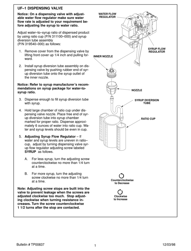
Cornelius Post-Mix Valves UFB-1 Manual

Installation and service manual
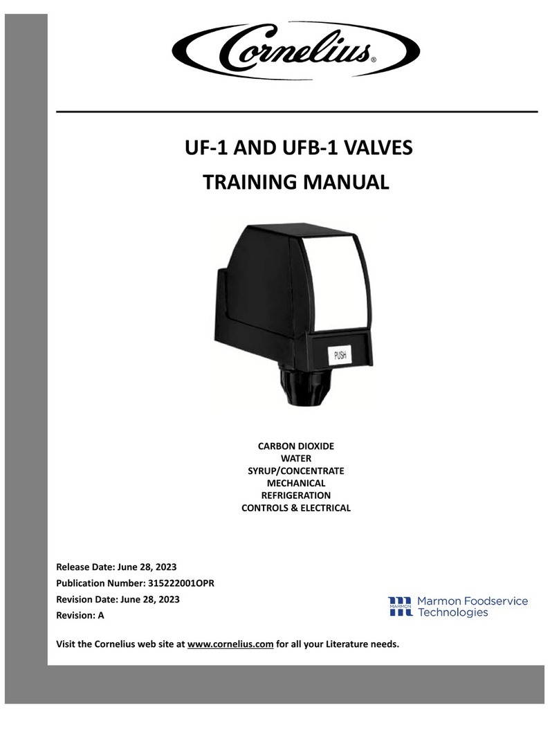
Dispensing valve
UFB1
PUSH

Legal notice
Installation and service manual (Original)
Document no. TD2004100
Dispensing valve
UFB1 portion control: Part number: 741000401 (3 oz)
UFB1 push button: Part number: 741000399 (3 oz) | 740001214 (4 oz)
UFB1 dispensing lever: Part number: 741000403 (3 oz) | 740001213 (4 oz)
UFB1 OptiFill: Part number: 741000405 (3 oz)
UFB1
Version
Date of issue: 15/03/2019
Revision status: Index 0
www.cornelius-emea.com Cornelius Deutschland GmbH
Carl-Leverkus-Str. 15
40764 Langenfeld
Germany
Tel.: +49 (0) 21 73 / 79 3 – 0
Fax: +49 (0) 21 73 / 77 4 – 38
E-Mail: info@cornelius.com
Protection notices (in accordance with DIN ISO 16016:2017-08)
The reproduction, distribution and utilisation of this document as well as the communication of its contents is prohibited, unless
expressly permitted. Violations shall result in an obligation to pay damages. All rights reserved with regard to filing for/registering
patents, utility models or design patents.

Cornelius Deutschland GmbH
Document no. TD2004100
Version 15/03/2019, Index 0
Installation and service manual Dispensing valve
UFB1
1
Installation and service manual
Dispensing valve
Table of contents
1 Safety . . . . . . . . . . . . . . . . . . . . . . . . . . . . . . . . . . . . . . . . . . . . . . . . . . . . . . . . . . . . . . . . . . . . . . . . 3
1.1 Intended use . . . . . . . . . . . . . . . . . . . . . . . . . . . . . . . . . . . . . . . . . . . . . . . . . . . . . . . . . . . . . . . . . . . . 3
1.2 Improper use. . . . . . . . . . . . . . . . . . . . . . . . . . . . . . . . . . . . . . . . . . . . . . . . . . . . . . . . . . . . . . . . . . . . 3
1.3 Staff. . . . . . . . . . . . . . . . . . . . . . . . . . . . . . . . . . . . . . . . . . . . . . . . . . . . . . . . . . . . . . . . . . . . . . . . . . 3
1.4 Presentation of warnings . . . . . . . . . . . . . . . . . . . . . . . . . . . . . . . . . . . . . . . . . . . . . . . . . . . . . . . . . . . . 3
1.5 Safety information . . . . . . . . . . . . . . . . . . . . . . . . . . . . . . . . . . . . . . . . . . . . . . . . . . . . . . . . . . . . . . . . 3
1.5.1 Safety information to prevent personal injury and equipment damage . . . . . . . . . . . . . . . . . . . . . . . . . . . . . . 3
1.5.2 Safety information for using electrical assemblies . . . . . . . . . . . . . . . . . . . . . . . . . . . . . . . . . . . . . . . . . . . 3
2 Transport and packaging . . . . . . . . . . . . . . . . . . . . . . . . . . . . . . . . . . . . . . . . . . . . . . . . . . . . . . . . . . 4
2.1 Storage . . . . . . . . . . . . . . . . . . . . . . . . . . . . . . . . . . . . . . . . . . . . . . . . . . . . . . . . . . . . . . . . . . . . . . . 4
2.2 Disposal . . . . . . . . . . . . . . . . . . . . . . . . . . . . . . . . . . . . . . . . . . . . . . . . . . . . . . . . . . . . . . . . . . . . . . . 4
3 Description . . . . . . . . . . . . . . . . . . . . . . . . . . . . . . . . . . . . . . . . . . . . . . . . . . . . . . . . . . . . . . . . . . . . 5
3.1 Assemblies and components . . . . . . . . . . . . . . . . . . . . . . . . . . . . . . . . . . . . . . . . . . . . . . . . . . . . . . . . . 5
3.1.1 Dispensing valve UFB1 portion control. . . . . . . . . . . . . . . . . . . . . . . . . . . . . . . . . . . . . . . . . . . . . . . . . . . 5
3.1.2 Dispensing valve UFB1 push button . . . . . . . . . . . . . . . . . . . . . . . . . . . . . . . . . . . . . . . . . . . . . . . . . . . . 6
3.1.3 Dispensing valve UFB1 dispensing lever . . . . . . . . . . . . . . . . . . . . . . . . . . . . . . . . . . . . . . . . . . . . . . . . . 7
3.1.4 Dispensing valve UFB1 OptiFill. . . . . . . . . . . . . . . . . . . . . . . . . . . . . . . . . . . . . . . . . . . . . . . . . . . . . . . . 8
3.1.5 Standard dispensing nozzle . . . . . . . . . . . . . . . . . . . . . . . . . . . . . . . . . . . . . . . . . . . . . . . . . . . . . . . . . . 8
3.1.6 Juice dispensing nozzle . . . . . . . . . . . . . . . . . . . . . . . . . . . . . . . . . . . . . . . . . . . . . . . . . . . . . . . . . . . . 9
3.2 Functions within the dispensing system . . . . . . . . . . . . . . . . . . . . . . . . . . . . . . . . . . . . . . . . . . . . . . . . . . 9
3.3 How the dispensing valve works . . . . . . . . . . . . . . . . . . . . . . . . . . . . . . . . . . . . . . . . . . . . . . . . . . . . . . . 9
3.4 Technical data . . . . . . . . . . . . . . . . . . . . . . . . . . . . . . . . . . . . . . . . . . . . . . . . . . . . . . . . . . . . . . . . . . . 9
4 Installation/removal . . . . . . . . . . . . . . . . . . . . . . . . . . . . . . . . . . . . . . . . . . . . . . . . . . . . . . . . . . . . . . 10
4.1 Installing the dispensing valve . . . . . . . . . . . . . . . . . . . . . . . . . . . . . . . . . . . . . . . . . . . . . . . . . . . . . . . . 10
4.2 Removing the dispensing valve . . . . . . . . . . . . . . . . . . . . . . . . . . . . . . . . . . . . . . . . . . . . . . . . . . . . . . . 11
4.3 Installing the soda lever. . . . . . . . . . . . . . . . . . . . . . . . . . . . . . . . . . . . . . . . . . . . . . . . . . . . . . . . . . . . . 11
4.4 Removing the soda lever . . . . . . . . . . . . . . . . . . . . . . . . . . . . . . . . . . . . . . . . . . . . . . . . . . . . . . . . . . . . 12
5 Maintenance . . . . . . . . . . . . . . . . . . . . . . . . . . . . . . . . . . . . . . . . . . . . . . . . . . . . . . . . . . . . . . . . . . . 12
5.1 Maintenance table . . . . . . . . . . . . . . . . . . . . . . . . . . . . . . . . . . . . . . . . . . . . . . . . . . . . . . . . . . . . . . . . 12
5.2 Carrying out a visual inspection of the seals on the diffusor and baffle . . . . . . . . . . . . . . . . . . . . . . . . . . . . . . 13
5.3 Cleaning the valves . . . . . . . . . . . . . . . . . . . . . . . . . . . . . . . . . . . . . . . . . . . . . . . . . . . . . . . . . . . . . . . 14
6Repairs
. . . . . . . . . . . . . . . . . . . . . . . . . . . . . . . . . . . . . . . . . . . . . . . . . . . . . . . . . . . . . . . . . . . . . . . 15
6.1 Replacing the front valve cover. . . . . . . . . . . . . . . . . . . . . . . . . . . . . . . . . . . . . . . . . . . . . . . . . . . . . . . . 15
6.2 Replacing the rear valve cover . . . . . . . . . . . . . . . . . . . . . . . . . . . . . . . . . . . . . . . . . . . . . . . . . . . . . . . . 16
6.3 Replacing the control panel . . . . . . . . . . . . . . . . . . . . . . . . . . . . . . . . . . . . . . . . . . . . . . . . . . . . . . . . . . 16
6.4 Replacing the OptiFill module. . . . . . . . . . . . . . . . . . . . . . . . . . . . . . . . . . . . . . . . . . . . . . . . . . . . . . . . . 17
6.5 Replacing the flow controller . . . . . . . . . . . . . . . . . . . . . . . . . . . . . . . . . . . . . . . . . . . . . . . . . . . . . . . . . 18
6.6 Replacing the block mount. . . . . . . . . . . . . . . . . . . . . . . . . . . . . . . . . . . . . . . . . . . . . . . . . . . . . . . . . . . 19
6.7 Replacing the microswitch . . . . . . . . . . . . . . . . . . . . . . . . . . . . . . . . . . . . . . . . . . . . . . . . . . . . . . . . . . . 19
6.8 Replacing the pull-type solenoid . . . . . . . . . . . . . . . . . . . . . . . . . . . . . . . . . . . . . . . . . . . . . . . . . . . . . . . 20
6.9 Replacing the dispensing lever . . . . . . . . . . . . . . . . . . . . . . . . . . . . . . . . . . . . . . . . . . . . . . . . . . . . . . . . 21
6.10 Replacing the soda lever . . . . . . . . . . . . . . . . . . . . . . . . . . . . . . . . . . . . . . . . . . . . . . . . . . . . . . . . . . . . 21
6.11 Replacing the dispensing nozzle . . . . . . . . . . . . . . . . . . . . . . . . . . . . . . . . . . . . . . . . . . . . . . . . . . . . . . . 22
7 Configuring and adjusting. . . . . . . . . . . . . . . . . . . . . . . . . . . . . . . . . . . . . . . . . . . . . . . . . . . . . . . . . . 24
7.1 Configuring portion control . . . . . . . . . . . . . . . . . . . . . . . . . . . . . . . . . . . . . . . . . . . . . . . . . . . . . . . . . . . 24
7.1.1 “Standard” configuration mode . . . . . . . . . . . . . . . . . . . . . . . . . . . . . . . . . . . . . . . . . . . . . . . . . . . . . . . . 25
7.1.2 “Top-up times” configuration mode . . . . . . . . . . . . . . . . . . . . . . . . . . . . . . . . . . . . . . . . . . . . . . . . . . . . . 25
7.1.3 “Incremental” configuration mode . . . . . . . . . . . . . . . . . . . . . . . . . . . . . . . . . . . . . . . . . . . . . . . . . . . . . . 26
7.1.4 Restoring the factory settings . . . . . . . . . . . . . . . . . . . . . . . . . . . . . . . . . . . . . . . . . . . . . . . . . . . . . . . . . 26
7.1.5 Procedure for non-reactive modules . . . . . . . . . . . . . . . . . . . . . . . . . . . . . . . . . . . . . . . . . . . . . . . . . . . . 27
Cornelius Deutschland GmbH
Document no. TD2004100
Version 15/03/2019, Index 0
Installation and service manual Dispensing valve
UFB1
2
7.2 Configuration of the OptiFill module . . . . . . . . . . . . . . . . . . . . . . . . . . . . . . . . . . . . . . . . . . . . . . . . . . . . . 27
7.2.1 Configuring the fill times . . . . . . . . . . . . . . . . . . . . . . . . . . . . . . . . . . . . . . . . . . . . . . . . . . . . . . . . . . . . 27
7.2.2 Configuring the top-up delay. . . . . . . . . . . . . . . . . . . . . . . . . . . . . . . . . . . . . . . . . . . . . . . . . . . . . . . . . . 28
7.2.3 Checking and setting the timed dispensing function . . . . . . . . . . . . . . . . . . . . . . . . . . . . . . . . . . . . . . . . . . 28
7.3 Adjusting the valves . . . . . . . . . . . . . . . . . . . . . . . . . . . . . . . . . . . . . . . . . . . . . . . . . . . . . . . . . . . . . . . 28
8 Errors and malfunctions . . . . . . . . . . . . . . . . . . . . . . . . . . . . . . . . . . . . . . . . . . . . . . . . . . . . . . . . . . . 29
8.1 Troubleshooting table . . . . . . . . . . . . . . . . . . . . . . . . . . . . . . . . . . . . . . . . . . . . . . . . . . . . . . . . . . . . . . 29

Safety
Cornelius Deutschland GmbH
Document no. TD2004100
Version 15/03/2019, Index 0
Installation and service manual Dispensing valve
UFB1
3
1Safety
1.1 Intended use
By using the unit as intended you will not only protect yourself, but also prevent damage occurring to the dispensing valve and its
components!
You can find further information about the intended use of the unit in the dispensing valve operator manual, document no.
TD2004000.
1.2 Improper use
Improper use of the dispensing valve, and unauthorised modifications to the dispensing valve and its components may cause per-
sonal injury and equipment damage for which Cornelius Deutschland GmbH shall assume no liability. Improper use of the dispens-
ing valve is prohibited.
You can find further information about the improper use of the unit – and the meaning of improper use – in the dispensing valve
operator manual, document no. TD2004000.
1.3 Staff
There is a clear definition as to what group of people is permitted to carry out what type of work on the dispensing valve. You can
find further information about who is authorised to carry out what type of work on the dispensing valve in the dispensing valve
operator manual, document no. TD2004000.
1.4 Presentation of warnings
The documents supplied with the dispensing valve provide warnings regarding any dangers or hazards that might exist. You can
find more information about the design and presentation of warnings in the dispensing valve operator manual, document no.
TD2004000.
1.5 Safety information
1.5.1 Safety information to prevent personal injury and equipment damage
Any work on the dispensing valve and its components which goes beyond operation and beyond the servicing and maintenance
tasks that the operator is authorised for, may only be performed by experts (for a definition of experts, see the dispensing valve
operator manual, document no. TD2004000). Furthermore, it is crucial that when performing work on the dispensing valve all safe-
ty information is observed; this information is set out in the following sections. Some of the tasks may have additional safety infor-
mation which highlights the specific dangers or hazards associated with such work.
WARNING!
Risk of burns when touching hot parts of the unit!
Touching parts of the unit after it has been in continuous use over an extended period of time will result in a risk
of burns.
• Take appropriate safeguard measures, such as by wearing heat-resistant protective gloves.
1.5.2 Safety information for using electrical assemblies
DANGER!
To prevent risks to health and safety, please always observe the following five safety rules:
These five safety rules are to be applied before carrying out work on the electrical system and in the order stated
below. Once work is completed, the safety rules are to be undone again in reverse order.
• 1. Disconnect from power.
• 2. Secure against reconnection.
• 3. Check that the system is disconnected from power.
• 4. Ground and short-circuit the system.
• 5. Cover or separate adjacent live parts.
NOTICE!
• Make sure that the cable markers are not removed from the cables and/or mark or label the cables such
that they can be correctly assigned during installation.
ATTENTION!
Cables must be fixed in place using cable ties.
When fixing cables in place using cable ties, observe the following points:
• Once work on the unit is completed, return the area to the same state that you found it in.
• Using cable ties, combines cables in a meaningful way.
• When installing cables, be mindful of any bending radiuses that the manufacturer may have specified.
• To fix cables in place using cable ties, use the mounting bases provided.

Transport and packaging
Cornelius Deutschland GmbH
Document no. TD2004100
Version 15/03/2019, Index 0
Installation and service manual Dispensing valve
UFB1
4
2 Transport and packaging
Choose a suitable packaging when returning the dispensing valve itself or one of its components to Cornelius Deutschland GmbH,
e.g. for repairs. In particular, make sure that the dispensing valve and any components are protected from shock/impact, moisture,
dirt and electrostatic discharge (ESD). This will prevent transport damage to the dispensing valve and to the components, for which
the manufacturer shall assume no liability.
ATTENTION!
Component damage due to freezing liquids!
Ambient temperatures that are below freezing will lead to the freezing of any water or cleaning agent residue
remaining inside the dispensing valve. This will lead to damage to internal components.
• Before shipment, storage or relocation, the dispensing valve is to be cleaned and the cleaning solution is
to be fully drained from the dispensing valve.
2.1 Storage
Avoid excessive temperature fluctuations as condensate may form, which in turn may cause damage to the dispensing valve or
to its components.
The permissible storage temperature is -10 °C to +50 °C.
The acclimatisation period is 6 hours.
ATTENTION!
Damage due to improper storage!
Dirt or moisture entering a dispensing valve, as well as certain weather conditions (e.g. condensate forming in
the dispensing valve, sunlight) will cause damage to the dispensing valve and its components.
• Protect the dispensing valve and its components by storing the dispensing valve in a clean and dry place,
and by ensuring stable ambient conditions.
• If possible, store the dispensing valve in its original packaging. Unpacked dispensing valves must be cov-
ered with a dustproof cover. No condensate must form under the cover.
ATTENTION!
Risk of electrostatic charge!
Improper handling or storage may result in electrostatic charges.
• If possible, store dispensing valves and/or any electronic components in their original packaging.
• Keep dispensing valves and/or electronic components away from charged objects, fields and insulators.
• Avoid electrostatic charges when removing packaging and/or handling electronic assemblies and compo-
nents by working at an ESD-protected workstation or work area.
• When working at the unit or its components, wear a grounding (antistatic) wrist strap at the very least and
wear antistatic gloves if necessary.
ATTENTION!
Component damage due to material ageing!
Material can age due to long storage periods, thereby affecting the material’s properties (e.g. plastics and seals
may become brittle). The properties of lubricants may change due to long storage periods.
• Check the assemblies and components for damage before each use/before installing them. Do not install
assemblies or components that show visible signs of ageing.
2.2 Disposal
Disposal of the dispensing valves must be carried out in compliance with the applicable local and/or national and international reg-
ulations. Units must not be disposed of with household waste.
If the dispensing valve contains fuels or lubricants in liquid, paste-like or gaseous form, such as oil, grease, cooling agents etc.,
such fuels or lubricants are to be collected using appropriate measures and disposed of in compliance with the applicable local
and/or national and international regulations. Such fuels or lubricants must always be prevented from seeping into the ground, the
sewage system and any bodies of water, and must always be prevented from entering the atmosphere.

Description
Cornelius Deutschland GmbH
Document no. TD2004100
Version 15/03/2019, Index 0
Installation and service manual Dispensing valve
UFB1
5
3 Description
The dispensing valve UFB1 offers two fast flow rates, see 3.4. A 3 oz valve with a flow rate of 1.5 – 3 oz/sec (45 – 90 ml/sec) and
a 4 oz valve with a flow rate of 2 – 4 oz/sec (60 – 120 ml/sec) are available. A prerequisite for using the 4 oz valve is the operation
of a base unit designed to refrigerate and convey.
The dispensing valve UFB1 includes a 24 VAC solenoid. The voltage on the coil should be 22 and 27 VAC when the magnet is
energised.
The dispensing valve UFB1 is available in the following designs:
• Dispensing valve UFB1 portion control; see chapter 3.1.1.
• Dispensing valve UFB1 push button; see chapter 3.1.2.
• Dispensing valve UFB1 dispensing lever; see chapter 3.1.3.
• Dispensing valve UFB1 OptiFill; see chapter 3.1.4.
For dispensing valve UFB1, a standard dispensing nozzle and a juice dispensing nozzle are available; see 3.1.5.
With the juice dispensing nozzle, the concentrate flows into the dispensing nozzle from a higher level, resulting in a better mixing
result of the beverage. In addition, the openings in the diffusor are larger to prevent clogging.
Syrups with a high sugar content are more viscous (thicker) than diet syrups and therefore have a higher pressure drop within the
dispensing system.
This pressure drop results in a lower flow rate at the valve.
Increasing the pump pressure at the pressure-reducing valve reduces the increased pressure drop.
NOTICE!
The pump pressure setting for the various syrups can be found in the documentation for the base unit.
3.1 Assemblies and components
3.1.1 Dispensing valve UFB1 portion control
The dispensing valve UFB1 portion control comprises the following components:
Fig. 1
1
2
3
45610
9
11
12
7
8
1 Valve cover rear
2 Flow controller
3 Flow controller seal
4 Block mount
5 Block mount seal
6Microswitch
7 Baffle with diffusor
8 Outlet nozzle
9 Valve head
10 Pull-type solenoid
11 Control panel
12 Valve cover front

Description
Cornelius Deutschland GmbH
Document no. TD2004100
Version 15/03/2019, Index 0
Installation and service manual Dispensing valve
UFB1
6
3.1.2 Dispensing valve UFB1 push button
The dispensing valve UFB1 push button comprises the following components:
Fig. 2
1
2
3
459
8
10
11
12
6
7
1 Valve cover rear
2 Flow controller
3 Flow controller seal
4 Block mount
5 Block mount seal
6 Baffle with diffusor
7 Outlet nozzle
8 Valve head
9 Pull-type solenoid
10 Microswitch
11 Control panel
12 Valve cover front

Description
Cornelius Deutschland GmbH
Document no. TD2004100
Version 15/03/2019, Index 0
Installation and service manual Dispensing valve
UFB1
7
3.1.3 Dispensing valve UFB1 dispensing lever
The dispensing valve UFB1 dispensing lever comprises the following components:
Fig. 3
4
1
3
2
5611
12
9
10
8
7
1 Valve cover rear
2 Flow controller
3 Flow controller seal
4 Block mount
5 Block mount seal
6Microswitch
7 Dispensing lever
8 Outlet nozzle
9 Baffle with diffusor
10 Valve head
11 Pull-type solenoid
12 Valve cover front

Description
Cornelius Deutschland GmbH
Document no. TD2004100
Version 15/03/2019, Index 0
Installation and service manual Dispensing valve
UFB1
8
3.1.4 Dispensing valve UFB1 OptiFill
The dispensing valve UFB1 OptiFill comprises the following components:
Fig. 4
3.1.5 Standard dispensing nozzle
The dispensing nozzle comprises the following components:
1
3
2
5611
12
13
10
9
8
7
4
1 Valve cover rear
2 Flow controller
3 Flow controller seal
4 Block mount
5 Block mount seal
6 Microswitch
7 Dispensing lever
8 Outlet nozzle
9 Baffle with diffusor
10 Valve head
11 Pull-type solenoid
12 OptiFill module
13 Valve cover front
Fig. 5/1 Baffle seal
Fig. 5/2 Diffusor seal
Fig. 5/3 Diffusor
Fig. 5/4 Baffle
Fig. 5/5 Outlet nozzle
Fig. 5
1
2
3
4
5

Description
Cornelius Deutschland GmbH
Document no. TD2004100
Version 15/03/2019, Index 0
Installation and service manual Dispensing valve
UFB1
9
3.1.6 Juice dispensing nozzle
This dispensing nozzle is used exclusively for dispensing juice, and comprises the following components:
3.2 Functions within the dispensing system
NOTICE!
The operator manual applicable to the base unit contains the description of how the dispensing valve functions
within a dispensing system.
3.3 How the dispensing valve works
A beverage is dispensed by opening the outlet in the respective dispensing valve.
The valve controller works in accordance with the buttons on the control panels, which are actuated on the respective dispensing
valve, or the dispensing lever.
The syrup or concentrate, as well as the soda, are conducted from the base unit through the block mount into the flow controller,
through the valve head into the dispensing nozzle, where they are mixed. From there, the beverage runs into the cup.
An optional soda lever is available for the dispensing valve UFB1. Actuating the soda lever opens only the soda path in the valve,
so that only soda, without syrup or concentrate, flows through the block mount into the flow controller, through the valve head into
the dispensing nozzle and then into the cup.
3.4 Technical data
NOTICE!
For information on the technical data, please refer to the dispensing valve operator manual; see the document
“Dispensing valve operator manual”, document no.: TD2004000.
Fig. 6/1 Diffusor
Fig. 6/2 Baffle
Fig. 6/3 Outlet nozzle
Fig. 6
1
2
3

Installation/removal
Cornelius Deutschland GmbH
Document no. TD2004100
Version 15/03/2019, Index 0
Installation and service manual Dispensing valve
UFB1
10
4 Installation/removal
DANGER!
Risk of personal injury and equipment damage due to non-compliance with safety information!
If you fail to observe the safety information, you risk creating operating conditions at the dispensing valve which
may cause personal injury or damage to equipment.
• Please always strictly observe all safety measures and information/instructions, see chapter 1.
NOTICE!
All installation, maintenance and repair work on the dispensing valve must be carried out by an expert only.
WARNING!
Risk of personal injury and equipment damage due to operation by non-qualified staff!
It is dangerous for non-qualified staff to operate the unit!
• Service operations on the dispensing valve may only be carried out by trained and certified experts who
have been trained in undertaking service operations on the dispensing valve.
• All wiring and plumbing must be carried out in compliance with national and local laws, regulations and
guidelines. Non-compliance with these laws, regulations and guidelines may result in death, serious injury
or equipment damage.
The dispensing valve UFB1 is suitable for installation on various base units (overcounter cooler or tower).
The dispensing valve UFB1 is attached to the dispensing valve support via the block mount.
Each base unit has an almost identical dispensing valve support. Installation is described here analogously using an example.
4.1 Installing the dispensing valve
Prerequisites References
The dispensing valve has been unpacked. See the document “Dispensing valve operator manual”, docu-
ment no.: TD2004000
The front valve cover has been removed. see chapter 6.1
The rear valve cover has been removed. see chapter 6.2
The base unit has been installed correctly. See base unit documentation
The base unit has been shut down. See base unit documentation
1. Position the block mount (Fig. 7/3) on the dispensing valve support (Fig. 7/2).
2. Attach the block mount (Fig. 7/3) to the dispensing valve support (Fig. 7/2) using the fastening
bolts (Fig. 7/4).
Fig. 7
21
34
3. Attach the dispensing valve (Fig. 8/1) to the block mount (Fig. 8/2) by pressing the dispensing
valve (Fig. 8/1) onto the block mount (Fig. 8/2).
4. Lock the block mount (Fig. 8/2) by pressing the locking mechanism (Fig. 7/1) downwards.
Finishing tasks
1. Mount the rear valve cover, see chapter 6.2.
2. Mount the front valve cover, see chapter 6.1.
3. Start up the base unit, see base unit documentation.
Fig. 8
1
2

Installation/removal
Cornelius Deutschland GmbH
Document no. TD2004100
Version 15/03/2019, Index 0
Installation and service manual Dispensing valve
UFB1
11
4.2 Removing the dispensing valve
4.3 Installing the soda lever
Prerequisites References
The base unit has been shut down. See base unit documentation
The front valve cover has been removed. see chapter 6.1
The rear valve cover has been removed. see chapter 6.2
1. Drain the dispensing valve.
2. Remove the dispensing valve (Fig. 9/1) from the block mount (Fig. 9/2) by pushing the hook
(Fig. 10/4) to the side, pushing the locking mechanism (Fig. 10/1) upwards and pulling the dis-
pensing valve (Fig. 9/1) from the block mount (Fig. 9/2).
Fig. 9
1
2
3. Remove the fastening bolts (Fig. 10/5) from the block mount (Fig. 10/3).
4. Remove the block mount (Fig. 10/3) from the dispensing valve support (Fig. 10/2).
Fig. 10
21
345
Prerequisites References
The dispensing valve has been removed. see chapter 4.2
1. Remove the base plate (Fig. 11/3) of the dispensing valve by pushing the two side tabs (Fig.
11/1) apart and carefully pulling the base plate (Fig. 11/3) forwards and downwards from the
valve body (Fig. 11/2).
Fig. 11
1
3
2
2. Using pliers (Fig. 12/2), carefully break the bar out of the base plate (Fig. 12/1).
3. Fasten the base plate (Fig. 11/3) of the dispensing valve by inserting the base plate (Fig. 11/
3) with the rear tabs into the valve body (Fig. 11/2) and carefully pushing the base plate (Fig.
11/3) upwards until the side tabs (Fig. 11/1) engage.
Fig. 12
1
2
4. Position the soda lever (Fig. 13/2) on the dispensing valve.
Make sure that the soda lever (Fig. 13/2) locks into place on the banjo shaft (Fig. 13/1).
5. Attach the soda lever (Fig. 13/2) using the fastening bolt (Fig. 13/3).
Do not overtighten the fastening bolt (Fig. 13/3).
Finishing tasks
1. Mount the dispensing valve, see chapter 4.1.
Fig. 13
1
2
3

Maintenance
Cornelius Deutschland GmbH
Document no. TD2004100
Version 15/03/2019, Index 0
Installation and service manual Dispensing valve
UFB1
12
4.4 Removing the soda lever
5 Maintenance
DANGER!
Risk of personal injury and equipment damage due to non-compliance with safety information!
If you fail to observe the safety information, you risk creating operating conditions at the dispensing valve which
may cause personal injury or damage to equipment.
• Please always strictly observe all safety measures and information/instructions, see chapter 1.
NOTICE!
All installation, maintenance and repair work on the dispensing valve must be carried out by an expert only.
WARNING!
Risk of personal injury and equipment damage due to operation by non-qualified staff!
It is dangerous for non-qualified staff to operate the unit!
• Service operations on the dispensing valve may only be carried out by trained and certified experts who
have been trained in undertaking service operations on the dispensing valve.
• All wiring and plumbing must be carried out in compliance with national and local laws, regulations and
guidelines. Non-compliance with these laws, regulations and guidelines may result in death, serious injury
or equipment damage.
5.1 Maintenance table
Prerequisites References
The dispensing valve has been removed. see chapter 4.2
1. Remove the fastening bolt (Fig. 14/2) from the soda lever (Fig. 14/1).
2. Remove the soda lever (Fig. 14/1).
Finishing tasks
1. Mount the dispensing valve, see chapter 4.1.
Fig. 14
1
2
Interval Components Action
Daily Dispensing valve, exterior Carry out a visual inspection, see the document
“Dispensing valve operator manual”, document
no.: TD2004000
Daily Dispensing valve, exterior Clean, see the document “Dispensing valve oper-
ator manual”, document no.: TD2004000
Daily Dispensing nozzle Carry out a visual inspection, see the document
“Dispensing valve operator manual”, document
no.: TD2004000
Weekly Dispensing nozzle Clean, see the document “Dispensing valve oper-
ator manual”, document no.: TD2004000
Every 3 months Diffusor seal Perform a visual inspection; see chapter 5.2
Every 3 months Baffle seal Perform a visual inspection; see chapter 5.2
Every 3 months Dispensing valve, interior Clean the valves; see chapter 5.3

Maintenance
Cornelius Deutschland GmbH
Document no. TD2004100
Version 15/03/2019, Index 0
Installation and service manual Dispensing valve
UFB1
13
5.2 Carrying out a visual inspection of the seals on the diffusor and baffle
NOTICE!
The outlet nozzle is easier to insert into the dispensing valve if it is moistened with water beforehand.
1. Unlock the outlet nozzle by turning it.
2. Pull the outlet nozzle with the baffle downwards out of the dispensing valve.
Fig. 15
3. Remove the baffle (Fig. 16/1) from the outlet nozzle (Fig. 16/2).
Fig. 16 Standard dispens-
ing nozzle
1
2
4. Check the seal (Fig. 17/1) of the baffle (Fig. 17/4) for damage and elasticity.
Replace any damaged seals.
5. Check the seal (Fig. 17/2) of the diffusor (Fig. 17/3) for damage and elasticity.
Replace any damaged seals.
Fig. 17 Standard dispens-
ing nozzle
1
2
3
4
6. Insert the baffle (Fig. 18/1) into the outlet nozzle (Fig. 18/2).
Fig. 18 Standard dispens-
ing nozzle
1
2

Maintenance
Cornelius Deutschland GmbH
Document no. TD2004100
Version 15/03/2019, Index 0
Installation and service manual Dispensing valve
UFB1
14
5.3 Cleaning the valves
NOTICE!
Cleaning the dispensing valve is only possible if the dispensing valve is mounted on a base unit.
A description of how to clean the valve can be found in the relevant base unit installation and service manual.
7. Insert the outlet nozzle with the baffle in the dispensing valve,
making sure that the outlet nozzle is straight.
8. Lock the outlet nozzle in the dispensing valve by turning.
Make sure that the dispensing nozzle is inserted correctly as otherwise the beverage cannot
be dispensed correctly.
Fig. 19

Repairs
Cornelius Deutschland GmbH
Document no. TD2004100
Version 15/03/2019, Index 0
Installation and service manual Dispensing valve
UFB1
15
6Repairs
DANGER!
Risk of personal injury and equipment damage due to non-compliance with safety information!
If you fail to observe the safety information, you risk creating operating conditions at the dispensing valve which
may cause personal injury or damage to equipment.
• Please always strictly observe all safety measures and information/instructions, see chapter 1.
NOTICE!
All installation, maintenance and repair work on the dispensing valve must be carried out by an expert only.
WARNING!
Risk of personal injury and equipment damage due to operation by non-qualified staff!
It is dangerous for non-qualified staff to operate the unit!
• Service operations on the dispensing valve may only be carried out by trained and certified experts who
have been trained in undertaking service operations on the dispensing valve.
• All wiring and plumbing must be carried out in compliance with national and local laws, regulations and
guidelines. Non-compliance with these laws, regulations and guidelines may result in death, serious injury
or equipment damage.
6.1 Replacing the front valve cover
NOTICE!
The replacement procedure for the front valve cover is exactly the same on the dispensing valves UFB1.
Replacement is described here analogously using an example.
Prerequisites References
The base unit has been shut down. See base unit documentation
Spare parts ID/reference Qty/amount Comment
UFB1 portion control: Valve cover front 1951 1
UFB1 push button: Valve cover front 1951 1
UFB1 dispensing lever: Valve cover front 1956 1
UFB1 OptiFill: Valve cover front 1956 1
1. Push the front valve cover (Fig. 20/1) upwards and lift the front valve cover (Fig. 20/1) off the
dispensing valve (Fig. 20/2).
Fig. 20
1
2
2. Position the new front valve cover (Fig. 21/1) on the dispensing valve (Fig. 21/2).
3. Push the front valve cover (Fig. 21/1) downwards onto the dispensing valve (Fig. 21/2).
Fig. 21
1
2

Repairs
Cornelius Deutschland GmbH
Document no. TD2004100
Version 15/03/2019, Index 0
Installation and service manual Dispensing valve
UFB1
16
6.2 Replacing the rear valve cover
NOTICE!
The replacement procedure for the rear valve cover is exactly the same on the dispensing valves UFB1.
Replacement is described here analogously using an example.
6.3 Replacing the control panel
NOTICE!
The replacement procedure for the control panel is exactly the same on the dispensing valves UFB1.
Replacement is described here analogously using an example.
Prerequisites References
The front valve cover has been removed. see chapter 6.1
Spare parts ID/reference Qty/amount Comment
UFB1 portion control: Valve cover rear 1950 1
UFB1 push button: Valve cover rear 1950 1
UFB1 dispensing lever: Valve cover rear 1950 1
UFB1 OptiFill: Valve cover rear 1950 1
1. Push the rear valve cover (Fig. 22/1) forwards and lift the rear valve cover (Fig. 22/1) upwards.
Fig. 22
1
2. Position the new rear valve cover (Fig. 23/1) on the dispensing valve from above.
3. Push the rear valve cover (Fig. 23/1) backwards onto the dispensing valve.
Finishing tasks
1. Mount the front valve cover, see chapter 6.1.
Fig. 23
1
Prerequisites References
The rear valve cover has been removed. see chapter 6.2
Spare parts ID/reference Qty/amount Comment
UFB1 portion control: Control panel 3518-200 1
UFB1 push button: Control panel 2325 1
1. Disconnect the plug (Fig. 24/1) of the control panel (Fig. 24/3).
2. Disconnect the electrical cables (Fig. 24/2) for the control panel (Fig. 24/3) on the pull-type so-
lenoid (Fig. 24/4).
Fig. 24
1
2
3
4

Repairs
Cornelius Deutschland GmbH
Document no. TD2004100
Version 15/03/2019, Index 0
Installation and service manual Dispensing valve
UFB1
17
6.4 Replacing the OptiFill module
3. Pull the control panel forwards out of the dispensing valve.
Fig. 25
4. Slide the new control panel into the dispensing valve.
5. Connect the electrical cables (Fig. 24/2) for the control panel (Fig. 24/3) on the pull-type sole-
noid (Fig. 24/4).
6. Connect the plug (Fig. 24/1) of the control panel (Fig. 24/3).
Finishing tasks
1. Mount the rear valve cover, see chapter 6.2.
Fig. 26
Prerequisites References
The rear valve cover has been removed. see chapter 6.2
Spare parts ID/reference Qty/amount Comment
UFB1 OptiFill: Module 4391 1
1. Disconnect the plug (Fig. 27/1) of the OptiFill module (Fig. 27/5).
2. Disconnect the electrical cables (Fig. 27/2) for the OptiFill module (Fig. 27/5) on the pull-type
solenoid (Fig. 27/6).
3. Disconnect the electrical cables (Fig. 27/3) for the OptiFill module (Fig. 27/5) on the micros-
witch.
4. Disconnect the electrical cable (Fig. 27/4) for the OptiFill module (Fig. 27/5).
Fig. 27
1
2
3
4
5
6
5. Carefully pull the electrical cables (Fig. 28/1) for the OptiFill module (Fig. 27/5) out of the dis-
pensing valve.
6. Disconnect the electrical cable (Fig. 28/2) for the OptiFill module (Fig. 27/5).
Fig. 28
1
2
7. Pull the OptiFill module forwards out of the dispensing valve.
Fig. 29

Repairs
Cornelius Deutschland GmbH
Document no. TD2004100
Version 15/03/2019, Index 0
Installation and service manual Dispensing valve
UFB1
18
Finishing tasks
1. Mount the rear valve cover, see chapter 6.2.
6.5 Replacing the flow controller
Finishing tasks
1. Mount the dispensing valve, see chapter 4.1.
8. Slide the new OptiFill module into the dispensing valve.
9. Connect the electrical cable (Fig. 28/2) for the OptiFill module (Fig. 27/5).
10. Carefully install the electrical cables (Fig. 28/1) for the OptiFill module (Fig. 27/5) through the
dispensing valve.
11. Connect the electrical cable (Fig. 27/4) for the OptiFill module (Fig. 27/5).
12. Connect the electrical cables (Fig. 27/3) for the OptiFill module (Fig. 27/5) on the microswitch.
13. Connect the electrical cables (Fig. 27/2) for the OptiFill module (Fig. 27/5) on the pull-type so-
lenoid (Fig. 27/6).
14. Connect the plug (Fig. 27/1) of the OptiFill module (Fig. 27/5).
Fig. 30
Prerequisites References
The dispensing valve has been removed. see chapter 4.2
Spare parts ID/reference Qty/amount Comment
Flow controller
(1.5 – 3 (45 – 90) oz/sec (ml/sec))
620408507 1
Flow controller
(2 – 4 (60 – 120) oz/sec (ml/sec))
560006408 1
Seal 4073 4
1. Pull out the dispensing valve lock (Fig. 31/2).
2. Pull the flow controller (Fig. 31/1) upwards from the dispensing valve,
Fig. 31
1
2
3. Check that the seals (Fig. 32/2) of the flow controller are all present.
4. Check the seals (Fig. 32/2) of the flow controller for damage.
Replace damaged seals.
5. Position the new flow controller (Fig. 32/1) on the dispensing valve.
6. Attach the flow controller (Fig. 32/1) to the dispensing valve by pressing the flow controller (Fig.
32/1) onto the dispensing valve.
7. Secure the flow controller (Fig. 32/1) with the dispensing valve lock (Fig. 32/3).
Fig. 32
1
3
2
Other manuals for Post-Mix Valves UFB-1
2
Table of contents
Other Cornelius Control Unit manuals

Cornelius
Cornelius UF-1 Portion Control Installation manual

Cornelius
Cornelius LEOPARD ERV User manual

Cornelius
Cornelius UF-1 User manual

Cornelius
Cornelius MFV Installation and user guide

Cornelius
Cornelius UF-1 Installation guide

Cornelius
Cornelius SFV1 User manual

Cornelius
Cornelius UF-1 Manual

Cornelius
Cornelius VIPER FMFV User manual

Cornelius
Cornelius LEOPARD ERV User manual

Cornelius
Cornelius Post-Mix Valves UFB-1 User manual