manuals.online logo
Brands
  1. Home
  2. •
  3. Brands
  4. •
  5. Cornelius
  6. •
  7. Ice Maker
  8. •
  9. Cornelius 1400 Series User manual

Cornelius 1400 Series User manual

Other manuals for 1400 Series

1

Other Cornelius Ice Maker manuals

Cornelius I Series 224 User manual

Cornelius

Cornelius I Series 224 User manual

Cornelius FlavorFusion P/N 629088673 User manual

Cornelius

Cornelius FlavorFusion P/N 629088673 User manual

Cornelius CMP600-30A User manual

Cornelius

Cornelius CMP600-30A User manual

Cornelius WCC 2001 QT-R User manual

Cornelius

Cornelius WCC 2001 QT-R User manual

Cornelius 500 - Series User manual

Cornelius

Cornelius 500 - Series User manual

Cornelius Enduro 200 User manual

Cornelius

Cornelius Enduro 200 User manual

Cornelius SERIES 750 (R404a) User manual

Cornelius

Cornelius SERIES 750 (R404a) User manual

Cornelius D3030-1 User manual

Cornelius

Cornelius D3030-1 User manual

Cornelius P/N 629083202 User manual

Cornelius

Cornelius P/N 629083202 User manual

Cornelius WM600 Operating instructions

Cornelius

Cornelius WM600 Operating instructions

Cornelius XAC1444 Installation guide

Cornelius

Cornelius XAC1444 Installation guide

Cornelius Hoshizaki KM250 User manual

Cornelius

Cornelius Hoshizaki KM250 User manual

Cornelius REMCOR TJ400 User manual

Cornelius

Cornelius REMCOR TJ400 User manual

Cornelius Xtreme ICE Series Owner's manual

Cornelius

Cornelius Xtreme ICE Series Owner's manual

Cornelius WCC1401-A Series User manual

Cornelius

Cornelius WCC1401-A Series User manual

Cornelius P/N 629087914 User manual

Cornelius

Cornelius P/N 629087914 User manual

Cornelius WCC700 User manual

Cornelius

Cornelius WCC700 User manual

Cornelius 8036 User manual

Cornelius

Cornelius 8036 User manual

Cornelius 1000-Series User manual

Cornelius

Cornelius 1000-Series User manual

Cornelius UC 150 User manual

Cornelius

Cornelius UC 150 User manual

Cornelius CCM CCU Installation and operation manual

Cornelius

Cornelius CCM CCU Installation and operation manual

Cornelius Nordic CCU0150 User manual

Cornelius

Cornelius Nordic CCU0150 User manual

Cornelius 2306 User manual

Cornelius

Cornelius 2306 User manual

Cornelius P/N 620204721 User manual

Cornelius

Cornelius P/N 620204721 User manual

Popular Ice Maker manuals by other brands

camry CR 8073 user manual

camry

camry CR 8073 user manual

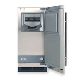
Sub-Zero 315I Planning information

Sub-Zero

Sub-Zero 315I Planning information

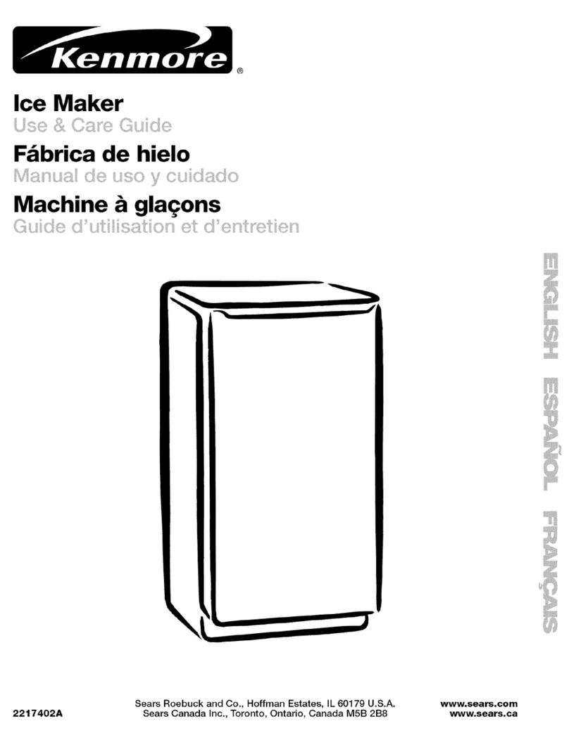
Kenmore 2217402A Use & care guide

Kenmore

Kenmore 2217402A Use & care guide

GE XPIO43SCSS owner's manual

GE

GE XPIO43SCSS owner's manual

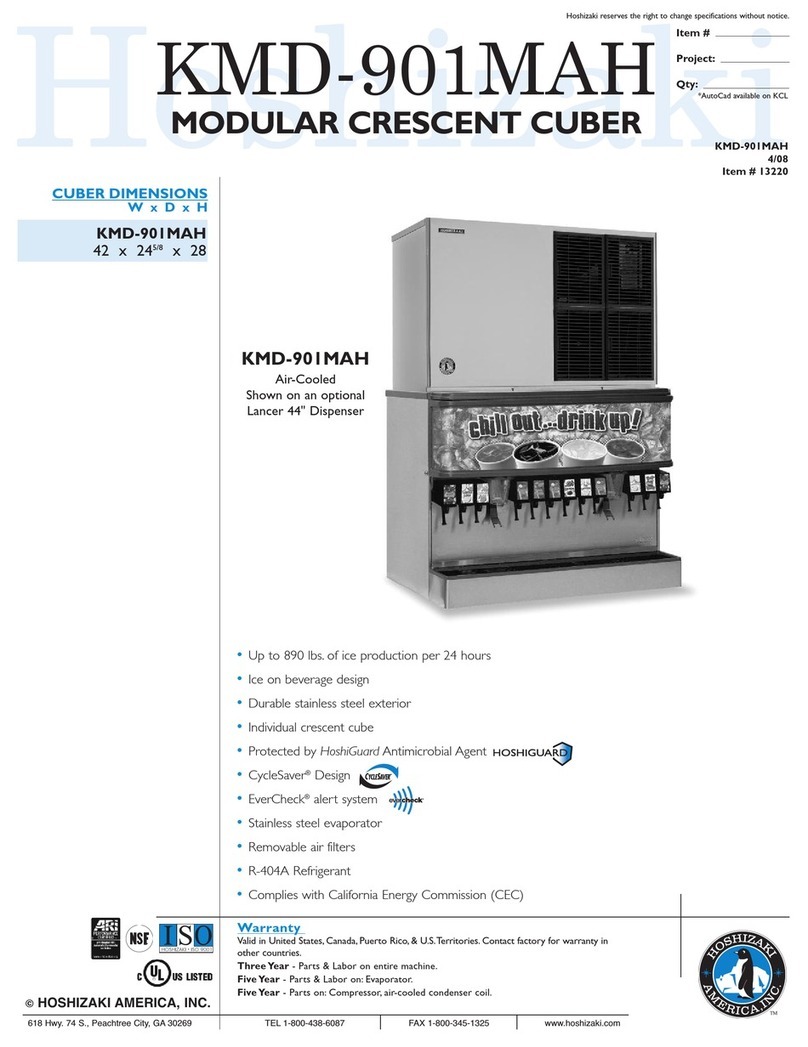
Hoshizaki KMD-901MAH Specifications

Hoshizaki

Hoshizaki KMD-901MAH Specifications

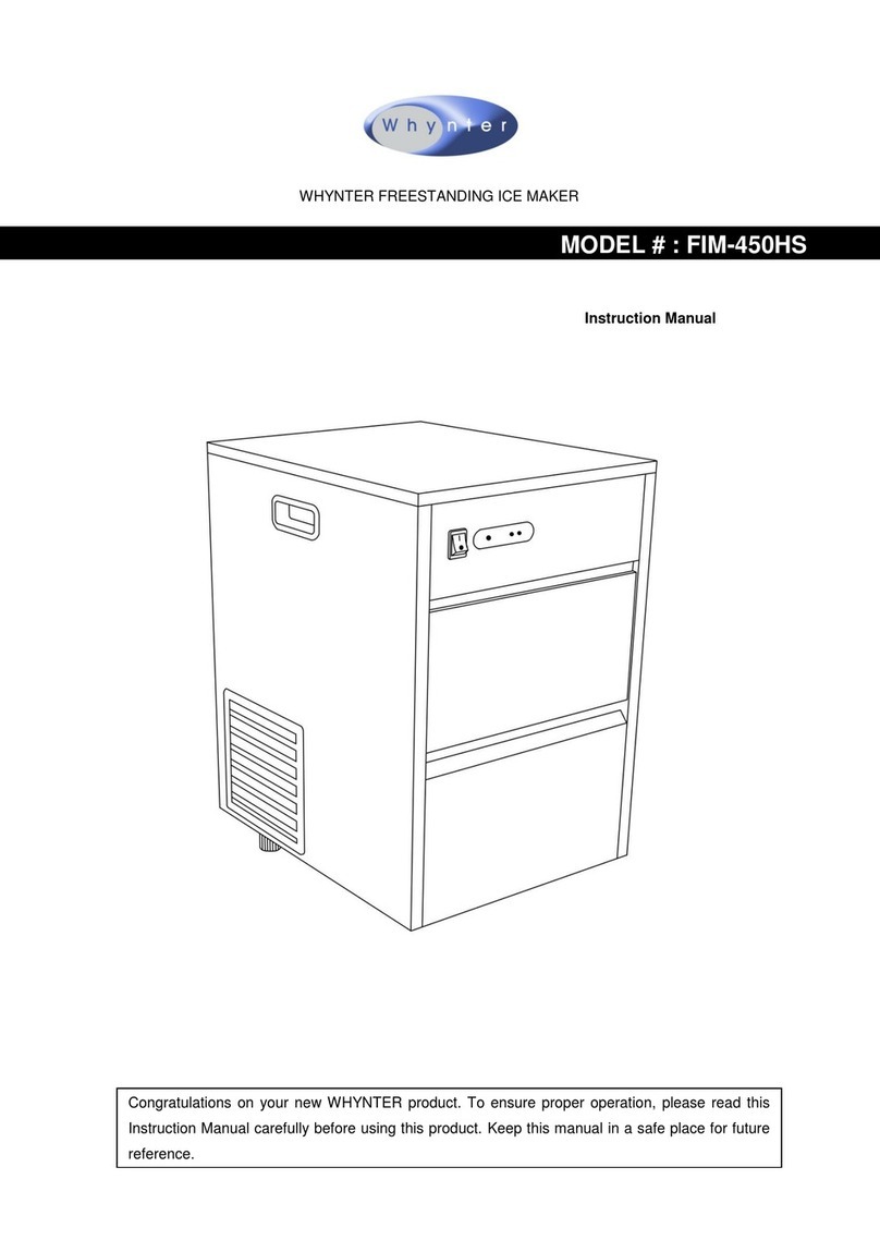
Whynter FIM-450HA instruction manual

Whynter

Whynter FIM-450HA instruction manual

Unold 48945 Instructions for use

Unold

Unold 48945 Instructions for use

Andrew James AJ000522 manual

Andrew James

Andrew James AJ000522 manual

Scotsman CME1356 user guide

Scotsman

Scotsman CME1356 user guide

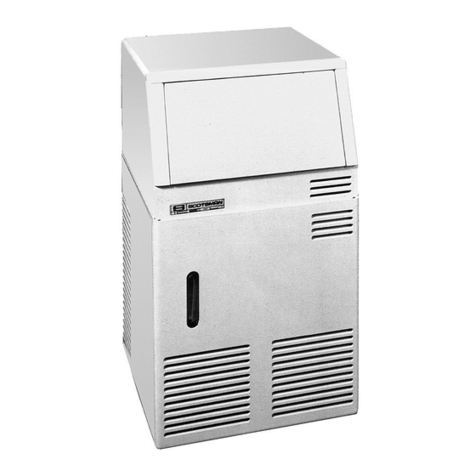
Scotsman ACM 25 Service manual

Scotsman

Scotsman ACM 25 Service manual

Kärcher IP 120 manual

Kärcher

Kärcher IP 120 manual

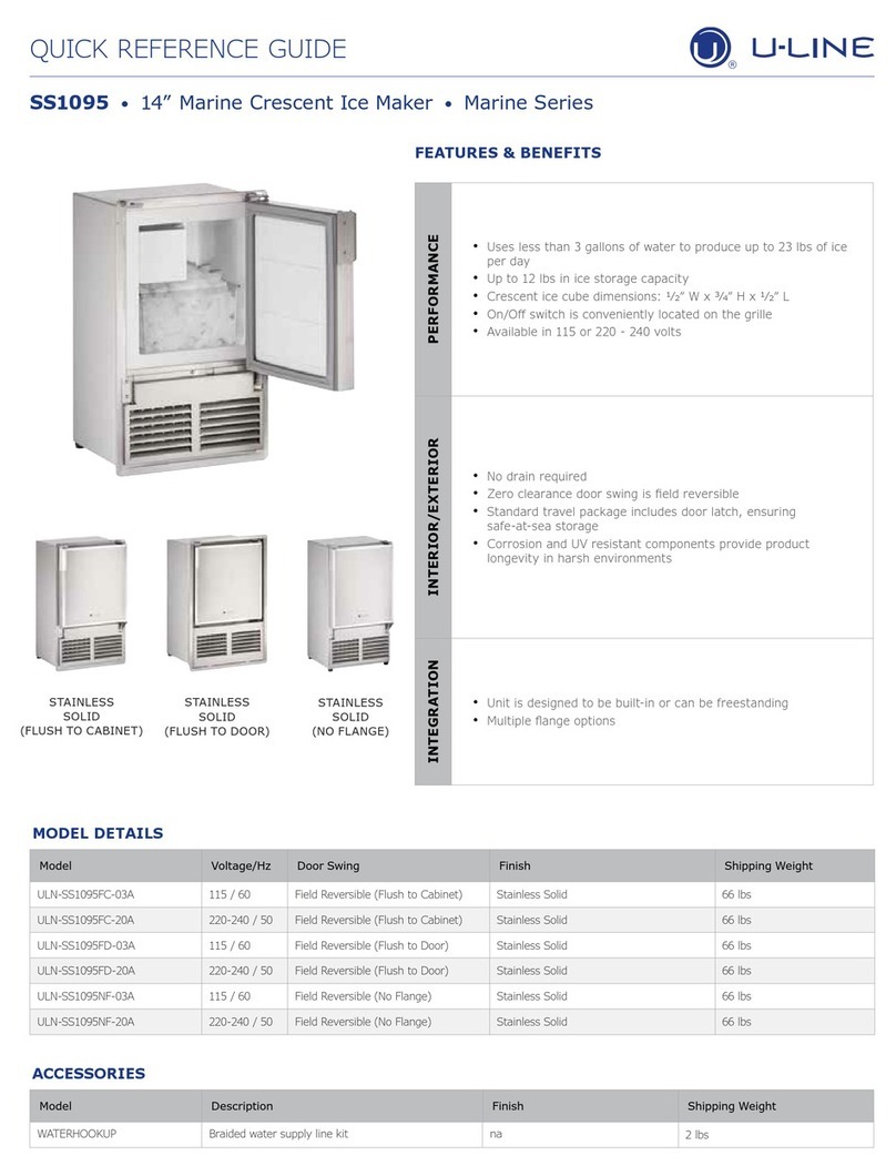
U-Line SS1095 Quick referenc guide

U-Line

U-Line SS1095 Quick referenc guide

Maytag MIM1554WRS - Ice Maker User instructions

Maytag

Maytag MIM1554WRS - Ice Maker User instructions

Igloo ICE102-WHITE user manual

Igloo

Igloo ICE102-WHITE user manual

Hoshizaki KM-630MAH instruction manual

Hoshizaki

Hoshizaki KM-630MAH instruction manual

Princess Yonanas user manual

Princess

Princess Yonanas user manual

Unold 48946 Instructions for use

Unold

Unold 48946 Instructions for use

Electrolux E15IM60GP Factory parts catalog

Electrolux

Electrolux E15IM60GP Factory parts catalog

manuals.online logo
manuals.online logoBrands
  • About & Mission
  • Contact us
  • Privacy Policy
  • Terms and Conditions

Copyright 2025 Manuals.Online. All Rights Reserved.

Service
Manual
SERIES
1400
(R-22)
MODULAR
CUBED
ICE
MAKER
12/91
161951806
1
NTRQDUCTI
ON
We
have strived
to
produce
II
quality product.
thus insuring trouble-free operation.
This
manual
has
been prepared to assist servicemen and users
with
lnfonnation
concerning installation, construction and maintenance
of
the ice making
equipment.
The
problems
of
the serviceman and user have been given special,
attention
in
the development and engineering of
our
fceniakers.
1;
If
you encounter
a
problem which
is
not covered
in
this manual; please fee1
free
to
write
or call.
When writing, please state the model
-
and
strial
number
of
the
machine.
Address
a1
1
correspondence
to:
The design
has
been kept simple,
We
will
be
happy
to
assist you 40
<any
way we cv,
I>
A
Product
of
lMl
Cornelius tnc.
One Cornelius Place
Anoka,
MN
55303-1
592
Phone 800-554-3526
Fax 612-422-3232
!
2
71
$*
I
PRINTED
IN
USA
I)
TABLE
OF
CONT'ENTS
INTRODUCTION
............................
1
TABLEOFCONTENTS
.........................
2
...
SPECIFrCATfONS
.
b
.
b
q
3
t
INSTALLATION AND START-UP
.....................
4-10
REFRIGERANT CTRCUIT REMOTE CONDENSER UNITS
...............
11
d
ELECTRICAL CIRCUIT SEQUENCE
OF
OPERATION
...............
12
ADJUSTMENT FOR ICE BRIDGE THICKNESS
.................
12
ADJUSTMENT AND CHECK-OUT FOR OPTICAL HARVEST
.
BIN SENSOR
.....
13
WIRING AND SCHEMATIC DIAGRAMS
...................
14-17
6
SANITIZING AND CLEANING PROCEDURE
...........
:
.....
18
WATERTREATMENT
..........................
19
WINTER STORAGE
...........................
20
CLEANING THE CONDENSER
...
...........
......
20
SERVICE ANALYSIS
..........................
21-23
INSTRUCTIONS FOR REMOVAL AND RE-INSTALLATION
i
..
6
...
OF SOLID STATE CONTROL
....................
24
PARTS LIST
...................
.........
25
ILLUSTRATED PARTS BREAKDOWN
....................
26
REMOTE CONDENSER ILLUSTRATED PARTS BREAKDOWN
............
27
2
Specifications
Ambient
Temp
'F
SERIES
1400
Incoming
Water
Temp
'F
50.
70' 80'
8011OY
VIEW
10'
80'
90'
70'
1400
1240 1180
1j20
1175
1110
1210 1081 1025
1420 1210 1120
Model
Number
(Corrdcnser)
(Air
*led)
[Water
Cooled)
[Remote-
Air)
COMPRESSOR ELECTRICAL RATING
.....
COMPRESSOR MODEL
...........
CONDENSER.
...............
(water
cooled).
.
(remote).
....
REFRIGERANT CHARGE
(air
copled).
..
REFRIGERANT
CONTROL
.........
TXV
SUPERHEAT SETTING
........
INLET WATER SUPPLY
..........
VOLTAGE
...............
TOTAL AMP DRAW
.....
...
CRANKCASE PRESSURE REGULA7
OR
;EiTI
IiG
.
3.25
H.P.
Air,
water
or
remote
64
02.
R-22
42
OZ.
k-22
270
OZ.
R-22
CRK3-0325-PFV
TXV
6O
3/8"
SAE
ma
208-230/60/
14.8
amps
45
PSI
Max.
e
flare
,
3
INSTALLAIION
INSTRUCTIONS
A.
UNPACKING
1.
Uncrate machine and/or bin by removing the staples from around the bottom
of cardboard crate and
lift
off.
2.
Remove bolts fastening the crate skid to the bottom
of
the unit.
auxiliary.legs have been purchased for the bin, they should be installed
at
this time.
If
8.
LEVELING
If
legs are used, adjust the leveling legs
of
the storage bin until the
unit
is
level and
all
four
(4)
legs are insolid Gontact with the
floor.
Leveling is very important
to
obtain proper dralning and to maintain the
proper level
in
the
water
pan
of
the ice
tuber*.
NOTE:
If
the bin is to be installed flush to the floor, the machine
must
be sealed to the floor with an approved mastic such *as .Sears
#3803-0
Caulk,
Dow
R.T.V.
101, 102 or
G.
E.
731,
732.
This.1~an
N.S.F.
requirement and
is the responsibility of the installer.
C.
UNIT
LOCATION
1.
Allow at least a minimum
of
six
(6)
inches at the rear and side
of
the
ice machine for proper
air
circulation.
This unit has been designed to be installed
in
an indoor location which
is clean and which can be adequately ventilated; the
air
and water
temperatures should never exceed 100 degrees nor fall below
50
degrees.
(Temperatures above 100 degrees
will
cut the ice making capacity below
an
economical level; temperatures below
50
degrees
will
cause a
malfunction of thenostatic sensors.
2.
3.
Tne unit should be located where
air
circulation
is
not restricted.
The condenser
The unit should not be located near
a
kitchen
grill.
grease vapors
will
deposit grease on the condenser.
should always be kept clean.
Air
which contains
D.
UNIT
SET-UP
1.
Take off front panel
of
machine and remove hardware bag or service
manual envelope with the water strainer enclosed.
2.
Mount the ice maker to the top
of
the ice storage bin or adapter
in
the
proper position over the ice drop opening. The ice maker must
then be sealed both on the outside and the inside bottom edges with
an approved
N.S.F.
mastic such as Dow Silastic
#732,
734
or General
Electric
RTV
#lor,
102.
responsibi
1
i
ty
of the instal
ler.
Remove shipping tape
from
evaporator curtains.
This is an
N.S.F.
requirement and the
3.
4
INSTALLATION INSTRUCTIONS CONT'D.
E. REMOTE CONDEWSERS
Remote condensers should be installed above the ice machine in a
leva1 configuration.
by
copper tubing and line valves.
is
mounted qn,tbe ice making unit and the remote condenser. The
female half is soldered on the tube ends when tubing kits are
provided with the machine.
If
tubing kits are not provided, the
female half
of
the line valves will be provided in
a
valve kit
and the installer will mount them on the tubing he provides.
They are connected to the ice making unit
The
male half of the line valve
1.
2.
3.
4.
5.
6.
PLEASE NOTE THE FOLLOWING IN REGARD
TO
REMOTE CONDENSER INSTALLATION:
WHEN MAKING LINE VALVE CONNECTIONS, LUBRICATE RUBBER SEAL IN
MALE
HALF
WITH REFRIGERATION OIL.
TOGETHER BY
HAND
TO INSURE PROPER MATING OF THREADS.
PROPER SIZE WRENCHES (ON COUPLING BODY
HEX
AND TIGHTEN UNTIL COUPLING BODIES "BOTTOM" OR A DEFINXTE
RESISTANCE
IS
FELT. USING
A
MARKER
OR
INK
PEN,
biARK
A
LINE
LENGTHWISE FROM
THE
COUPLING
HEXT
TO THE BULKHEAD. THEN
TIGHTEN
AN
ADDITIONAL
1/6
TO
1/4
TURN. THE MXSALICNMENT
OF
THE
LINE
WILL
SHOW THE DEGREE
OF
TIGHTENING.
THIS
FINAL
TURN
IS
NECESSARY TO INSURE
THAT
THE KNIFE EDGE
METAL
SEAL
BITES
INTO
THE BRASS SEAT OF
THE
COWLING HALVES FORMING THE
LEAKPROOF JOINT. IF TORQUE WRENCH
IS
USED, TORQUE TO
35
FOOT POUNDS.
I
A LOW VOLTAGE ELECTRICAL CONTROL CIRCUIT MUST
BE
FIELD
WIRES
BETWEEN THE ICE MACHINE AND THE REMOTE CONDENSER RELAY. THOSE
WIRES
SHOULD BE RUN WITH THE TUBING DURING INSTALLATION. REFER
TO APPLICABLE WIRING DIAGRAMS.
THE REMOTE ,CONDENSER REQUIRES A SEPARATE POWER SUPPLY FROM
THE
ICE MAKING UNIT. REFER TO THE REMOTE CONDENSER ON
WIRING DIAGRAM.
WHEN VERTICAL LINES
ARE
INVOLVED IN THE INSTALLATION, FOLLOW
STANDARD REFRIGERATION PRACTICES FOR VERTICAL LINES TO &XJJRE
POSITIVE OIL RETURN TO
THE
COMPRESSOR.
NO
MORE
THAN
15
FEET.
WE
DO NOT RECOMMEND TUBING RUNS OF MORE THAN
40
FEET.
THREAD COUPLING HALVES
USE
AND
ON UNION NUT)
b
VERTICAL LIFT TO BE
A THREE WAY HEAD PRESSURE CONTROL VALVE IS USED
TO
MAINTAIN
A
RELATIVELY CONSISTENT
HEAD
PRESSURE BETWEEN
180
AND
200
PSI
FOR
R-22
IN THE RECEIVER IN COLD AMBIENT CONDITIONS TO INSURE
A
GOOD HARVESTING OR DEFROSTING
OF
THE
ICE
SLABS
ON
THE
EVAPORATOR.
BE HELD IN
THE
CONDENSER.
BECAUSE
OF
THIS VALVE
SOME
LIQUID REFRIGERANT WILL
TZIE HEAD PRESSURE CONTROL VALVE WILL,NOT OPERATE CORRECTLY
WHEN
A
TOTAL PRESSURE DROP OF
14
POUNWOR
MORE
IS
CREATED
THE ICE WING UNIT UTILIZING A REMOTE CONDENSER IS SHIPPED FROM
THE FACTORY WITH THE RECEIVER HOLDING THE REFRIGERANT CHARGE.
ADDITIONAL REFRIGgRANT
MAY
BE REQUIRED UPON INSTALLATION DEPEND-
5
ING UPON THE AMBINET CONDITIONS THE REMOTE CONDENSER
IS
OPERATING UNDER, THE CONDENSER AND LINE SIZING.
F.
MAKE ELECTRICAL
POWER
SUPPLY
CONNECTION
Requirements: 208-230/60hz.
1
ph. or
220V
50hz.
1 ph. when used
REFER
TO
SERIAL
PLATE
FOR MINIMUH
CIRCUIT
AMPACITY
AND
MAXIMUM TIME
DELAY
FUSE
SIZE.
ALL
WIRING
MUST
CONFORM
TO
NATIONAL AN0
LOCAL
ELECTRICAL
CODES.
G.
MAKE
PLUMBING CONNECTIONS
Water supply
-
(Install per lscal codes)
The water inlet connection to the
unit
is
a
3/8"
flare male connections
located at the rear of the ice machine.
NOTE:
should
be
installed
in
the water inlet line between the water' shut-off valve
and the strainer.
If
the water pressure exceeds
50
pounds,
a
water
pressure regulator
Install
a
reducer fitting on the shut-off valve to aecomodate the water
strainer, which
is
supplied with each ice machine and
MUST
be used.
the water strainer with the arrow in the proper direction of flow and with
the clean out plug down, This is very important
for
cleaning. Connect
either
3/8"
or
1/2"
copper tubing between the
water
inlet fitting of the
ice machine and the water strainer.
Install
for
water cooled units, two water inlet connections are provided; one for
the ice making (evaporator) section which is located on the back
of
the
machine and is
a
3/8"
flared connection. The other is
for
the water cooled
condenser. The reason
for
the separate water inlet connections is that some
installations use
a
water tower
for
cooling the water used
in
the water-
cooled condenser and some installations use treate water (filtered) for
the ice making inlet water connection.
(incoming) to the
3/8"
male flare connection on
the
back
of
the unit that
supplies water to the water regulating valve inside.
The setting of the
water
regulating valve from the factory should be 120
pounds
for
R-12 units and
225
pounds for
R-22
units.
NOTE:
Always flush
out water lines before starting unit.
done at installation.
Provide a suitable trapped open drain as close as possible to the area where
the ice maker
is
going to be installed.
1-1/4" trapped open drain.
cooled units, one
for
the storage bin and
one
for the
hmp
Valve
drain
hose.
Be
sure to install
water
line
Adjustments.
if
necessary, should be
H.
DRAINS
This
may
be an existing floor or
a
Two separate drain lines
are
required for air
An
additional separate drain line
will
be required for
water
cooled
units
from the outlet of the condenser coil to the drain.
lines with
a
good
fall
to the open drain.
ALL PLUMBING
MUST BE INSTALLEO
IN
ACCORDANCE
WITH
LOCAL CODES.
NOTE:
IN
SOME
CASES IT
HAY
BE
NECESSARY
TO
INSULATE THE
WATER
SUPPLY LINE
AND
DRAIN
LINE CONDENSATE DRIPPING TO THE
FI,.OOR
CAN CAUSE
SERIOUS
STAINING
OF
CARPETS
OR
HARDWOOOS.
Run
all
gravity drain
6
INSTALLATION INSTRUCTIONS CONT'D.
Dclnp
Valve
drain
hose
ar
;i
Taking
care not
to
kink
or
bllapse
vinyl
tubing
at
any
point, rbute
tubs
to
any
open,
I
trapped
or
vkted Yloor
drain.
tubing
to
drain
separately.
Do
not
tee
any
drain hoses
together. Add drain
tubing
required
to
reach floor
drain.
I"
1.
ADJUSRiENT
OF
WATER LEVEL
IN
RESERVOIR
With the water supply turned
ON
and the power supply OFF'adjust
froat to maintain water levelk" below the support web insidereservoir
(See
Illustration
Below)
Reservoir drain cap
Adjust
here
Float assernb
W-,:
Ice
bi;ikcr
will
not
opcratc properly
when
w;iCcr
supply
tcmpcraturc
is
below
50'F
or
above
100'1;.
\J;itcr
supply
prcssure must not
exceed
50
PSI.
7
INSTALLATION
INSTRUCTIONS
CONT'D.
J.
STARTING
THE
UNIT
After the ice cuber has been unpacked and leveled and all plumbing and
electrical connections have been made, start the
unit
and check for proper
operation.
A
cuber has three separate circuits:
A.
The water circuit
B.
The refrigerant circuit
C.
The electrical circuit
1.
Start checking the water circuit by making sure that there are
no
thread
or flare joint leaks, either outside the unit or inthe compressor section.
Next check the water flow over the evaporator and make sure that all holes
in the water distributor are open, and that there- is no undue splash or
loss of water into the ice bin.
Also check to see
if
the float valve is functioning properly and the
correct water level is being maintained. Re-adjust
if
necessary.
Check the refrigerant circuit by making sure that the condenser fan is
running.
(Feel the casing for vibration.)
2.
(This
will
be evident by air noise.)
Is
the compressor running?
Is
the evaporator getting cold?
3-
Check bin-harvest switch operation. (See proceedure in manual)
8
STACKING
KIT
INSTALLATION
INSTRUCTIONS
FOR MODEL RCV-1204
F
1
-
43547 interface cable
1
-
43534 cover, chute to
2
-
8022 cli plastic
1
-
20928 bushng, snap
2
-
39499 strap, tie
16
-
857 screw 8/32
1
-
43535 cover, chute
bo
tom
1
-
43541 slide, ice top
ri
ht hand
1
-
43542 slide, ice top le
t
hand
1
-
43537 slide, ice
ri
ht hand
1
-
43539 slide, ice le
t
hand
9
3
PLEASE
SEE
ILLUSTRATIONS
FOR
REFERENCE
FOR
THE
FOLLOWING INSTALL
PROCEDURE:
1.
2.
3.
4.
5.
6.
7.
8.
9.
10.
11.
12.
13.
14.
15.
16.
17.
18.
After the units are mounted on each other remove evaporator
curtains
from
the bottom machine.
Drill
2 each 3/16" holes
11
inches directly above weld nuts in the
middle of the back wall of evaporator section
if
holes are not
already in postion.
Pre-assemble right and left ice slides as shown
in
illustration.
Do
not tighten screws at this time, leave roan for adjustment.
Bring ice slides thru the bin and lower machine and hang over bent
edges of the top unit water reservoirs.
Insert the plastic cli
s
and screws thru ice slide flanges into
weld nuts and drilled
R
oles on back wall of unit.
slides
from
the bottom and tighten screws securely.
Insert the bottom chute cover plate and punch a hole thru the
splash shield to insert a mounting screw thru
it
and to the bottom
weld nut of the plate.
into the weld nuts of the ice slides and tighten all screws
secure1
y.
Insert top chute cover plate up alon
match weld nuts.
tighten securely.
Push down the top ice slide sections hanging on water reservoir
bent edges and secure screws.
Make sure power is off to the units and remove electrical box
covers
from
both units.
Remove lowest grommet from the left side of each electrial box.
Remove the plug
frdm
chassis base pan of
the
tog unit in the stack.
Insert the snap bushing into the hole the plug was just removed
from.
4
String interface cable thru the snap bushing then insert the cable
thru each electrical box hole and split romets.
Reinstall grommets into electrical box,
Plug
the
interface cable onto the open DC-3 terminal on the left
side
of
each solid state control board.
Please Note: The plug connection is larized and can only go on
one way.
Replace electrical box covers.
Plug the weld nut hole found to the right of the compressor
with
a
mastic sealant.
Remove the screws from both sides of both units and insert the tie
straps. Reinstall screws.
Pull down on ice
Insert screws thru the top slots of plate
ice slide flanges until slots
Insert
5
screws
in
9
o
lower slots position and
Please Note: Make sure marked end
of
cab
9
e goes to the top unit.
be careful and make sure
o
p"
a
good connection.
9