Cornell SGH Series Troubleshooting guide

INSTALLATION INSTRUCTIONS
AND
OPERATION MANUAL
SGH Series
UL325-2010 Compliant
Commercial and Industrial Door Operator
Logic Control
Continuous Duty

1
SGH Series
REVISION # 0002
DATE: 10/09/2012
IMPORTANT INSTALLATION INSTRUCTIONS
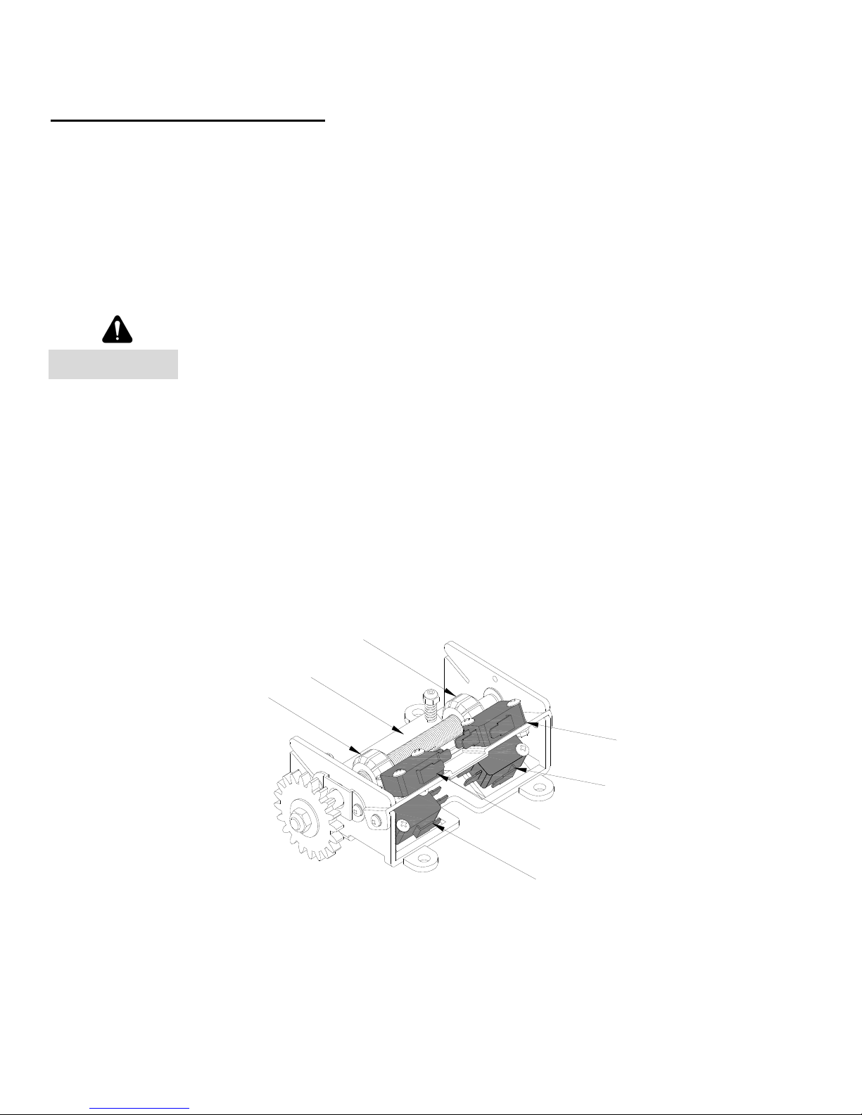
WARNING – To reduce the risk of severe injury or death to persons:
1. READ AND FOLLOW ALL INSTALLATION INSTRUCTIONS.
2. Install only on a properly operating and balanced door. A door that is operating improperly could
cause severe injury. Have qualified service personnel make repairs to cables, spring assemblies,
and other hardware before installing the operator.
3. Remove all pull ropes and remove, or make inoperative, all locks (unless mechanically and/or
electrically interlocked to the power unit) that are connected to the door before installing the
operator.
4. Install the door operator at least 8 feet or more above the floor if the operator has exposed moving
parts. If it is installed less than 8 feet above the floor, any exposed moving parts must be covered or
guarded.
5. Do not connect the door operator to the source of power until instructed to do so.
6. Locate the control station: (a) within sight of the door, (b) at a minimum height of 5 feet so small
children cannot reach it, and (c) away from all moving parts of the door.
7. Install the Entrapment Warning Placard next to the control station in a prominent location.
8. Make sure the available power supply to be connected to the operator is of the same voltage,
frequency, phase and wattage as indicated on the nameplate of the operator.
9. Read and understand the wiring diagram of the operator and the control station (open-close-stop
push button), and any other equipment to be connected to the operator.
10.To avoid damage to the door and operator, make all door locks inoperative. Secure locks in the
unlocked position, or install external electrical interlocks to prevent operation with the locks
engaged.
11.Always disconnect power whenever installing or servicing the door operator or door.
12.All wiring must be permanent and comply with National Electrical Code (NEC) and local code
requirements.
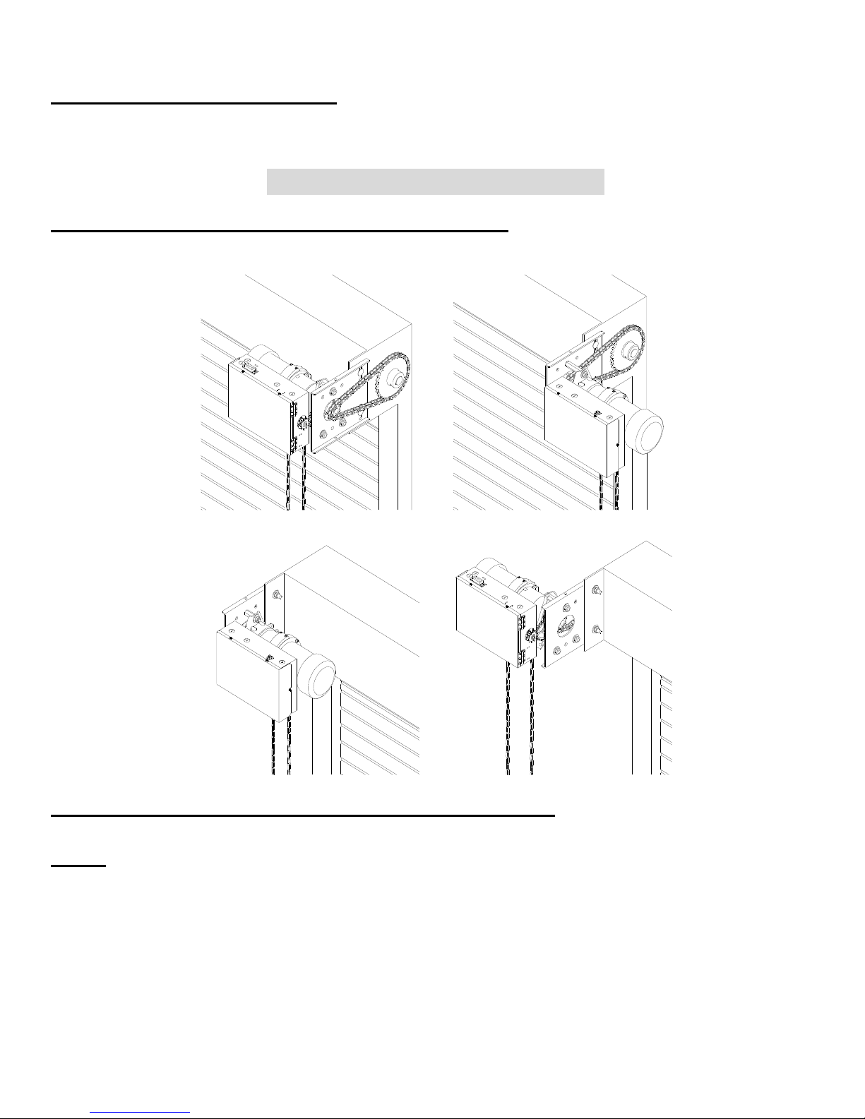
13.Any change in mounting position may result in a change of operator rotation and consequently in a
change of control functions. Consult factory for any changes.
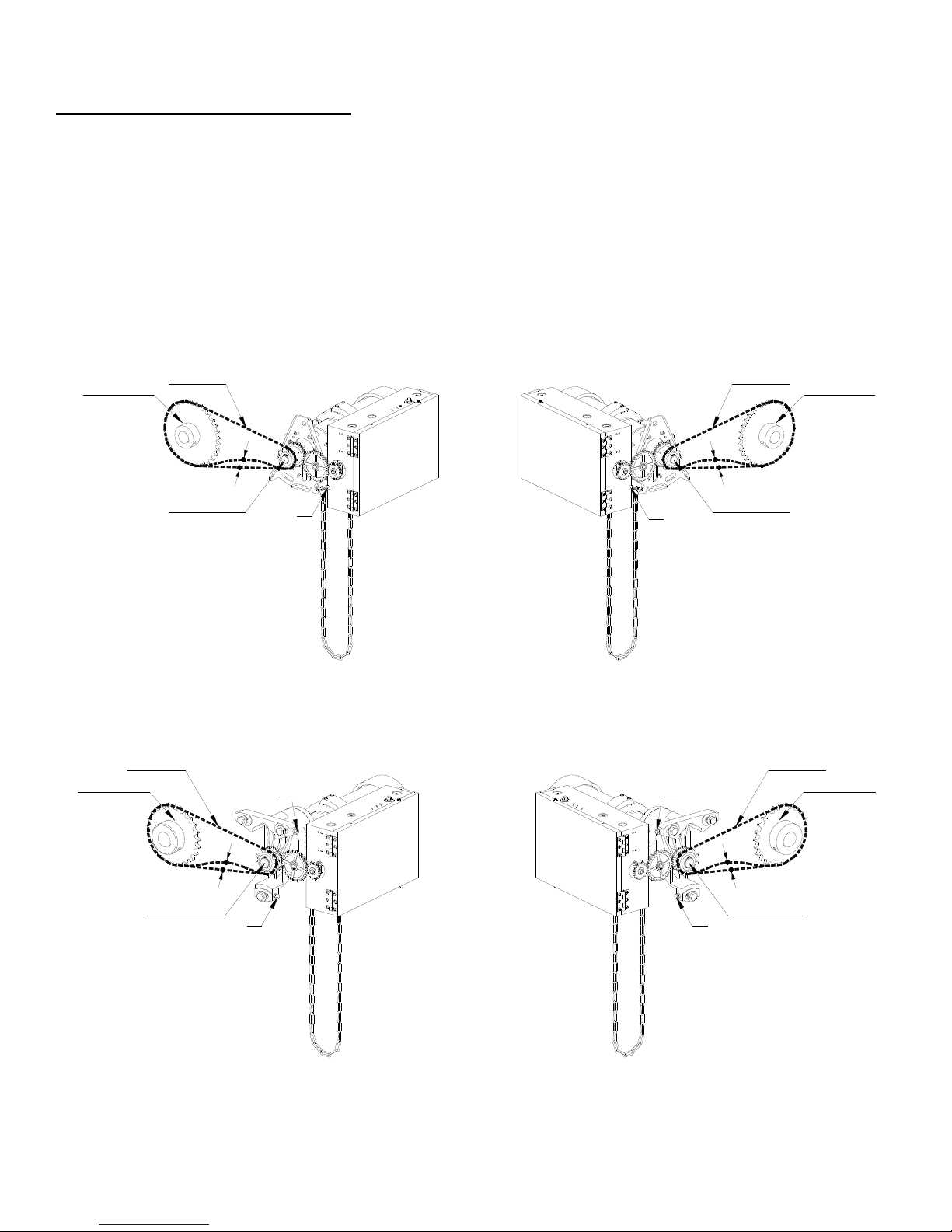
14.If the operator is provided with an auxiliary chain operator, the hand chain should be kept inside the
chain bag when operating electrically.
15.For products having a manual release, instruct the end user on the operation of the manual release.

2
SGH Series
REVISION # 0002
DATE: 10/09/2012
SPECIFICATIONS
MOTOR
Duty Cycle: Continuous duty
Horsepower: 1/2 hp, 3/4 hp, 1 hp, 1½ hp, 2 hp
Speed: 1700 RPM
Voltage: 115, 230 – 1 phase
208/230, 460, 575 – 3 phase
230 volt 3 phase motor is suitable for use with 208 volts
Current: See motor nameplate
ELECTRICAL
Transformer: 24VAC
Wiring Type: Momentary pressure open, stop, constant pressure close
(provided standard), with provision for momentary pressure close*
Limit Adjustment: Linear driven, fully adjustable screw type cams.
MECHANICAL
Drive Reduction: 43:1 (1/2 & 3/4 hp), 57:1 (1 & 1½ hp,), 82:1 (2 hp)
Output Shaft Speed: 39 RPM (1/2 & 3/4 hp), 30 RPM (1 & 1½ hp),
21 RPM (2 hp)
Door Speed: 6 - 8” per sec. average (typical)
Brake: Solenoid actuated brake
Emergency Chain Hoist: Standard
ENTRAPMENT PROTECTION
Sensing Edge*: (Optional) Sensing device attached to the bottom edge of the door.
Non-Contact Device*: (Optional) Photo eye device.
* Per the requirements of UL Standard 325, the door operator is setup for constant
pressure to close the door. As an alternative, the door may be provided with a monitored
entrapment protection device that will reverse the door upon contact with or detection of
an obstruction during closing. Adding an entrapment device would enable momentary
close operation.
*Note:
1. Non-contact device (photo eye) can be used on doors up to 45 ft. wide (or maximum rated range of
device if less than 45 ft.). Use a sensing edge to provide entrapment protection on doors over 45 ft.
wide.
2. Sensing edge can be used on all doors.

3
SGH Series
REVISION # 0002
DATE: 10/09/2012
TYPES AND SIZES OF DOORS
Consult factory for details.
INSTALLATION INSTRUCTIONS
INSTALLATION POSITIONS (for 1/2hp and 3/4hp)
RS RA
LS LA
Consult factory for changes in installation positions.
NOTE: Any change in mounting position may result in a change of operator rotation and
consequently in a change of control functions. Consult factory for any changes. (LH=LS and RA,
RH=RS and LA)
Operators mounted in alternate positions (LA, RA) require the long mounting legs in lieu of the
standard short mounting legs.

4
SGH Series
REVISION # 0002
DATE: 10/09/2012
INSTALLATION POSITIONS (for 1hp, 1-1/2hp, 2hp)
RS
LS
RA
LA
Consult factory for changes in installation positions.
NOTE: Any change in mounting position may result in a change of operator rotation and
consequently in a change of control functions. Consult factory for any changes. (LH=LS and RA,
RH=RS and LA)
Operators mounted in alternate positions (LA, RA) require a straight mounting plate in lieu of
the standard bent plate.

5
SGH Series
REVISION # 0002
DATE: 10/09/2012
OPERATOR MOUNTING
1. Before the operator is installed, verify that the door is properly operating and balanced.
2. Make sure the layout of the mounting holes on the bracket are correct.
3. Bolt the operator mounting plate to the door bracket plate.
4. Attached and tighten the three mounting legs to the mounting plate. (Not applicable for 1hp, 1½hp,
2hp)
5. Finally, mount the operator to the three legs and tighten (for 1/2 and 3/4hp only). For other
horsepowers, mount the operator to the mounting plate.
(Figure 1 for 1/2hp and 3/4hp)
(Figure 2 for 1hp and 1½hp)

6
SGH Series
REVISION # 0002
DATE: 10/09/2012
6. When the operator assembly is attached to the door bracket, be sure the door driven sprocket is
properly aligned with the operator drive sprocket before securing the driven sprocket to the shaft.
7. The shelf or bracket must provide adequate support for the operator. Prevent play between the
operator and the door shaft. The operator must be securely attached with the drive shaft parallel to
the door shaft. It may be necessary to field brace the operator/bracket.
Correct
Incorrect
Door
Sprocket
Operator
Drive
Sprocket
(Figure 1 for 1/2hp and 3/4hp)
Correct
Incorrect
Door
Sprocket
Operator
Drive
Sprocket
(Figure 2 for 1hp and 1½hp)

7
SGH Series
REVISION # 0002
DATE: 10/09/2012
DRIVE CHAIN ADJUSTMENT
NOTE: Use correct type, size and proper length of roller chain.
1. Adjust the drive chain by tilting or move the operator so that there is about 1/4” of slack when the
chain is depressed.
Note: The set screw included in the operator may be used for adjustment. (See figure 1- S1 location for
1/2hp and 3/4hp), (See figure 2 - T1, T2, T3, T4 for 1hp and 1½hp).
2. Once the drive chain has been tightened and the base leg screws have been set, and then tighten the
operator screws.
S1
Drive Chain
Door Sprocket
Drive Sprocket
1/4"
S1
Drive Chain
Door Sprocket
Drive Sprocket
1/4"
(Figure 1 for 1/2hp and 3/4hp)
Drive Chain
Door Sprocket
Drive Sprocket
1/4"
T1
T2
Drive Chain
Door Sprocket
Drive Sprocket
1/4"
T3
T4
(Figure 2 for 1hp and 1½hp)

8
SGH Series
REVISION # 0002
DATE: 10/09/2012
HAND CHAIN ADJUSTMENT
Cut and reconnect chain with different color link provided.
Chain Holder
Optional

9
SGH Series
REVISION # 0002
DATE: 10/09/2012
LIMIT SWITCH ADJUSTMENT
Make sure the limit cams are positioned between the limit switch actuators before proceeding
with adjustments.
1. Open / Remove the control panel cover.
2. Open or close door to determine the moving direction of the limit switch cams.
3. Open or close door to the desired position.
Disconnect power before adjusting limit switch cams.
4. While pressing the spring-loaded lever (G), which holds the limit switch cams in place, adjust the limit
switch cam (E or F) until the micro switch (C or D) clicking sound is heard.
5. If the limit switch cam cannot be rotated to its desired position, release the lever and move the door
away from the desired position, then adjust the limit switch cam to its desired position. It may be
necessary to repeat this step until the exact position has been reached.
6. Repeat step 3 and 4 for the opposite position. Adjust close limit cams so that actuator is engaged as
door fully seats at the floor.
7. Micro switch (A or B) can be adjusted to accommodate sensing edge cut-off position.
A
D
B
C
F
G
E
NOTE: “C” is usually the opening side and “D” is usually the closing side.
WARNING

10
SGH Series
REVISION # 0002
DATE: 10/09/2012
WIRING INSTRUCTIONS
Disconnect power at the fuse box before proceeding with any wiring.
1. Do not install any wiring or attempt to run this operator without checking the wiring diagram located
on the inside of the control box cover.
2. Do not turn on power until you have finished making all power and control wiring connections.
3. Do not run power and control wiring in the same conduit.
4. Any wire connected to the control panel must be protected by conduit or other means to ensure the
safety and permanency of the wiring.
5. Use copper wire inside the control panel.
6. A separate circuit of adequate capacity is needed for the operator.
7. The operator must be properly grounded. The ground screw, painted green, is located inside the
control panel.
Failure to properly ground the operator could result in electric shock and
serious injury or death.
To avoid damage to door and operator, make all door locks inoperative.
Secure lock(s) in the unlocked position, or install electrical interlocks to
prevent operation with the lock engaged.
WARNING
WARNING
WARNING

11 SGH Series
REVISION # 0002
DATE: 10/09/2012
CONTROL WIRING
If the door is not visible from the control station, or if any device other than
the control station is used to activate the door, an entrapment protection
device must be installed on the door. Failure to install an entrapment
protection device may result in serious injury or death to person(s) trapped
beneath the door.
1. Complete limit switch adjustments before making any sensing edge/non-contact device wiring
connections to the operator.
Sensing Edge
Photo Eye
6" max. above floor
Entrapment Device Options:
Sensing Module Device Manufacturer Model
ELR
2-wire resistive
sensing edge
Miller Edge Inc.
* End of Line resistor type
edge must have model
number with Suffix T2.
ME110*, ME111*, ME120*, ME123*, ME112*, ME113*,
ME116*, ME117*
MT21*, MU21*, MT22*, MU22*, MC22*, MU33*, MC271*,
CPT223*
MEL
ASO GMBH GE125, GE225
IR
Monitored photo
eye
Martec Access Products. Inc. 1266
FRABA Inc. Optical Edge Sensors and Photo Eyes, Models OPTOEDGE,
OPTOEYE; Part Nos. OSE-T, OSE-R, OSE-P, OPE.
Note: Please refer to sensing device manufacturer for specific installation and maintenance requirements.
WARNING

12
SGH Series
REVISION # 0002
DATE: 10/09/2012
Disconnect power at the fuse box before proceeding with any wiring.
2. Locate the control station where the user can
clearly see the operation of the door. Mount the
enclosed placard adjacent or near the door.
Controls shall be far enough from the door, or positioned such that the user
is prevented from coming in contact with door while operating the controls.
3. Do not run control wiring in the same conduit as power wiring.
4. Any wire connected to the control panel must be protected by conduit or other means to ensure the
safety and permanency of the wiring.
Do not use radio controls with your operator unless some type of
entrapment protection device has been installed. Failure to do so may result
in serious injury or death to person(s) trapped beneath the door.
Changing from left hand to right hand or vice versa could result in change
of control wiring. Consult factory for details.
5. After installation, be sure that the operator, controls, and sensing edge or other entrapment
protection devices have been tested and function properly.
WARNING
WARNING
WARNING
WARNING
5 ft.

13
SGH Series
REVISION # 0002
DATE: 10/09/2012
A. Control Overview:
On
Off
Timer
TIMER
M.OP
ON
OFF
M.CL
E.OP
On: Momentary Pressure
Off: Constant Pressure
Open
Close
On
Off
Auto Open
Safety Switch
ON
OFF
ON
OFF
ON
OFF
1
A. A-2.
23478910
2324P5P6E5E6
L1L2
L1L2
1.Stop
2.Open
3.Close
4.Com
7&8 Close
Warning
signal
24VAC Single-phase power source
See operator plate for correct
voltage.
A-1.
A-3.
123478910
2324P5P6E5E6
IR: P5&P6 ELR:E5&E6
(ELR-End of line resistor).
L1L2L3
Three-phase power source
See operator plate for correct
voltage.
A-3.
On: Momentary Pressure
Off: Constant Pressure
9&10
External Interlock
23&24
Timer Defeat

14
SGH Series
REVISION # 0002
DATE: 10/09/2012
B. Auxiliary Function:
Open door
Stop door
Close door
R3 R2 R1
R1 R2 R3
Radio control
GND
Push button
24VDC
B. B-1.
B-2.
B-3.
1 2 3 4
1. 1&2 Close limit dry contact
2. 3&4 Open limit dry contact
1 21 2
CN12 CN13 CN14
SE
24VDC MAX0.5A
+ -

15
SGH Series
REVISION # 0002
DATE: 10/09/2012
C. Timer Instruction:
Note: To enable timer(s) –
1) Must switch Timer Switch to ON. (See figure A-2 on Page 13 for location.)
2) Must remove jumper on Terminal PCB-CN2 (23,24). (See figure A-1 on Page 13 for location.)
C.
SELECT UP DOWN SET TIMER RESET
Timer 3
Door Open Warning
dry contact
Timer reset, press for 5 sec.
Set, press for 5 sec.
Down, decrease time.
Up, increase time.
Select, to select timer set.
C-2.
C-1.
CN8
BUZZER
LED9
SAFE
(1) Timer1–Mid‐opentimer:Timerstartscountingwhendoorleavescloselimit.Doorstopsafter
openingforsettime.Pressingopenagainatmid‐openpositionwillcausedoortoopento
openlimit.
Timer2–Timertoclose:Timerisactivewhendoorstopsandisnotatcloselimit.
Timer3–DoorOpenWarningTimer:Timerisactivewhendoorleavescloselimit.
Whentimeisup,contactwillclose.SeefigureC‐1.
TimerLED–islitwhenavalueisset.TimerLEDflashingwhencountingdown.LED12,LED13&
LED14.
Termin als9and10Externaltimerdisableswitchconnection–jumptodisablealltimerfuntionsor
installaswitchbeteen9and10.Whenswitchisopenalltimersareenabledandwhenswitchis
closedalltimersaredisabled.

16
SGH Series
REVISION # 0002
DATE: 10/09/2012
(2) StandardMode:Use toviewtimersetting;
auto‐returntocyclecountersetting
after5seconds.
(3) ToSetTimer1(Mid‐openTimer):
zPress andholdfor5seconds.Displaywillflash.
zUse and toincreaseortodecreasetime.
zPress andholdfor5secondstoconfirmsetting.Withoutpressingandholding
for5seconds,noadjustmentisconfirmed.
SELECT UP SET TIMER RESETDOWN
TIMER 1
TIMER 2
TIMER 3
COUNTER
5 Seconds
TIMER 1
TIMER 2
TIMER 3
COUNTER
SELECT UP SET TIMER RESET
DOWN
For save
Mid-Open Timer
Set the
desired time.
Press SET until Timer 2 light is lit.
Continue to set Timer 2 or
no action until counter light is lit.
SE LE CT UP SE T TIME R RESET
DOWN
TIMER 1
TIMER 2
TIMER 3
COUNTER
Min. 1 Sec
Max.99 Sec
SE LECT UP SET T IMER RESETDOWN
TIMER 1
TIMER 2
TIMER 3
COUNTER
Min. 1 Sec
Max.99 Sec

17
SGH Series
REVISION # 0002
DATE: 10/09/2012
(4) ToSetTimer2(Timertoclose):
zSwitchM.CLswitchtoON. (SeefigureA‐2onPage13forlocation.)
zUseand toincreaseortodecreasetime.
zPressandholdfor5secondstoconfirmsetting.Withoutpressingandholding
for5seconds,noadjustmentisconfirmed.
TIMER 1
TIMER 2
TIMER 3
COUNTER
SELECT UP SET TIMER RESETDOWN
Timer to Close
Press SET until Timer 3 light is lit.
Continue to set Timer 3 or
no action until counter light is lit.
For save
Set the
desired time.
SE LECT UP SE T T IMER RESETDOWN
TIMER 1
TIMER 2
TIMER 3
COUNTER
Min. 1 Sec
Max.99 Sec
SELECT UP SET TIMER RESETDOWN
TIMER 1
TIMER 2
TIMER 3
COUNTER
Min. 1 Sec
Max.99 Sec
(5) ToSetTimer3(BuzzerTimer):
zUse and toincreaseortodecreasetime.
zPress andholdfor5secondstoconfirmsetting.Withoutpressingandholding
for5seconds,noadjustmentisconfirmed.
TIMER 1
TIMER 2
TIMER 3
COUNTER
SELECT UP SET TIMER RESETDOWN
Press SET until Timer 1 light is lit.
Continue to set Timer 1 or
no action until counter light is lit.
For save
Set the
desired time .
SELECT UP SE T TI M E R RESETDOWN
TIMER 1
TIMER 2
TIMER 3
COUNTER
Min. 1 Sec
Max.99 Sec
SELECT UP SET TIMER RESET
DOWN
TIMER 1
TIMER 2
TIMER 3
COUNTER
Min. 1 Sec
Buzzer Timer
Max.09 min 59 Sec

18
SGH Series
REVISION # 0002
DATE: 10/09/2012
(6) Toconfirmtimervalue:
SELECT UP SET TIMER RESETDOWN
TIMER 1
TIMER 2
TIMER 3
COUNTER
SELECT UP SET TIMER RESETDOWN
TIMER 1
TIMER 2
TIMER 3
COUNTER
Set Mode Set Mode
SELECT UP SET TIMER RESETDOWN
TIMER 1
TIMER 2
TIMER 3
COUNTER
SELECT UP SET TIMER RESETDOWN
TIMER 1
TIMER 2
TIMER 3
COUNTER
Set Mode
Select Timer
Note: To enable timer(s) –
1) Must switch Timer Switch to ON. (See figure A-2 on Page 13 for location.)
2) Must remove jumper on Terminal PCB-CN2 (23,24). (See figure A-1 on Page 13 for location.)

19
SGH Series
REVISION # 0002
DATE: 10/09/2012
D. Light Indication:
LED14 Door open timer
ON : Lit-Timer is set.
Flashing-Counting
time.
OFF: No setting.
LED3 Door open limit
ON: Door at open limit.
OFF: Not at open limit.
LED5 AUX close Limit contact
ON: Door at AUX close limit.
OFF: Not at AUX close limit.
LED4 Door close limit
ON: Door at close limit.
OFF: Not at close limit.
LED1 Control station open
ON: Door is opening.
OFF: Door not open.
LED2 Control station close
ON: Door is closing.
OFF: Door not close.
LED9 Obstruction
ON: Any one sensing
device is activated.
OFF: Not activated.
LED10 IR
ON: Connected with IR.
OFF: Not connecting or
damaged IR.
LED26 Close warning signal
ON: Door is closing.
OFF: Not activated.
LED6 ELR
ON: Connected with ELR.
OFF: Not connecting or
damaged ELR.
LED8 Device light
ON: Sefety device
disconnected, failed
or damaged.
OFF: When any one of
sensing device is
normal.
LED17 Open button
ON: Activated
OFF: Not activated
LED18 Close button
ON: Activated
OFF: Not activated
LED16 Control Station stop
ON: Connect with 3 button
control station and not
activate STOP button.
OFF: Not connect with 3
button control station
or activate STOP
button.
LED12 Mid open timer
ON : Lit-Timer is set.
Flashing-Counting
time.
OFF: No setting.
LED13 Close timer
ON : Lit-Timer is set.
Flashing-Counting
time.
OFF: No setting.
LED15 Counter
ON: Display cycle counter.
OFF: When setting is not
at counter position.
LED27 Open limit contact
ON: Activated.
OFF: Not activated.
LED19 Close limit contact
ON: Activated.
OFF: Not activated.
10 26 6
9
8
11 19 27
1
218
17
19
3
5
4
12
13
14
15
LED11 N/O type sensing edge.
ON: Sensing device is activated.
OFF: Not activated.
Table of contents