CORNING Falcon 357469 User manual

Falcon® Pipet
Controller
Instruction Manual
Catalog Numbers:
357469
357471

2 3
F
G
H
JA
E
B
K
L
12
DC
DC
1
2
3
4 5
3AC
B
4
5 6
1234
B C D
A
B7A7
7
8
F
G
H
M
L
N
A – Aspiration button – PP
B – Dispense button – PP
C – Suction speed switch – PP
D – Dispense mode switch – PP
E – Display
F – Nose piece – PP
G – Pipet holder – SI
H – Membrane lter – PP / PTFE
J – Connector gasket – SI
K – Batteries cover – PP
L – Battery – NiMH, AAA, 1.2V
M – Charging stand – PP
N – Charger 9V: EU, US, UK, AU
INPUT: 100-240V, 50/60Hz, 0.3A
OUTPUT: AC DC 9V, 230mA
Casing – PP
PP: Polypropylene
PTFE: Polytetrauoroethylene
SI: Silicone

4 5
1. Introduction
The Falcon® pipet controller is a device intended for pipetting liquids with the use of
measuring pipets. It can work with all types of glass or plastic pipets in the volume range
from 0.5 mL to 100 mL.
Two dispense modes permit selection of dispensing intensity depending on the user’s
needs. The selected setting of the pipet controller mode is shown on the display (Figure 1E).
Figure 1 shows the external parts of the pipet controller with a description of the materials
used. Display indicators are shown in Figure 2.
2. Work Safety Instructions
WARNING! Risk of injury
CAUTION: Risk of damage to the device or errors in pipetting of liquids
Before starting the work with the pipet controller every user should read these operating
instructions carefully.
CAUTION:
• Using the device inconsistently with the operating instructions may result in damaging
the device.
• The device should be maintained only at an authorized service center, otherwise
the manufacturer will be relieved from any liability under the warranty.
• Only original spare parts and accessories recommended by the manufacturer shall be used.
• Only the original charger supplied by the manufacturer shall be used for charging
the batteries.
• Do not use the pipet controller if it is not working properly. The device should be cleaned
in accordance with the operating instructions and/or sent for repair to an authorized
service center.
• In the case of mechanical damage to the casing, the device shall be immediately sent
for repair to an authorized service center.
• The use of excessive force during work shall be avoided.
WARNING!
• While working with the pipet controller general safety regulations regarding risks
related with laboratory work should be observed. Protective clothing, goggles,
and gloves should be worn.
• The pipet controller shall be used only for measuring liquids in conditions specied
by the manufacturer, which are limited due to the chemical and mechanical resistance
of the device, as well as the user safety.
• The information and instructions provided by the manufacturers of the reagents must
be observed.
3. Limitations of Use
• The pipet controller should not be used for measuring substances, the vapors of which
damage the following plastics: PP, SI, EPDM, POM.
• The pipet controller should not be used in an environment where explosion risk
is present.
1. Introduction ...............................................................................................................................................5
2. Work Safety Instructions...................................................................................................................... 5
3. Limitations of Use ...................................................................................................................................5
4. Turning on the Falcon® Pipet Controller .......................................................................................6
5. Aspirating and Dispensing Liquids.................................................................................................. 6
6. Troubleshooting .......................................................................................................................................7
7. Replacing the Filter .................................................................................................................................8
8. Battery Charging Procedure................................................................................................................8
9. Maintenance..............................................................................................................................................9
10. Components ........................................................................................................................................... 10
11. Ordering Information ......................................................................................................................... 10
12. Spare Parts for Cat. Nos. 357469 and 357471 ........................................................................ 10
13. Limited Warranty.................................................................................................................................. 11
14. Equipment Disposal............................................................................................................................ 11
Table of Contents

6 7
• Flammable liquids should not be measured, in particular substances with ash-point
below 0°C (ether, acetone).
• The pipet controller should not be used for drawing acids with a concentration above 1 mol/L.
• The pipet controller should not be used for drawing solutions with a temperature
above 50°C.
• The pipet controller should be operated in the temperature range from +10°C to +35°C.
• The pipet controller is suitable for general laboratory use only. It must be used only by
personnel who know the health risks associated with the substances that are normally
used with this instrument.
4. Turning on the Falcon® Pipet Controller
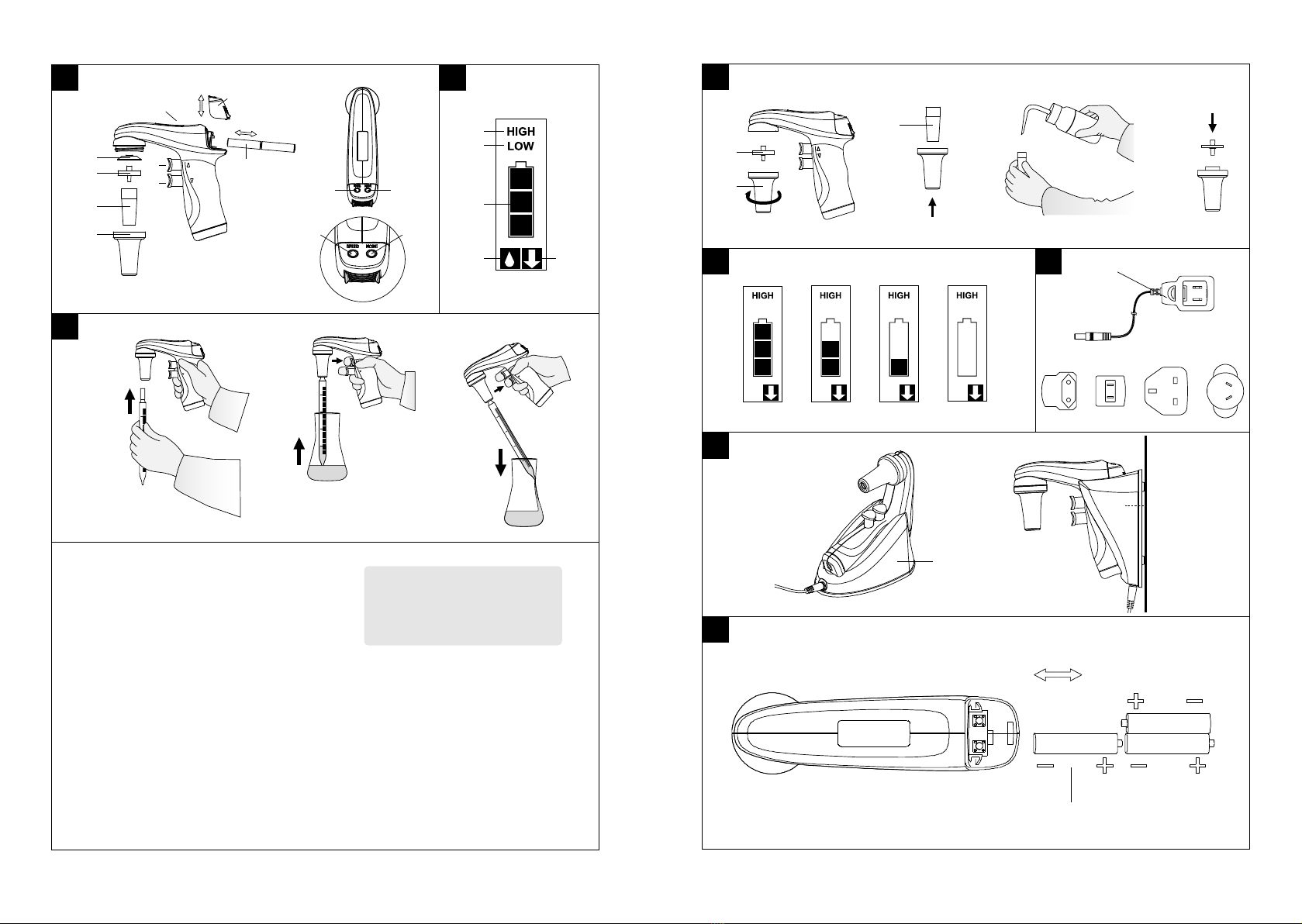
The pipet controller is switched on by pressing any of the buttons (Figures 1A, B, C, D).
The display will show the selected aspiration mode, dispense mode, and the battery level
indicator (Figure 2.3). Examples of the display indications are shown in Figure 5. The battery
is discharged and requires charging if the indicator displays one “bar” (Figure 5.3).
The batteries need to be recharged if the indicator does not display “bars” (Figure 5.4).
When the batteries are fully charged, the indicator displays three “bars” (Figure 5.1).
• The pipet controller will switch off automatically if not used for 5 minutes.
• The pipet controller should be charged only with the original charger.
• The main voltage should conform to the specication on the charger.
• Charging should be done in accordance with section 8 of this instruction for use.
5. Aspirating and Dispensing Liquids
Attaching a pipet
CAUTION: Before attaching a pipet, check to ensure the pipet is not damaged, has no
dents or sharp edges in the gripping section. Check to ensure the gripping section is dry.
The pipet controller should be gripped as close to the upper end as possible and
carefully inserted into the pipet controller holder until resistance is felt (Figure 3A).
Do not apply excessive force, to prevent damage to thin pipets controller and to avoid
injury risk. A pipet that has been correctly attached and sealed in the holder should
not tilt to the side.
After attaching a pipet, hold the device in such a way as to keep the pipet controller
in a vertical position with an attached pipet. When not in use, it is not recommended
to leave the pipet attached for long periods, for example overnight or over a weekend.
NOTE: Do not rest the pipet controller on the bench if there is liquid in the pipet.
Filling the pipet
Before aspirating is started, set the suction speed switch using the HIGH/LOW switch
(Figure 1C):
• HIGH position: fast aspirating (Figure 2.1)
• LOW position: slow aspirating (Figure 2.2)
It is recommended to choose the LOW position for pipets with a volume up to 5 mL,
and the HIGH position for pipets with a volume greater than 5 mL.
Holding the pipet controller vertically, immerse the pipet end in the liquid to be drawn
up (Figure 3B), and press the aspiration button gently. The pipet lling speed depends
on the pressure applied to the aspirating button. The greater the pressure applied,
the faster the liquid is aspirated into the pipet.
It is recommended to draw a slightly larger liquid volume than required (due to meniscus
above the required volume mark), reducing the aspiration speed, particularly in the nal
lling stage, so as not to overll the pipet.
Setting the Volume
After lling the pipet, the end should be dried with an absorbent paper that will not
leave impurities, in order to remove any excess solution on the outside surface of the
pipet. To set the required liquid volume precisely, press the dispense button gently
(Figure 3C), dispense the excessive liquid from the pipet until the meniscus of the liquid
aligns exactly with the required volume mark on the pipet.
Emptying the Pipet
Holding the vessel in an angled position, place the pipet end in contact with the vessel
wall and press the dispense button gently (Figure 3C). The dispensing intensity may
be adjusted depending on pressure applied to the dispense button. The greater the
pressure applied, the faster the outow of liquid from the pipet.
The pipet controller has two dispense modes. The dispense mode is selected with the
BLOW/GRAV switch (Figure 1D).
• Gravity mode marked with the icon on the display (Figure 2.4): Dispensing is effected
in gravity mode, which means that the liquid ows out of the pipet by its own weight.
• Blow out mode marked with the icon on the display (Figure 2.5): Dispensing is
effected in gravity mode; however, when the dispense button is pressed to the middle
position, the pump is started and fast emptying of the pipet with a blow out is affected.
CAUTION: During gravimetric dispensing the pipet may not be completely emptied due
to the characteristics of pipets used with the pipet controller.
6. Troubleshooting
If during your work the pipet controller is not functioning correctly, check the cause
and correct the fault.
Problem Possible Cause Action
The pipet falls out
(the holding force of
the pipet is too small),
or tilts to the side too
much.
The pipet holder (Figure 1G)
is dirty or wet.
Take out the pipet holder,
and clean, wash, and dry it.
The pipet holder is damaged. Replace the pipet holder
with a new one.
The pump is working,
but the pipet control-
ler aid does not draw
liquid or draws liquid
very slowly.
The lter (Figure 1H) is dirty.
Take out the pipet holder,
take out the lter; if it is
dirty, replace it with a new
one.
The pipet holder and/or the
connector gasket (Figure 1J) is
damaged.
Replace the mechanically
damaged elements with
new ones.

8 9
Problem Possible Cause Action
Liquid leaks from the
pipet (the aspiration
and the dispense
buttons are not
pressed).
The pipet is damaged.
Check the pipet for damage
(cracks, dents); if present,
replace the pipet with a new
one.
The pipet is inserted
incorrectly.
Check whether the pipet
has been correctly inserted
in the pipet holder.
The pipet holder, the lter,
or the connector gasket is
installed incorrectly.
Check whether all parts
are present and correctly
installed.
The pipet holder and/or the
connector gasket is damaged
(Figures 1G, 1J).
Replace the mechanically
damaged elements with
new ones.
If the above actions do not remedy the incorrect functioning of the pipet controller,
the device should be sent to the nearest authorized service center.
Before being serviced, the pipet controller should be cleaned and decontaminated.
Written details including the precise specication of solutions used and the type
of laboratory in which the device was used, should be sent with the product.
7. Replacing the Filter
NOTE: The work safety instructions given in section 2 should be observed when
disassembling the pipet controller.
The lter replacement is necessary if drawing efciency deterioration is observed. The direct
reason may be a dirty lter after a long period of use. The procedure is shown in (Figure 4).
• Remove the pipet.
• Unscrew the nose piece (Figure 4A).
• Remove the membrane lter (Figure 4A) and the pipet holder (Figure 4B).
• Rinse the holder using a wash bottle (Figure 4C).
• Blow liquid out of the holder and set aside until it is completely dry.
• Install the new membrane lter (Figure 4D), and assemble the device in reverse order.
8. Battery Charging Procedure
The pipet controller may be charged only with the original charger. The main voltage
must conform with the specication on the charger.
NOTE: Using other chargers than the original one may damage the battery of the pipet
controller.
Charging the battery in the pipet controller is controlled by a time circuit which controls
the entire process. When the battery has been fully charged, the charging circuit
disconnects automatically.
The pipet controller comes with 3xAAA, NiHM batteries. In order to prolong the battery
life span please consider the following:
• Before the pipet controller is activated for the rst time the battery should be charged.
• Full battery charge allows for approximately 6 to 8 hours of continuous work.
• Allow the battery status to come down to 1 bar before charging the battery.
• Frequent and/or incomplete charging will shorten the battery life.
• Charge overnight to avoid process disruptions.
• When low battery level is indicated, you can continue to work while charging.
• Condition the battery every month. This is done by allowing the battery to discharge
completely, then charging it up to full (charge overnight to avoid process disruptions).
• If the pipet controller will not be used for several weeks, charge the battery fully,
remove it from the equipment, and store it separately.
• Never mix batteries of different manufacturers, capacity, type (i.e., NiCd, NiMH, Li-ion),
or usage time (old with new).
• When needed, be sure to have a replacement set of batteries available.
• Never use a battery that is damaged or leaking.
Charging Conditions:
1. Charging temperature: 10°C to 35°C.
2. Charging the battery is carried out through a charger (power supply) by direct
connection to the power source, or indirectly by means of a charging stand
(Figure 1M). Battery charging is indicated by successive lighting of “bars” in the
display order 4-3-2-1-4-3-2-1 (Figure 5).
3. Full charging time: 7 to 8 hours.
4. The batteries are charged when all 3 “bars” are displayed simultaneously (Figure 5.1).
9. Maintenance
Cleaning
The external parts of the pipet controller may be cleaned with a swab moistened
with isopropyl alcohol.
The nose piece and the pipet holder may be autoclaved at 121°C for 20 minutes. After
autoclaving, allow the silicone pipet holder to cool. The lters included in the set may be
sterilized by autoclaving at 121°C for not more than 15 minutes.
Ultra violet (UV) sterilization
The outer body of the pipet controller is UV-resistant, however the recommended distance
from the radiation source to the exposed element should not be less than 50 cm.
Prolonged and very intense UV exposure can cause decoloration of pipet controller
parts, without affecting its performance.
Storage
The pipet controller should be stored in a dry place. Recommended storage
temperature: -20°C to +50°C.
When not in use, the pipet controller should be placed in the charging stand included
with the pipet controller (Figure 7A, B).
NOTE: Do not store the pipet controller with a lled pipet.

10 11
10. Components
The pipet controller set is supplied with the following components:
• Universal charger with set of adapters
• Charging stand
• Membrane lter 0.2 μm
• Instruction manual
11. Ordering Information
The Falcon® pipet controller (Corning Cat. Nos. 357469 and 357471) comes with
a universal charger and a set of adapters in different versions: EU, US, UK, and AUS
(Figure 6). Choose your country’s adapter and connect to the housing.
To mount the adapter, it should be inserted into the slots of the housing until you hear a click.
To remove or change the adapter, simply press the “PUSH” button in the direction of the
arrow, then holding the button down, remove the adapter in the direction of the arrow.
12. Spare Parts for Cat. Nos. 357469 and 357471
Item in Figure 1 Description Corning Cat. No. Qty/Pk
F Nose cone 357476 1
G Silicone pipet holder 357474 1
HPTFE lter 0.2 μm 357472 5
PTFE lter 0.45 μm 357473 5
L Battery set, 3xAAA, NiHM 357486 3
N
Universal power supply, 9V
with set of adapters EU, US,
UK, AUS
357489 1
M2-Position charging stand 357490 1
K Battery cover 357488 1
J Connector gasket 357477 1
13. Limited Warranty
Corning Incorporated (Corning) warrants that this product will be free from defects
in material and workmanship for a period of two (2) years from date of purchase.
CORNING DISCLAIMS ALL OTHER WARRANTIES WHETHER EXPRESSED OR IMPLIED,
INCLUDING ANY IMPLIED WARRANTIES OF MERCHANTABILITY OR OF FITNESS FOR
A PARTICULAR PURPOSE. Corning’s sole obligation shall be to repair or replace, at its
option, any product or part thereof that proves defective in material or workmanship
within the warranty period, provided the purchaser noties Corning of any such defect.
Corning is not liable for any incidental or consequential damages, commercial loss or
any other damages from the use of this product.
This warranty is valid only if the product is used for its intended purpose and within the
guidelines specied in the supplied instruction manual. This warranty does not cover
damage caused by accident, neglect, misuse, improper service, natural forces or other
causes not arising from defects in original material or workmanship. This warranty does
not cover batteries or damage to paint or nish. Claims for transit damage should be
led with the transportation carrier.
In the event this product fails within the specied period of time because of a defect
in material or workmanship, contact Corning’s Customer Service at the following
numbers: USA: 1.800.492.1110; Canada: 1.978.442.2200. For other regions of the world,
visit www.corning.com/lifesciences or see the included instruction manual for a list of
Worldwide Support Ofces.
Corning’s Customer Service team will help arrange local service where available or
coordinate a return authorization number and shipping instructions. Products received
without proper authorization will be returned. All items returned for service should be
sent postage prepaid in the original packaging or other suitable carton, padded to avoid
damage. Corning will not be responsible for damage incurred by improper packaging.
Corning may elect for onsite service for larger equipment. Some states do not allow
limitation on the length of implied warranties or the exclusion or limitation of incidental
or consequential damages. This warranty gives you specic legal rights. You may have
other rights which vary from state to state.
No individual may accept for, or on behalf of Corning, any other obligation of liability,
or extend the period of this warranty.
For your reference, make a note of the serial and model number, date of purchase,
and supplier here.
Serial No. _______________________ Date Purchased _______________________
Model No. ___________________________________________________________
Supplier _____________________________________________________________
14. Equipment Disposal
According to Directive 2012/19/EU of the European Parliament and
of the Council of 4 July 2012 on waste electrical and electronic equipment
(WEEE), the Falcon® Pipet Controller is marked with the crossed-out
wheeled bin and must not be disposed of with domestic waste.
Consequently, the buyer shall follow the instructions for reuse and recycling
of waste electronic and electrical equipment (WEEE) provided with the
products and available at www.corning.com/weee.

Corning Incorporated
Life Sciences
836 North St.
Building 300, Suite 3401
Tewksbury, MA 01876
t 800.492.1110
t 978.442.2200
f 978.442.2476
www.corning.com/lifesciences
Worldwide
Support Ofces
ASIA/PACIFIC
Australia/New Zealand
t 61 427286832
China
t 86 21 3338 4338
f 86 21 3338 4300
India
t 91 124 4604000
f 91 124 4604099
Japan
t 81 3-3586 1996
f 81 3-3586 1291
Korea
t 82 2-796-9500
f 82 2-796-9300
Singapore
t 65 6572-9740
f 65 6735-2913
Taiwan
t 886 2-2716-0338
f 886 2-2516-7500
EUROPE
France
t 0800 916 882
f 0800 918 636
Germany
t 0800 101 1153
f 0800 101 2427
The Netherlands
t 020 655 79 28
f 020 659 76 73
United Kingdom
t 0800 376 8660
f 0800 279 1117
All Other European
Countries
t +31 (0) 206 59 60 51
f +31 (0) 206 59 76 73
LATIN AMERICA
Brasil
t 55 (11) 3089-7400
Mexico
t (52-81) 8158-8400
For more specic information on claims, visit the Certicates page at www.corning.com/lifesciences.
Warranty/Disclaimer: Unless otherwise specied, all products are for research use only. Not
intended for use in diagnostic or therapeutic procedures. Corning Life Sciences makes no claims
regarding the performance of these products for clinical or diagnostic applications.
© 2013, 2019 Corning Incorporated. All rights reserved. 7/19 CLS-F-EQ-017 REV1/H-Falcon-IM REV1
For additional product or technical information, visit www.corning.com/lifesciences
or call 800.492.1110. Outside the United States, call +1.978.442.2200 or contact your
local Corning sales ofce.
This manual suits for next models
1
Other CORNING Controllers manuals
Popular Controllers manuals by other brands

Homematic IP
Homematic IP HmIP-Set-5 Installation instructions and operating manual

Mitsubishi
Mitsubishi A2CCPU user manual

Fuji Electric
Fuji Electric FALDIC-a user manual

GYS
GYS BOOSTER LITHIUM NOMAD POWER PRO TRUCK manual

Automationdirect.com
Automationdirect.com prosense PPC5 Series user manual

DENRYO
DENRYO SA-MN05 user manual

HIMA
HIMA HIMatrix manual

Intel
Intel 6 SERIES CHIPSET - THERMAL MECHANICAL S AND DESIGN GUIDELINES... Specifications

Gemini Valve
Gemini Valve 600 Series Technical data sheet

Sectoriel
Sectoriel TCR-05-11-T-KT manual

Husky
Husky 019-0332H Use and care guide

Compaq
Compaq 166207-B21 - Smart Array 5302/32 RAID... reference guide