V+
CAN H
DeviceNet
Physical Layer
Internal
Circuit
DC/DC
Converter
(Non Isolated)
DC/DC
Converter
(Isolated)
Safety Input
Circuit
Test Output
Circuit
Safety Output
Circuit
USB
DRAIN
CAN L
V-
D+
D-
V0
G0
V1
24VDC
24VDC
24VDC
G
V2
G
T0
T7
IN0
IN39
OUT0
L
L
OUT7
IN0
IN1
IN2
IN3
IN4
IN5
IN6
IN7
IN8
IN9
IN10
IN11
IN12
IN13
IN14
IN15
Reset
KM1-NC
KM2-NC
E2
E1
V2
V1
+
-
+
-
G
G
IN16
IN17
IN18
IN19
T0
T1
T2
T3
OUT0
OUT1
OUT2
OUT3
KM2
E1,E2 : 24VDC Power Source
S1 : Emergency Stop Switch(Positive Opening Contact)
KM1,KM2 : Contactor
KM1
LEDs
MS:Module Status
NS:Network Status
LOCK:Configuration Lock
COMM:USB communication
7-Segment LED
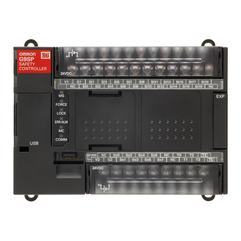
Removable terminal (I/O)
Removable terminal (Power,I/O)
Node Address
Switch
Baud Rate
Switch
USB Port
DeviceNet
Connector
Input LED
Output LED
131.4135.6
(114.1)
(99)
111.1
Indicates a potentially hazardous situation which, if not avoided, will
result in minor or moderate injury, or may result in serious injury or
death. Additionally there may be significant property damage.
Indicates prohibited actions
Indicates mandatory actions
EU Declaration of Conformity
Standards
WARNING
RequirementsControlling Devices
Use approved devices with Direct Opening Mechanism complying with
IEC/EN 60947-5-1.
Emergency stop
switch
Use approved devices with Direct Opening Mechanism complying with
IEC/EN 60947-5-1 and capable of switching micro loads of 24VDC, 4mA.
Door interlocking
switch
Limit switch
Use approved devices with forcibly guided contacts complying with
IEC61810-3.
For feedback purpose, use devices with contacts capable of switching
micro loads of 24VDC, 4mA.
Relay with forcibly
guided contacts
Use contactors with forcibly guided mechanism and monitor its auxiliary
NC contact to detect failures of contactor.
For feedback purpose, use devices with contacts capable of switching
micro loads of 24VDC, 4mA.
Contactor
Use approved sensors complying with the relevant product standards,
regulations, and rules in the country where it is used.
Safety sensor
Evaluate whether devices used are appropriate to satisfy the requirements
of safety category level.
Other devices
Serious injury may possibly occur due to loss of required safety functions. Do not use
DeviceNet standard I/O data or Explicit message data as any safety data.
Serious injury may possibly occur due to loss of required safety functions. Do not use
LEDs on the NE1A-SCPU02 for safety operations.
Serious injury may possibly occur due to loss of required safety functions. Do not use
test outputs of the NE1A-SCPU02 as any safety outputs.
The following alert symbols are used in this manual.
Serious injury may possibly occur due to breakdown of outputs. Do not connect loads
beyond the rated value to the safety outputs and the test outputs.
Serious injury may possibly occur due to loss of required safety functions.Ground the
0V line of the power supply for external output devices so that the devices do Not
turn ON when the safety output line or the test output line is grounded.
Serious injury may possibly occur due to loss of required safety functions. Use
appropriate components or devices according to the requirements given in the
following table.
Serious injury may possibly occur due to loss of required safety functions.Wire the
NE1A-SCPU02 properly so that 24VDC line do NOT touch the outputs accidentally or
unintentionally.
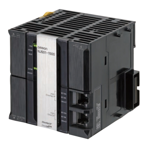
Thank you for purchasing this NE1A-SCPU02.
This manual primarily describes precautions required in installing and operating the
NE1A-SCPU02.
• Only qualified person trained in professional electrical technique should be handle the
NE1A.
• Before operating the NE1A-SCPU02, read this manual through to acquire sufficient
knowledge of the NE1A-SCPU02.
• To ensure safe and correct use of the NE1A-SCPU02, also read the following manuals:
• Safety Network Controller OPERATION MANUAL(Cat.No.Z906-E1)
• SYSTEM CONFIGURATION MANUAL(Cat.No.Z905-E1)
• DeviceNet™ OPERATION MANUAL (Cat. No. W267-E1)
• Keep this manual for future reference.
INSTRUCTION MANUAL
Alert Statements
Meaning of Alert Symbols
WARNING
TYPE NE1A-SCPU02
Safety Network Controller
Original instructions
NE1A-SCPU02 is designed and manufactured in accordance with the following standards:
EN ISO13849-1:2015 Cat.4 PL e EN62061
IEC61326-3-1 EN60204-1
EN ISO13850 NFPA 79
IEC61508 parts 1-7 SIL3 ANSI RIA 15.06
EN61131-2 ANSI B11.19
UL508 CSA C22.2 No.142, No.213
ANSI/ISA 12.12.01 ANSI/UL1998
EN ISO13849-2
• The maximum terminal temperature is 80 °C
• Use SELV Power Source for the DC main power source.
English
OMRON declares that NE1A-SCPU02 is in conformity with the requirements of the following EU
Directives:
EMC Directive:2014/30/EU Machinary Directive:2006/42/EC
Instructions in the official EU languages and a signed EU Declaration of Conformity in
English are available on our website at http://www.ia.omron.com/support/models/.
In case that a safety output is configured as “Safety Pulse Test”, while this output is in an ON state, the pulsed
off signal(pulse width:580µs) is output continuously for fault diagnosis. Confirm response time of device
connected to safety outputs so the device does not malfunction due to this off pulse.
2) T0-T7 total current at the same time:1.4A
1) V0-G0: for internal logic circuit, V1-G: for external input devices and test outputs
V2-G: for external output devices
Item Specifications
DeviceNet supply voltage 11 to 25VDC (Supplied from communications power supply)
Current consumption V0 (internal logic circuit) 280mA at 24VDC
DeviceNet current consumption 15mA at 24VDC
Device supply voltage V0, V1, V2 1) 20.4 to 26.4VDC (24VDC, -15% to +10%)
EMC Conform to IEC61131-2
Operating Temperature -10 to +55deg.C
Storage Temperature -40 to +70deg.C
Relative Humidity 10 to 95% non-condensing
Vibration resistance 0.35 mm at 10 to 57Hz, 50m/s2at 57 to 150Hz
Shock resistance 150m/s2: 11ms
Over Voltage Category II (per IEC61131-2: 4.4.2)
Weight 690g
Protection degree IP20
1. SPECIFICATIONS
Specifications
Current sinking
11VDC min.
5VDC max.
1mA max.
4.5mA
Do not drop the NE1A-SCPU02 to the ground or excessive vibration or mechanical shocks. The NE1A-SCPU02
may be damaged and may not function properly.
Precautions for Safe Use
• Use the NE1A-SCPU02 within an enclosure with IP54 protection or higher of IEC/EN 60529.
• Use DIN rail (TH35-7.5 according to IEC60715) for placing the NE1A-SCPU02 into the control board.
• Mount the NE1A-SCPU02 to DIN rails with attachments (TYPE PFP-M, not incorporated to this product), not to
drop out of rails by vibration etc.
• Spacing should be available around the NE1A-SCPU02 at least 50mm from its top and bottom surfaces for
ventilation and wiring.
• This is a class A product. In residential areas it may cause radio interference, in which case the user may be
required to take adequate measures to reduce interference.
• Use the following to wire external I/O devices to the NE1A-SCPU02.
• Disconnect the NE1A-SCPU02 from power supply when wiring. Devices connected to NE1A-SCPU02 may
operate unexpectedly.
• Apply properly specified voltages to the NE1A-SCPU02 inputs. Applying inappropriate DC voltage and any AC
voltages cause the NE1A-SCPU02 to fail.
• Be sure to separate the communication cable and the I/O cable from the high-voltage/current lines.
• Be cautious not to have your fingers caught when attaching connectors to the plugs on the NE1A-SCPU02.
• Mount screw of DeviceNet Connector and I/O Connector correctly. (0.25-0.3N•m)
• Incorrect wiring may lead to loss of safety function. Wire conductors correctly and verify the operation of the
NE1A-SCPU02 before commissioning the system in which NE1A-SCPU02 is incorporated.
• After wiring is completed, be sure to remove label for wire clipping prevention on the NE1A-SCPU02 to enable
heat to escape for proper cooling.
• Disconnect the NE1A-SCPU02 from power supply when replacing. Devices connected to the NE1A-SCPU02 may
operate unexpectedly.
• Do not dismantle, repair, or modify the NE1A-SCPU02. It may lead to loss of its safety functions.
Use DC power supply satisfying requirements below.
• Secondary circuits of DC power supply is isolated from its primary circuit by double insulations or reinforced
insulations.
• DC power supply satisfies the requirement for class 2 circuits or limited voltage/current circuit stated in UL 508.
• 20ms or over of the output hold time.
• DC power supply that satisfies the requirements for SELV given in IEC/EN60950-1 or EN 50178.
Solid wire
Standard (Flexible) wire
0.2 to 2.5mm2AWG24 to 12
0.34 to 1.5mm2 AWG22 to 16
Do not use or store the NE1A-SCPU02 in any of the following locations.
• Locations subject to direct sunlight.
• Locations subject to temperatures or humidity outside the range specified in the specifications.
• Locations subject to condensation as the result of severe changes in temperature.
• Locations subject to corrosive or flammable gases.
• Locations subject to dust (especially iron dust) or salts.
• Locations subject to water, oil, or chemicals.
• Locations subject to shock or vibration.
Take appropriate and sufficient countermeasures when installing systems in the following locations. Inappropriate
and insufficient measures may result in malfunction.
• Locations subject to static electricity or other forms of noise.
• Locations subject to strong electromagnetic fields.
• Locations subject to possible exposure to radioactivity.
• Locations close to power supplies.
• Be cautious not to have you injured when dismantling the NE1A-SCPU02.
The above-mentioned is a part of directions. Please use it after reading the operation manual.
Handle with care
Installation and storage environment
Installation/ Mounting
Installation/ Wiring
Power Supply Selection
Periodical Inspection and Maintenance
Disposal
Environmental Specifications
Item
Inputs type
ON voltage
OFF voltage
OFF current
Input current
Specifications
Current sourcing
0.7A max. / channel 2)
1.2V max.
0.1mA max.
Item
Outputs type
Rated output current
Residual voltage
Leakage current
Safety Input Specifications
Specifications
Current sourcing
0.5A / channel
1.2V max.
0.1mA max.
Item
Outputs type
Rated output current
Residual voltage
Leakage current
Safety Output Specifications
Test Output Specifications
•
Node Address is settable by 2 digit 10-position Rotary Switch.
•
Node Address range is from 0 to 63.(Default:63)
•
If set from 64 to 99,Node Address is settable by Configuration tool.
X : Don't care
0
1
2
3
4
5
6
7
8
9
0
1
2
3
4
5
6
7
8
9
x10
x1
1
2
O
N
3
4
ON
• At normal state, 7-Segment LED displays the node address of the NE1A-SCPU02 itself in decimal number
(00-63). The node address, depending on the operational state of the NE1A-SCPU02, turns “ON” or “Flashing”.
• If in fault status, error code and error occurrence node address are displayed alternately in the order of node
address.
• In “standalone mode”, “nd” is displayed in the normal condition.
(Unit:mm)
LED Designations
MS
(Module Status)
NS
(Network Status)
LOCK
(Configuration
Lock)
COMM
(USB)
IN 0, 1, 2 • • • 39
OUT 0, 1,2 • • • 7
(I/O status)
In Executing
In Idle
In Critical fault
In Recoverable fault
In Self Testing, Waiting for TUNID, or Configuring
LED Color
Green/Red
Green
Red
Failure detected in the Input / Output circuit Discrepancy
error has occurred in I/O set for dual channel mode
Failure detected in the associated I/O circuit in case of
dual channel configuration
Indicators
7 segment LEDs
Rotary Switch
Dip Switch
Terminal Designations and functions
Status
Lit
Flashing
Lit
Flashing
Online connection established
Online but connection not established
Critical link failure
Connection time-out
Green
Red
Red
Yellow
Lit
Flashing
Lit
Flashing
Flashing
No power
-
Not lit
Not online / Not powered
-
Not lit
In Waiting for TUNIDGreen/Red Flashing
Locked Valid Configuration
Unlocked Valid Configuration
Lit
Flashing
Invalid ConfigurationNot lit
CommunicatingFlashing
Not communicatingNot lit
Yellow
Yellow
-
Input / Output signal ONLit
Lit
Input / Output signal OFFNot lit
Flashing
Description
3. INTERNAL CIRCUITRY AND WIRING
Test output terminal for use in conjunction with IN0 through IN19 safety
inputs. Each test output provides a unique set of test pulse patterns. T3 also
supports current monitoring of the output signal for e.g. muting applications.
Descriptions
Power terminal for external input devices and test outputs.
Power terminal for external input devices and test outputs.
Power terminal for external output devices e.g. safety outputs.
Power terminal for external output devices e.g. safety outputs.
Terminal for Safety input signals.
Power terminal for internal circuit (Logic).
Power terminal for internal circuit (Logic).
Terminal
Designations
V0
G0
V1
G
V2
G
IN0 through IN39
Terminal for Safety outputs
OUT0 through OUT7
T0 through T3
Test output terminal for use in conjunction with IN20 through IN39 safety
inputs. Each test output provides a unique set of test pulse patterns. T7 also
supports current monitoring of the output signal for e.g. muting applications.
T4 through T7
2. PART NAMES AND FUNCTION / DIMENSIONS
Baud Rate
125Kbit/s (default)
250Kbit/s
500Kbit/s
Auto Baud Rate Detection
Software setting
1234
Switch
OFF
OFF
OFF
OFF
OFF
OFF
OFFOFF
OFF
OFF OFF
OFF
OFFOFF
OFF
OFF
OFF
OFF
OFF
ON
ON
ON
ON
ON
ON
ON
ON
ON
ON
ONON
ON
1
XXX
V+
CAN H
Drain
CAN L
V-
Color Description
Red V+
White Signal(CAN H)
Drain
Blue
Signal(CAN L)
Black V-
DeviceNet Connector
Internal Circuitry and wiring example
I/O Wiring example: Emergency Stop (dual channel) with manual reset
Omron Companies shall not be responsible for conformity with any standards, codes
or regulations which apply to the combination of the Product in the Buyer’s application
or use of the Product. At Buyer’s request, Omron will provide applicable third party
certification documents identifying ratings and limitations of use which apply to the
Product. This information by itself is not sufficient for a complete determination of the
suitability of the Product in combination with the end product, machine, system, or
other application or use. Buyer shall be solely responsible for determining
appropriateness of the particular Product with respect to Buyer’s application, product
or system. Buyer shall take application responsibility in all cases.
NEVER USE THE PRODUCT FOR AN APPLICATION INVOLVING SERIOUS RISK
TO LIFE OR PROPERTY OR IN LARGE QUANTITIES WITHOUT ENSURING THAT
THE SYSTEM AS A WHOLE HAS BEEN DESIGNED TO ADDRESS THE RISKS,
AND THAT THE OMRON PRODUCT(S) IS PROPERLY RATED AND INSTALLED
FOR THE INTENDED USE WITHIN THE OVERALL EQUIPMENT OR SYSTEM.
Suitability for Use
Additional Precautions According to ANSI/ISA 12.12.01
1. This equipment is suitable for use in Class I, Div.2, Group A, B, C, D or Non-Hazardous Locations Only.
2. WARNING: Explosion Hazard-Substitution of Components may Impair Suitability for Class I, Div.2.
3. WARNING: Explosion Hazard. Do not Disconnect Equipment Unless Power Has Been Switched off or the Area Is
Known to Be Non-Hazardous.
4. This device is open-type and is required to be installed in an enclosure suitable for the environment and can only be
accessed with the use of a tool or key.
5. WARNING: Explosion Hazard - Do not connect USB Connector Unless Power Has Been Switched Off Or The Area
Is Known To Be Non-Hazardous.
1. Cet equipement convient a l'utilisation dans des emplacements de Classe I, Division 2, Groupes A, B, C, D, ou ne
convient qu'a l'utilisation dans des endroits non dangereux.
2. AVERTISSEMENT - Risque d'explosion - La substitution de composants peut rendre ce materiel inacceptable pour
les emplacements de Classe I, Division 2
3. AVERTISSEMENT - Risque d'explosion - Avant de debrancher l'equipement, couper le courant ou s'assurer que
l'emplacement est designe non dangereux.
4. Ce dispositif est de type ouvert et doit etre installe dans un coffret adapte a l'environnement et auquel on ne pourra
acceder uniquement au moyen d'un outil ou d'une cle.
5. AVERTISSEMENT - Risque d'explosion - Ne pas déconnecter l'USB avant que l'alimentation ait été coupée ou que
la zone soit reconnue comme non dangereuse.
Altitude Max. 2000m
Pollution Degree 2
11
12
21
22
S1
KM2
KM1
M1
Regional Headquarters
OMRON EUROPE B.V. (Importer in EU)
Note: Specifications subject to change without notice.
Wegalaan 67-69,2132 JD Hoofddorp
The Netherlands
Tel: (31)2356-81-300
Fax: (31)2356-81-388
OMRON ASIA PACIFIC PTE. LTD.
No. 438A Alexandra Road #05-05/08
(Lobby 2), Alexandra Technopark,
Singapore 119967
Tel: (65) 6835-3011
Fax: (65) 6835-2711
OMRON ELECTRONICS LLC
2895 Greenspoint Parkway, Suite 200
Hoffman Estates, IL 60169 U.S.A.
Tel: (1) 847-843-7900
Fax: (1) 847-843-7787
OMRON (CHINA) CO., LTD.
Room 2211, Bank of China Tower,
200 Yin Cheng Zhong Road,
Pu Dong New Area, Shanghai,
200120, China
Tel: (86) 21-5037-2222
Fax: (86) 21-5037-2200
OMRON Corporation (Manufacturer)
Shiokoji Horikawa, Shimogyo-ku, Kyoto, 600-8530 JAPAN
Contact: www.ia.omron.com
© OMRON Corporation 2006-2021 All Rights Reserved.
0631730-2 I
