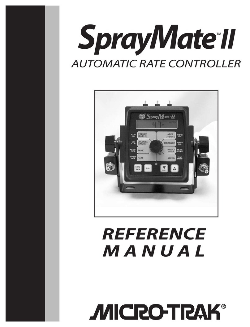
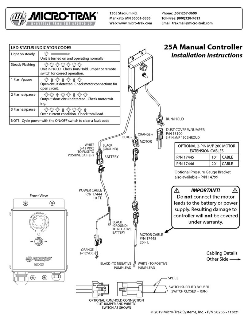
micro-trak SprayMate Plus User guide


2
111 LeRay Avenue
Eagle Lake, MN 56024-9650
© 2021 • Micro-Trak® Systems, Inc.
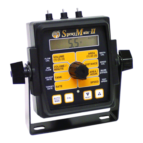
The SprayMate TM Plus console is an enhanced version of the SprayMateTM II. The SprayMate TM Plus adds features to broaden
the usage in the vegetable (fumigant) markets. The SprayMate TM Plus is an electronic control system that can help you
achieve maximum yields and operate more cost-effectively by providing the information you need to maintain proper
application rates of liquid chemicals and fertilizer. SprayMateTM Plus has been designed for easy installation and operation.
However, since each installation will vary depending on your equipment, please take time to familiarize yourself with this
manual and the actual components before beginning. Following the procedures described in this manual will ensure proper
performance and help avoid problems or questions once you are in the field.
This manual is written for the SprayMate TM Plus, which may be used for either English, Metric or Turf measurement. Please
read the manual carefully and follow the instructions as they apply to your usage.
If you do encounter a problem that cannot be corrected by reviewing this manual, consult your dealer or distributor, or
contact a Micro-Trak® technician for assistance.
U.S. or Canada: Toll-free (800) 328-9613 or (507) 257-3600
Fax: 507-257-3001
System Manual
SprayMate™ Plus
Auto Rate Controller

3
Micro-Trak Systems, Inc.
Limited Warranty Statement
Micro-Trak Systems, Inc. (herein “Seller”) warrants to the original purchaser (herein “Buyer”) that, if any product or part of the prod-
uct (herein “Parts”) proves to be defective in material or workmanship, upon inspection and examination by Seller, within three (3)
years from the original date-of-purchase, and is returned to Seller with dated proof-of-purchase, transportation prepaid, within
sixty (60) days after such defect is discovered, Seller will, at their option and sole discretion, either repair or replace said part, except
that the warranty for expendable Parts, including but not limited to, light bulbs, batteries, hose and tubing, nuts, bolts, screws and
other fasteners shall be thirty (30) days from the original date-of-purchase; and except that the warranty for Parts manufactured by
someone other than the Seller, including but not limited to, shut-o valves, control (servo) valves, owmeters, pressure sensors and
regulators, pumps, motors, compressors, tanks and tank accessories, DGPS receivers and related repeater and base stations shall be
one (1) year from the original date-of-purchase; and except that the warranty for Parts manufactured by someone other than the
Seller, including but not limited to, memory cards and drives, mapping software, terminals, PC’s, laptops, tablets and other com-
puter devices shall be thirty (30) days from the original date-of-purchase. Any damage or failure to said part resulting from abuse,
misuse, neglect, accidental or improper installation or maintenance, unauthorized modication, use with other parts and/or prod-
ucts, or attributable to acts of God, as determined solely by the Seller, will invalidate the warranty. Said part will not be considered
defective if it substantially fullls the performance specication. Buyer shall be responsible for all maintenance services, if any, all in
strict accordance with the procedures outlined in the manual. The warranty does not include labor, installation, replacement parts
or repairs, delivery of replacement parts or repairs or time and travel. Said warranty is non-transferable.
THE FOREGOING WARRANTY IS EXCLUSIVE AND IN LIEU OF ALL OTHER WARRANTIES OF MERCHANTABILITY, FITNESS FOR PURPOSE
AND OF ANY OTHER TYPE, WHETHER EXPRESS OR IMPLIED. THE SELLER’S LIABILITY, WHETHER IN CONTRACT, IN TORT, UNDER
ANY WARRANTY, IN NEGLIGENCE OR OTHERWISE, SHALL NOT EXCEED THE RETURN OF THE AMOUNT OF THE PURCHASE PRICE
PAID BY THE BUYER, AND UNDER NO CIRCUMSTANCES SHALL THE SELLER BE LIABLE FOR SPECIAL, INDIRECT, CONSEQUENTIAL,
INCIDENTAL OR PUNITIVE DAMAGES. SELLER NEITHER ASSUMES NOR AUTHORIZES ANYONE TO ASSUME FOR IT ANY OTHER
OBLIGATION OR LIABILITY IN CONNECTION WITH SAID PART. NO ACTION, REGARDLESS OF FORM, ARISING OUT OF THE TRANS
ACTIONS UNDER THIS AGREEMENT MAY BE BROUGHT MORE THAN ONE 1YEAR AFTER THE CAUSE OF ACTION HAS OCCURRED.
Buyer accepts these warranty terms and limitations unless the part is returned to Seller, via proper distribution channels and ap-
proved return authorization, with dated proof-of-purchase, transportation prepaid, within sixty (60) days from the date-of-purchase
for refund of the purchase price.
Source Doc: MTS Warranty Statement 080120
At Micro-Trak® Systems, we believe a product that delivers quality and performance at a reasonable cost is what is needed to help
today’s operator and the operator of the future compete in the world market.
It is our goal to provide operators with a line of electronic equipment that will help build and maintain an efficient and profitable
operation that can be passed on to future generations.
We thank you for your purchase and hope that we can be of service to you in the future.
Micro-Trak® Systems, Inc.
MAIL and UPS:
Micro-Trak® Systems, Inc.
ATTN: Service Department
111 LeRay Avenue
Eagle Lake, MN 56024-9650
4
Table of Contents
Micro-Trak®Warranty 3
Table of Contents 4
Component Parts and Hardware 5
System Overview 6
Wiring Diagram 7
Installation 8
Overview 8
Installation Steps 8
Mounting the Console 9
Electrical Installation 10
Branch Harness Connections 11
Speed Sensor Options 12
Optional Equipment - Switches 13
Plumbing Overview - Bypass 14
Plumbing Overview - Inline 15
System Components 16
Feature Summary 18
SprayMateTM Plus Console Function Summary 20
Calibration 21
Calibration Steps: 21
Restoring Default Calibration Values 21
Calibration Positions 22
Special Calibration 23
Operation 29
Manual Operation 29
Automatic Operation 29
Care and Maintenance of your SprayMate™ Plus 29
Console Controls 30
Additional System Features 31
Pre-Field System Checkout 32
Troubleshooting 33
Messages/Warnings 33
General 34
Checking Individual Components 35
Checking Console Inputs 36
Plumbing Troubleshooting Chart 37
Plumbing Guidelines 37
Appendices 38
A - Remote Run/Hold Kit Installation 39
B - Magnetic Speed Sensor Installation 40
C - Fine Tuning Speed/Distance Calibration Value 43
D - Fine Tuning Flowmeter Calibration Value 44
E - “Quick Start” Function 45
F - NH3 Control 46
G - “Open Loop”Control & Closed Loop Override 58
H - Pulse Width Modulation (PWM) Live Calibrate 59
I - Pressure Based Control 63
J - Default Calibration Values 64
K - Radar Adapter Cables 65
L - Conversion Chart 66
M - Replacement Parts List 67
N - Electric Motor Driver - Setup & Connectivity 68

5
Component Parts and Hardware
Branch Harness
w/Weather Pack Tower Conn.
P/N 18532
Console Mount Kit
P/N 13181
SprayMateTM Plus Console
P/N 18700
(2)
(2)
(2)
(2)
(2)
(2)
(2)
Power Cable
P/N 14315
14” Nylon cable ties (10)
P/N 12910
120” 10-pin Extension Cable
P/N 14316
Reference Manual
P/N 18770
Run/Hold Switch Kit
P/N 21778
Power Switch Kit
P/N 21779
AUTO

6
System Overview
15’
10’
10-PIN M/P
10’
18”
M/P
W/P
M/P
W/P
W/P
W/P
W/P
Note: Branch Harness diagram shown is P/N
18532 w/Weather Pack Tower connectors. The
P/N 18280 cable w/ Weather Pack Shroud con-
nectors has the same layout.

7
Wiring Diagram
*
*
Note: Branch Harness shown is P/N 18532
w/Weather Pack Tower connectors. The P/N
18280 cable w/ Weather Pack Shroud connec-
tors has the same wiring layout.

8
Installation
Overview
Install the SprayMate™Plus console and system components by following the recommended sequence
of steps. Your installation may not include some of these steps; some equipment is optional and some
components may already be installed. All installations must follow Calibration and Pre-Field System
Checkout steps (9,10) to ensure safe and accurate operation of system.
Installation Steps
1. Mount the Console, Power Switch, and Run/Hold Switch.
See page 9.
2. Route wiring to appropriate locations on vehicle and/or implements.
See page 10.
3. Connect wiring harness to 12VDC power.
See page 10.
4. Connect wiring harness to Section Shutoff valves.
See page 10.
5. Mount Speed Sensor and connect to system.
See page 12.
6. (Optional) Mount Implement Switch and connect to system.
See page 13.
7. Mount Flowmeter and join to system.
See page 16.
8. (Optional) Mount Pressure Sensor and connect to system.
See page 16.
9. Calibrate SprayMate™ Plus system.
See page 21.
10. Perform Pre-Field System Checkout Procedure.
See page 32.

9
Installation (cont.)
Mounting the Console
Figure 1
Figure 2
Mount Knob
Carriage Bolts
Rubber Washer
Rubber Washer
Mount Knob
Switch Bracket
Switch Bracket
Select a mounting location which seems most workable, and best fits
your needs. It should be convenient to reach and highly visible to
the operator. DO NOT INSTALL IN A POSITION THAT OBSTRUCTS
THE VIEW OF THE ROAD OR WORK AREA. Whenever possible, avoid
locations that expose the console to direct sunlight, high temperature,
strong chemicals or rain.
Place the mounting bracket in the selected location, mark holes, drill
¼” (7mm) holes and mount bracket with bolts, lock washers and nuts
provided. (Use self-tapping screws if not practical to use bolts.)
See Figure 1.
Put rubber washers on carriage bolts and put the bolts through the
bracket holes from the inside out. Slide console over carriage bolt heads.
Install the switch brackets over the carriage bolts and alongside the
console bracket. Install the mount knobs on the carriage bolts and
tighten to secure the console and switch brackets in place. See Figure 2.
Mount the switches in the brackets then join the switch harness
connectors to the mating connectors on the console harness. Typically
the power On/Off switch (Kit 21779) is mounted on the left and the Run/
Hold switch (Kit 21778) is mounted on the right. See Figure 3.
Drill ¼” (7mm)
holes for bolts,
or 3/16“ (5mm)
holes for self-
tapping screws.
Bolts
Lockwashers
and nuts
Figure 3

10
Installation (cont.)
Electrical Installation
This section explains how to hook-up your SprayMateTM Plus to a 12VDC power connection and On/Off Switch, and wiring
information about section shut-off valves connections.
The SprayMateTM Plus must be connected to a 12VDC negative ground electrical system.
ROUTING HARNESS AND CABLING
Avoid areas where the cable may be subjected to abrasion or excessive heat.
SECTION SHUTOFF VALVES
The SprayMateTM Plus branch harness includes connections for 3 section valves. The wiring to each Weather Pack connector
consists of +12VDC, Ground, and switched +12VDC. See Figure 5. For solenoid type valves, use connections Band Conly.
Verify the wiring layout of your valves before connecting them to the SprayMateTM Plus. Please refer to original valve
documentation or contact valve manufacturer if you are unsure of the correct wiring configuration.
+12 VDC
15A in-line fuse
(+)
(–)
Ground
(Black)
(Red)
(Orange)
A
B
C
WHT/RED
WHT/BLK
Constant +12VDC
Switched +12VDC (Signal)
Ground
Color of wire
varies by section
3-Pin
Weather Pack
Tower/Shroud
Connector
Figure 4 - Power/Battery Connection
Figure 5 - Example Section Valve Connection
POWER/BATTERY CONNECTION
Locate the power cable lead on the SprayMateTM Plus harness and route to the battery Attach the BLUE wire to ground. See
Figure 4. Be sure there is a good metal-to-metal contact. Connect the ORANGE wire to the positive battery terminal.
Connect the power to the SprayMateTM Plus console by plugging the 2-pin W/P tower on the power cable into the 2-pin W/P
shroud connected to the display console.
WIRING HARNESS ORIENTATION
Wiring with multiple branches must be installed so that the individual wires point downward, as shown. This will protect the
internal connections from exposure to liquid chemicals.
WRONG RIGHT

11
Installation (cont.)
Branch Harness Connections
Section 1
ON/OFF
Section 2
ON/OFF
Section 3
ON/OFF
FLOW
CONTROL
MULTIFUNCTION
RUN/HOLD
+12V
SIGNAL OUT
GND
+12V
GND
+12V
GND
SIGNAL OUT
SIGNAL OUT
SIGNAL IN
GND
CONTROL
–
OUT
CONTROL
+
OUT
+12V
SIGNAL IN
SIGNAL OUT
GND
GND
+12V
+12V
Note: Branch Harness shown is
P/N 18532 w/Weather Pack Tower
connectors. The P/N 18280 cable w/
Weather Pack Shroud connectors
has the same wiring layout.

12
Installation (cont.)
Speed Sensor Options
The SprayMateTM Plus must be connected to a speed sensor to utilize its calculating function.
Several possible options are listed below:
ASTRO SERIES OR OTHER GPS SPEED SENSOR INTERFACES
The SprayMate Plus is designed to easily connect to the Micro-Trak Astro series speed sensor. It also may be used with most
GPS speed sensors that output a pulsed signal, such as the Squibb-Taylor®SkyTrak or Dickey-John®GPS speed sensors. An
adapter cable may be required.
MAGNETIC WHEEL SENSOR
This system uses magnets attached to a wheel hub or drive shaft and a hall-effect sensor. The movement of the magnets near
the sensor creates an electrical pulse which the console uses as a speed input. The system must be carefully calibrated to
ensure accurate readings. SEE APPENDIX B FOR MAGNETIC SENSOR INSTALLATION.
VANSCO™RADAR SPEED SENSOR AVAILABLE FROM MICROTRAK DEALERS & DISTRIBUTORS
The Vansco radar speed sensor uses a microwave (radar) signal to deliver a reliable, accurate speed signal for electronic
equipment. It features state-of-the-art electronic design/manufacturing, rugged aluminum housing and complete testing and
certification.
RADAR INTERFACE
The SprayMateTM Plus may also be interfaced with most popular radar ground speed sensors. An adapter cable is required for
proper interface.
SEE Appendix K FOR LIST OF ADAPTER CABLES FOR RADAR.
ASTRO SERIES GPS SPEED SENSOR INSTALLATION:
RECEIVER: The GPS receiver may be mounted either externally (roof of the cab or other place
with a clear view of the sky) or inside the vehicle cab. However, if mounted inside the cab there
may be some loss of accuracy due to blockage of satellite signals. For most reliable operation,
mount the GPS receiver in a location where it has an unobstructed view of the sky. Mount the
receiver using the integral magnet or the included self-adhesive fastener tape. If using the
fastener tape - clean the mounting location, remove the plastic backing, and press firmly to the
surface.
WIRING: Route the 10 foot cable from the receiver into the cab (if receiver is externally
mounted). Avoid sharp edges or heat sources. The rectangular module is roughly the same size
as the connector and will fit through the same opening.
MODULE: The small potted module includes a power LED and a GPS status LED. The module can be mounted in a visible
location using the included self-adhesive fastener tape, or placed out of sight.
• Power LED (closest to connector) : On when 12VDC is connected
• GPS Status LED (closest to receiver): Flashes when the GPS receiver is active and scanning for a satellite. When a signal is found, it will
remain on. If the GPS system fails, the light will turn off.
CONSOLE CONNECTION: Connect the short cable from the Astro to the 3-pin connector labeled SPEED on your console.
Proximity Sensor
Micro-Trak® also offers a proximity sensor - P/N 01554 Gear tooth sensor kit. It is useful in situations where it is impractical or
inadvisable to use a flowmeter to monitor flow of material. It can also serve as a Speed sensor. The 01554 Gear tooth sensor
responds to the close presence of ferrous metals and sends a signal to the console via the Flow or Speed connection. The
recommended air gap between sensor and moving part is 1/16” (tip: use a U.S. dime as a gauge). To calibrate the system to use
this sensor for Flow, use the Appendix
D - Fine Tuning Flowmeter Calibration, for Speed, use Appendix C - Fine Tuning Speed/
Distance. For use as a Flow monitor for PWM systems, use Appendix G - Closed Loop Live
Calibration for PWM control.

13
Installation (cont.)
Optional Equipment - Switches
Contact a Micro-Trak® dealer or distributor for more information on these accessories.
A Dealer Locator can be found online at http://www.micro-trak.com/where-to-buy/dealer-locator.
Micro-Trak offers two options for automatically controlling the operation of the SprayMate Plus system. Both solutions
mount directly to your implement and control run/hold as the machine is operated. Installation locations vary by the type of
machinery used. Both types of Implement Switch join to the “Run/Hold” connection on the Branch Harness.
Whisker Switch Assy.- P/N 18541
Simply mount the Whisker Switch Assembly near a moving part of an operating mechanism on your implement (additional
extension cables may be needed). The connector labelled “SafeGuard Run/Hold” is wired Normally Open. The default polarity
for the SprayMate Plus Run/Hold circuit is preset to “Closed”, meaning pressure on the switch tip causes the system to “Hold”.
See figure 6. The polarity setting can be accessed in Special Calibration settings (see page 23) - it is called “Hold Input Polarity”.
Magnetic Base Coil Spring
3-pin Metri Pack
Connector
3-pin Metri Pack
Connector
Remote Run/Hold Sensor Kit- P/N 01535
The Remote Run/Hold Sensor consists of a Hall-effect proximity sensor and a magnet. Mount the sensor near a moving part
of an operating mechanism on your implement; mount the magnet on the moving part (additional extension cables may be
needed). The sensor is wired Normally Open; the default polarity for the SprayMate Plus Run/Hold circuit is preset to “Run”.
Moving the magnet close to the sensor tip causes the system to “Hold”. See figure 7. The polarity setting can be accessed
in Special Calibration settings (see page 25) - it is called “Hold Input Polarity”. More extensive instructions on installing the
Remote Run/Hold Sensor can be found in Appendix A.
3-pin Metri Pack Connector
Hall-eect sensor
Magnet
Figure 6
Figure 7

14
Installation (cont.)
SprayMateTM Plus Plumbing Overview
Bypass Configuration - Flow through servo bypasses flowmeter
*ITEMS NOT INCLUDED
WITH SYSTEM

15
Installation (cont.)
SprayMateTM Plus Plumbing Overview
In-Line Configuration - Flow through servo is inline with flowmeter

16
Installing Flowmeter
The flowmeter must be installed in the main line after any
strainers, return lines, or valves. Securely mount flowmeter
in an area away from intense vibration. A vertical installation
with flow entering the bottom is preferred, especially at rates
below 5 gallons per minute. See figure 8. Other orientations
are sufficient providing the flowmeter remains full of fluid. To
avoid erratic flow readings allow a minimum of 6” of straight
tubing at the flowmeter input and output. If installation
constraints don’t allow this keep bends as gentle as possible.
Micro-Trak® flow meters are bidirectional (exception: green
plastic turbine and mag flowmeters are one direction only).
Flipping the flowmeter periodically (black nylon and stainless
steel Micro-Trak® manufactured models) to reverse the flow
will greatly extend the life of the flowmeter by evening out
bearing wear.
Installing Flow Sensor Cable
The flow sensor cable has a GREEN sensor body and joins the
3-pin connector on the wiring harness marked FLOW. See
figures 9 and 10.
1. Screw threaded sensor into hole of flowmeter until seated.
2. Gently tighten 3/8” jam nut to secure sensor in place.
3. Uncoil flow sensor cable and route it to wiring harness.
4. Align connectors and press firmly together until locking tab
clicks into place.
5. Secure cable with plastic ties provided.
See SprayMate™ Plus Wiring Diagram on page 7.
NOTE: Sensors with GREEN bodies can be used for either
SPEED or FLOW but not for REMOTE RUN/HOLD.
A B C
C B A
Flow Sensor
Cable Connector
Main Harness
Flow Connector
FLOW
Figure 9
Figure 10
Figure 11
Installation (cont.)
System Components
Sprayer Line*
Locknut
Sensor
(green body)
Flowmeter
* NOT SUPPLIED
“L” Bracket*
Hose Clamps*
¾” NPT Male Fitting*
Hose Clamps*
Hose Clamps*
5’ Hall-eect Flow Sensor Cable
with Threaded Sensor ConnectorGreen Body
Figure 8
Care and Maintenance
At end of application season, thoroughly flush Flowmeter with clean water, and drain completely
.
• The input pressure on the glass-filled nylon flowmeter FM750 GFN should not exceed 100 PSI (689 kpa).
• Do not expose the flowmeter to liquid temperatures exceeding 130 degrees F (55 degrees C).
• Some chemicals may damage the turbine material - Noryl GTX. If you are in doubt, contact the chemical manufacturer.
P/N 18757 - 150 PSI
P/N 18758 - 300 PSI
Installing Pressure Sensor (Optional)
The pressure sensor should be installed in the main line of flow as
close to the section shut-off valves as possible. The sensor requires a
1/4” - 18 NPT fitting. See figure 11.
1. Install the sensor in the plumbing line.
2. Join the cable to the 3-pin Packard™ connector on the sensor.
3. Route the cable (and extension cables, if needed) to the console
location - avoid sharp surfaces and heat sources.
4. Join the cable to the PRESSURE connection on the wiring
harness - align connectors and press firmly together until locking
tab clicks into place.

17
Servo, Throttling Valves
For BYPASS installations, the servo valve installs in an
unrestricted return line to the inlet of the pump or directly
into the tank. The console must be calibrated for bypass
operation, see Calibration section. DO NOT install the
servo valve closer than 12” to the flowmeter. The servo
valve has a flow direction decal on it. Make certain that
the actual flow direction matches the decal on the servo
valve. DO NOT install the servo valve in the agitation line.
Slow response time and marginal operation may result.
The return line should tee from the main line just after the
throttling valve. See Figure 14. The throttling valve is used
to limit the output (set maximum output) of the pump
to the flowmeter and servo valve. The throttling valve is
adjusted to put the servo valve in its optimal operating
range. Please refer to Pre-Field System Checkout on page
32 for proper valve adjustment procedure.
The servo valve connects directly to the 3-pin connector
on the main harness. If more length is required, use a 3-pin
W/P extension cable of the appropriate length.
NOTE: For Inline operation, the servo valve is installed in the
main spray line as shown in Figure 15.
Figure 14
Servo Valve
Cable
From Pump
Throttling
Valve
To Flowmeter
Servo Valve
Return to pump
inlet or unrestricted
return to tank.
Bypass
Servo
Flowmeter
From Pump
Figure 15
Inline
Installation (cont.)
System Components
Bypass Valve
With oversized pumps, it may be necessary to install a
bypass valve. This valve allows excess flow to return to
the tank. This in turn reduces the pump output to the rest
of the system. See Figure 12. Adjustment of this valve is
covered in the Pre-Field System Checkout, page 32.
Tee “C”
Bypass Valve
Tee “A”
For oversized pumps
Figure 12
Manual Pressure Relief Valve
If you have a positive displacement pump or a centrifugal
pump capable of generating excessive pressure, you must
install a pressure relief valve and adjust it to a safe maxi-
mum pressure. If a positive displacement pump is operated
without a pressure relief valve, pump or other plumbing
components may be damaged. See Figure 13.
Figure 13
Tee “C”
For positive displacement pumps
Pressure Relief Valve

18
• Operates in LIQUID or NH3 application modes in Metric, English or Turf units:
- English: Area units are acres, distance is feet, ow is gallons or lbs-NH3 per minute and application rates are in
gallons or lbs-N per acre.
- Metric: Area is measured in hectares, distance is in meters, ow is liters or kg-NH3 per minute and application rates
are in liters or kg-N per hectare.
- Turf, where the area units are in 1000 Square Feet, distance is in feet, ow is gallons or lbs-NH3 per minute and
application rates are in gallons or lbs-N per 1000 Ft2.
• The following can be selected for display: Volume, Area (each have 3 independent counters), Distance, Pressure, Speed,
Application Rate, Tank Level, Volume/Minute.
• SprayMateTM Plus can operate with 1 to 3 Sections with individually adjustable widths. Three section switches are located
on top of the Console or external section switches can be used.
• Flow Input can be calibrated to allow use of a variety of meters or encoders for feedback
• Speed Input can be calibrated to allow use of a variety of speed sensors.
• Tank size can be entered for quick reset of the Tank Level. A Tank level can be set to generate an alarm (LED, message and
audible) when the calculated tank level is less than the set point.
• Warning messages for No Speed and No Flow while in Automatic control and Application Rate position.
• When off Target while under auto control an adjustable ‘Rate Alarm Threshold’ will determine when a warning is given
(audible and red Warn LED flashes).
Rate Control
• Automatic control maintains a set Target Application Rate, and Manual control (can be disabled in “Special” calibration)
allows the operator to manually control the Application rate.
• When in the RATE position and in automatic control, the Target Application Rate can be increased or decreased
(Increase/Decrease buttons) by a selectable Adjust Rate.
• A Control Response setting (Control Speed) allows the control valve speed to be optimized for the system and the servo
control can be set for Bypass or Inline congurations (Valve Polarity).
• A Minimum Flow (Gallons or Liters per minute) feature controls minimum ow to system. Useful for maintaining nozzle
spray pattern - use nozzle manufacturer’s charts to calculate minimum ow value.
• ‘Auto Delay Time’ can be set from 0 to 4 seconds to delay Automatic control when starting application, This allows time for
shut-o valves to completely open and ow to stabilize before attempting control.
• When in Manual control and in either the VOLUME/MINUTE or RATE positions, the Application Rate can be increased or
decreased using the Increase/Decrease buttons.
• When in Automatic control and in the VOLUME/MINUTE position and in Hold, the Flow Rate can be increased or decreased
using the Increase/Decrease buttons (Standard DC drive only).
• When in Automatic control, if no ow signal is detected for a period of time, the Emergency Stop feature will stop ow
(close the control valve) and display the “noFlo” warning message.
• ‘Auto Shut O’ can be enabled to use the Standard DC control valve to stop ow (close control valve) when in Hold, no
sections are on, or no ground speed in Automatic control.
Feature Summary
Basic Features

19
• Supervisor Lockout Mode - activated in Special Calibration mode. When locked, it allows operator to view calibration
numbers but prevents changes. It also allows only Data Set 1 to be cleared (volume, area and distance) but prevents
clearing Data Sets 2 and 3.
• Can be set to work with either Standard or FTW (Flow Three Way) Section valves.
• Selectable servo drive options, Standard DC servo and Pulse Width Modulation (PWM) with adjustable PWM frequency and
PWM maximum/minimum limits.
• Multi-Function Output with selectable functions:
- Always OFF: Output is unused.
- Always ON: Output high whenever the console is powered on.
- Relief Valve: Output high when in Hold or all sections o.
- Master: Output high when in Run and at least 1 section on.
- Flush: Output high for settable time after a Run to Hold transition and a settable pause interval. Audible indicator of
the Flush cycle completion.
-F-FLO (Fixed Flow Trigger) - On when the Flow per Minute reaches a User-settable fixed total flow rate.
-P-FLO (Proportional Flow Trigger) - On when the Flow per Minute reaches a User-settable flow rate, proportional to
active sections.
-Sect - On in Run - unaffected by sections
• Open Loop and Closed Loop Override control (PWM drive)
• A “Quick Start” feature can be enabled for triggering immediate application when in Automatic operation. Two different
methods are available:
Quick Start - SPEED provides an instant simulated speed whenever the system goes from HOLD to RUN. This triggers
instant application using Start Speed and Start Speed Time - Special Calibration parameters.
Quick Start - VALVE provides a “jump start” to open the control valve by running it immediately after some movement
is detected. This triggers instant application using Start Time (STD) or Start Percentage (PWM) - Special Calibration
parameters.
• ‘Application ID’ setting - assigns a unique ID number to the data to identify specific jobs or vehicles
• Audible alarm output (can be disabled) for notification of Rate errors over ‘Rate Alarm Threshold’ or Tank level below set
point, or Pressure above or below Hi or Low alarm level.
• Optional Pressure Sensor to monitor system pressure. SprayMate Plus can also be configured for pressure based flow
control.
• Fixed Minimum Flow feature sets an absolute minimum value for flow. This ensures that the flow rate is never less than the
lowest range of the flowmeter - preventing the flowmeter from stalling.
Serial Port
• Selectable VRA Serial Protocol (Micro-Trak® or Raven®) to interface with GPS/Mapping Controllers for Variable Rate
Application (VRA) including Target Hold.
• User can override the GPS/Mapping Controller to apply a rate above or below the prescription rate or override Target Hold.
• Serial commands to support AVL (Automatic Vehicle Location) data collection methods: Totals data list includes the
Application ID, and all data sets. Equipment data list includes Controller Type, Application ID, section widths, measurement
units and application mode.
Feature Summary ( cont.)

20
SprayMateTM Plus Console Function Summary
The SprayMateTM Plus features a large, easy-to-read liquid crystal display, easy-to-use rotary dial and lighted panel for night
use. The console also includes section switches, an audible alarm, and a serial port.
TANK: Displays gallons (liters) of liquid
remaining or lbs. (kg) of NH3 remaining.
CONTROL SPEED: (Optional) Used to adjust the response
time (speed) of the control valve for a particular system.
ADJUST RATE: Enter an amount of change for on-the-go
adjustments to the target rate.
TARGET RATE: Enter the target application rate.
RATE: Displays application rate in the
following units of measurement based
on the UNITS and MATERIAL settings.
AREA 1 2 3: Keeps a running
count of the total area worked in acres
(hectares) or 1000 Ft2 in Turf Units May
be reset. SEE NOTE
PRESSURE: Displays system pressure
(if pressure sensor is connected to
system).
WIDTH CAL: Enter the working width of the sprayer boom
(or other equipment). Press CAL button to select individual
sections.
SPEED: Displays ground speed
in miles per hour (kilometers per
hour).
SPEED CAL: Enter the speed calibration number in inches
(cm) per pulse.
TEST SPEED: (Optional) Can be used as a test mode to
simulate ground speed for system checkout. Enter a Test
Speed in miles per hour (kilometers per hour).
MIN FLOW: Optional setting - can be left at 0 (O). Used
to enter a desired minimum ow rate, gallons/min. (liters/
min.) to maintain nozzle spray pattern.
VOLUME 1 2 3: Displays the total
volume of product applied in gallons
(liters) or lbs (kg) of NH3. May be reset.
SEE NOTE
FLOW CAL: Enter the calibration value assigned to your
flowmeter (see flowmeter tag.) Set to 0 to enable Pressure
Based Control.
Left Side Calibration Positions Right Side Calibration Positions
VOLUME/MINUTE: Displays total
gallons (liters) of liquid applied per
minute, or lbs. (kg) NH3 per minute.
DISTANCE: Displays Distance
traveled in either Feet or Meters. May
be reset.
Liquid NH3
English Gallons/Acre lbs-N/acre
Metric liters/hectare kg-N/hectare
Turf Gallons/1000 Ft2lbs-N/ 1000 Ft2
NOTE: VOLUME and AREA counters function in pairs. If the VOLUME counter 1 is
reset, it also resets AREA counter 1. There are 3 independent data sets. The number
icon indicates which counter set is shown. If console is in Supervisor Lockout then
only Data Set 1 can be cleared. Counters do not accumulate data when console is
in HOLD or sections are turned off.
Button Functions
Changes operation from automatic control to
manual. (If Manual Control is enabled).
AUTO
MAN
• Used to enter & exit the calibration mode.
• Used to select the Section # in ‘Width Cal’ position.
• Used to select the page # in “Special” Calibration.
• Toggles between SPEED CAL and Distance traveled while
fine tuning the SPEED CAL factor or between FLOW CAL and
Volume when fine tuning the Flow Cal factor. See Appendices
B & C.
CAL
• In normal operating modes, used to increase/decrease
application rate.
• In Volume, Area, or Distance, the “+” button selects the
counter set.
• RESET: When in Hold and not in CAL, clears the selected
counter set when held for one second.
• When in CAL, the “+” button increases and the “-”
button decreases the calibration value displayed.
RESET
WARNING LIGHT:Flashes to indicate over or under application of +/- *10% from the Target
Rate, a low tank level, too high or too low Pressure reading, or that Minimum Flow feature is
active. Also lit when in CAL and Unlocked.
*NOTE: % adjustable via ‘Rate Alarm Threshold’.
NOTE: If console is locked (by using Supervisor Lockout), the calibration factors can be viewed but not changed.
INCREASE/DECREASE
Table of contents
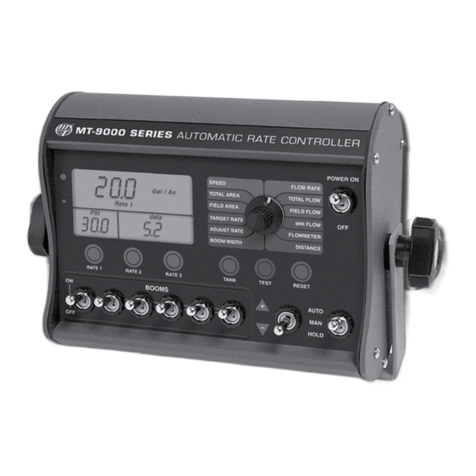
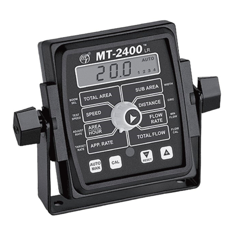
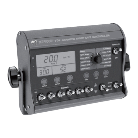
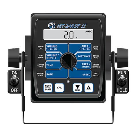
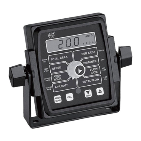
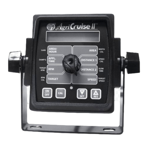
Other micro-trak Controllers manuals

micro-trak
micro-trak 17445 User manual

micro-trak
micro-trak MT-2405FTW II User manual

micro-trak
micro-trak MT-3405 F II User manual

micro-trak
micro-trak MT-9000 FTW User manual

micro-trak
micro-trak AgriCruise II User manual

micro-trak
micro-trak MT-400 LDI User manual

micro-trak
micro-trak MT-9000 Series User manual

micro-trak
micro-trak SprayMate II User manual

micro-trak
micro-trak MT-2400 LR User manual

micro-trak
micro-trak MT-3405F II User manual