CORNING ICH-02P User manual

P/N 003-1069-AEN
Issue 1
Standard Recommended Procedure 003-1069-AEN | Issue 1 | July 2019 | Page 1 of 6
Industrial Connector Housing
Quick Start Guide
(ICH-02P/ICH-06P)
• Visit www.corning.com/opcomm/safety for full safety precautions
1. Carton Contents
• Industrial connector housing
• Hardware Kit containing:
• (1) Label, 2 x 12 position
• (2) 6-32 locknuts
• (18) Cable ties
• (1) Universal cable clamp (UCC) kit
• (1) UCC bracket
• (1) Strength member strain-relief kit
WARNING: DO NOT use magniers in the
presence of laser radiation. Diused laser light
can cause eye damage if focused with optical
instruments. Should accidental eye exposure
to laser light be suspected, arrange for an eye
examination immediately.
CAUTION: Recommend the use of safety glasses
(spectacles) conforming to ANSI Z87, for eye
protection from accidental injury when handling
chemicals, cables, or working with ber. Pieces of
glass ber are very sharp and have the potential to
damage the eye.
WARNING: Never look directly into the end of a ber that may be carrying laser light. Laser light can be invisible
and can damage your eyes. Viewing it directly does not cause pain. The iris of the eye will not close involuntarily
as when viewing a bright light. Consequently, serious damage to the retina of the eye is possible. Should
accidental eye exposure to laser light be suspected, arrange for an eye examination immediately.
External door
Splice
cassette
holder
Radius control
guides
Fan-out
body
bracket
Fan-out
body
bracket
Ground
bar
02P Housing shown
Slack
storage
clips
TPA-6574
Sheath
retention
location

Standard Recommended Procedure 003-1069-AEN | Issue 1 | July 2019 | Page 2 of 6
2. Tools Required
• Phillips-head screwdriver
• Scissors
• 216B tool (can wrench)
• Pencil, pen or marker
3. Additional Materials (Purchased Separately)
May or may not be required depending on your application.
• Grounding kit (HDWR-GRND-KIT)
• Inner door lock kit (HDWR-LOCK-KIT)
• Padlock for front door
• Mounting hardware
• Buer tube fan-out kit (FAN-XX25-YY)
• CCH splice cassette (CCH-CSXX-YY-P00ZZ)
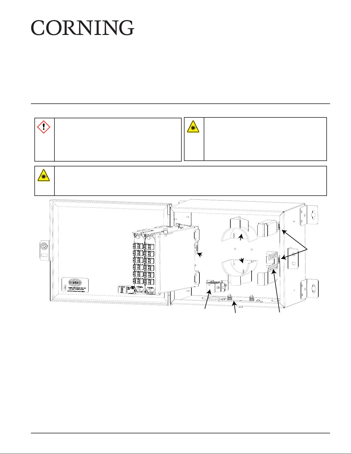
4. Mount the Housing
Step 1: Select a at vertical surface to prevent warping.
Step 2: Determine mounting location.
Step 3: Use a pencil, pen, or marker to mark the wall through the holes in the mounting brackets.
Step 4: Set unit aside and drive the mounting hardware (not provided) in at these locations leaving a 1/8-in
gap.
Step 5: Place housing on mounting hardware and tighten.
5. Housing Preparation (to maintain NEMA ratings)
IMPORTANT: If you are installing outside plant cable or temperature uctuates widely along any part of the
cable, the strength members of the cable must be strain-relieved. Failure to do so may result in
damage to the cable as temperature varies. Other situations only require the cable to be strain-
relieved by sheath retention only.
5.1 Install cord connectors
Step 1: Remove the grommets or knockouts, as applicable.
Step 2: Install cord connector with the knurled nut on the
outside of the housing.
Step 3: Orient the washers so that there is a gap between them
in the center as they are clamped together.
Step 4: Secure the cord connector on the inside of the housing
using the provided lock nut.
Step 5: Thread the cable through the tting and tighten the nuts.
5.2 Install conduit ttings
Step 1: Feed the cable through the ttings with the lager portion of the
tting on the outside of the housing and the smaller tting on the
inside.
Step 2: Screw the two ttings together.
IMPORTANT: For strength member strain-relief, use OSE-CBL-3X as the cable entry port tting. Install according
to the instructions provided with the kit.
Mounting Screws Not Provided
TPA-6575
Housing
Lock Nut
Reducing
Washer
Cord
Connector
Knurled
Nut
KPA-2176
KPA-2177

Standard Recommended Procedure 003-1069-AEN | Issue 1 | July 2019 | Page 3 of 6
6. Cable Preparation
6.1 Loose Tube Cable
Access 89 in of cable leaving 4 in of strength member
and 8 in of yarn, if present.
NOTE: Do not expose the bare ber until ready for termination.
6.2 Tight-Buered Cable
Access 56 in of cable leaving 4 in of
strength member and 4 in of yarn, if present.
6.3 Feeder Cable sheath retention strain-relief using the UCC
Step 1: Attach UCC bracket to housing using (2) 6-32 locknuts.
Step 2: Cut strength member(s) ush with outer jacket.
Step 3: Follow instructions provided with UCC kit to secure cable.
6.4 Feeder Cable strength member strain-relief
Follow instructions contained in the OSE-CBL-3X cable entry port
tting for the feeder cable.
Aramid Yarn (if present)
8 in (20 cm)
Strength Member
4 in (6 cm)
Buffer Tube
89 in (226 cm)
KPA-0178
Central Member:
4 in (10 cm)
Yarn: 4 in (10 cm)
900 micron or Tight-buffered Fibers:
56 in (142 cm)
TPA-6598
UCC Clamp
KPA-2178
Yarn
Ground cable
TPA-6578
Buffer tubes
Central member

Standard Recommended Procedure 003-1069-AEN | Issue 1 | July 2019 | Page 4 of 6
7. Grounding armored cable
Step 1: Use (1) HDWR-GRND-KIT per armored cable. Follow
instructions provided with kit to properly ground the
cable.
Step 2: Run ground wire from clamp on cable to ground
stud.
8. Feeder Cable Routing
Step 1: Route bers around radius guides.
Step 2: Install buer tube fanout bodies, if using CCH adapter panels
Step 3: Remove dust caps, clean, and mate connectors.
Ground
Stud
Ground Wire
KPA-2179
CAUTION: Fiber optic cable is sensitive to excessive pulling, bending, and crushing forces. Consult the cable
specication sheet for the cable you are installing. Do not bend the cable more sharply than the minimum
recommended bend radius. Do not apply more pulling force to the cable than specied. Do not crush the cable
or allow it to kink. Doing so may cause damage that can alter the transmission characteristics of the cable; the
cable may have to be replaced.
TPA-6576
CCH splice cassette
CCH adapter panel

Standard Recommended Procedure 003-1069-AEN | Issue 1 | July 2019 | Page 5 of 6
9. Drop Cable Routing
9.1 Drop Cable sheath retention strain-relief using cable ties
Step 1: If strain-relief using sheath retention alone is sucient, cut strength member(s) ush with the outer
jacket.
Step 2: Use two cable ties to secure cable to the strain-relief bracket.
9.2 Drop Cable strength member strain-relief
If strain-relief using the strength member is required:
Step 1: Remove drop cable strain-relief bracket.
Step 2: Install 8-32 x 5/8-in screw from the front side through the at washer and U-shaped washer.
Step 3: Loosely install the hex nut.
Step 4: Wrap the yarn, if present, in a clockwise direction around the screw and under the U-shaped washer.
Step 5: Insert the strength member of the cable between the at washer and the U-shaped washer.
Step 6: Tighten the hex nut.
NOTE: If the central member is metallic, see SRP 003-597.
Step 7: Trim o the excess yarn and central member.
Step 8: Reinstall the strain-relief bracket.
TPA-6577
Cable Ties
KPA-2184

Standard Recommended Procedure 003-1069-AEN | Issue 1 | July 2019 | Page 6 of 6
Corning Optical Communications LLC • PO Box 489 • Hickory, NC 28603-0489 USA
800-743-2675 • FAX: 828-325-5060 • International: +1-828-901-5000 • www.corning.com/opcomm
Corning Optical Communications reserves the right to improve, enhance, and modify the features and specications of Corning Optical Communications products without
prior notication. A complete listing of the trademarks of Corning Optical Communications is available at www.corning.com/opcomm/trademarks. All other trademarks are
the properties of their respective owners. Corning Optical Communications is ISO 9001 certied. © 2019 Corning Optical Communications. All rights reserved.
9.3 Route Drop Cable
Step 1: If installing an ICH-06P housing, route drop cable legs around the routing guides.
Step 2: Route connectorized legs through the routing clips in the side of the housing.
Step 3: Remove dust caps, clean, and mate connectors.
10. Finalize Installation
Step 1: Record ber identication on the label in a logical way and attach to inside of the front door.
Step 2: Attach laser warning label where it can easily be seen inside the housing.
Step 3: Close door with a 216B tool (can wrench).
Step 4: Use a pad lock to secure housing.
ICH-02P
ICH-06P
TPA-6597
This manual suits for next models
1
Table of contents
Other CORNING Industrial Equipment manuals