Corning Cable Systems
Standard Recommended Procedure (SRP) 003-544
Issue 6, May 2004
Page 1 of 26
SCF-6 and SCF-8 Open Ribbon System (ORS) Canister Splice Closures
p/n 003-544
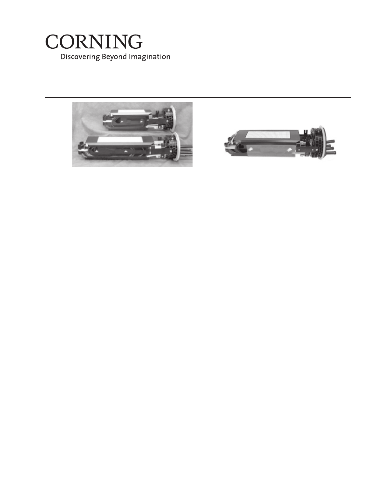
SCF-8
Figure 1 — Splice Closures
SCF-6
Contents
Related Literature ...................................................................................................................2
Admonishments.......................................................................................................................2
1. Carton Contents ...............................................................................................................................3
2. Tools and Equipment Required .......................................................................................................4
3. Installing the Closure .......................................................................................................................4
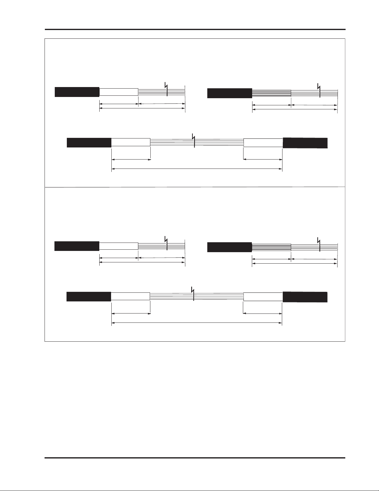
3.1 Prepare the Express Cable ......................................................................................................4
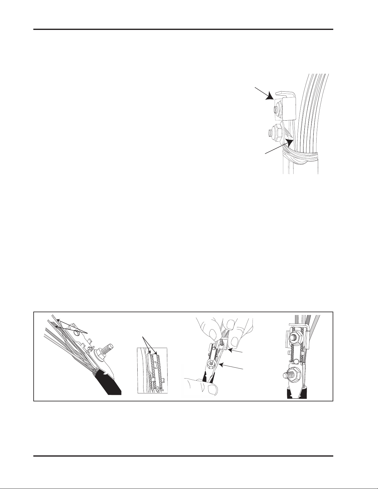
3.2 Install Grounding Hardware (Armored Cable Only) ............................................................6
3.3 Install Express Strain-relief Hardware ................................................................................... 7
3.3.1 Strain-relief bracket(s) ................................................................................................7
3.3.2 Nonmetallic strength member ...................................................................................8
3.3.3 Metallic strength members ........................................................................................8
3.3.4 Large strength members ............................................................................................9
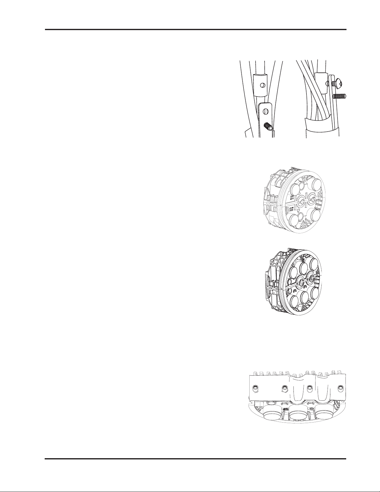
3.4 Install Cable into the End Cap Express Ports ........................................................................ 9
3.4.1 Prepare the end cap ....................................................................................................9
3.4.2 Apply sealing tape to the cable ................................................................................. 10
3.4.3 Using dummy plug ...................................................................................................11
3.4.4 Install cable ...............................................................................................................11
3.4.5 Close end cap halves .................................................................................................11
3.4.6 Install vented grounding plug ..................................................................................12
3.4.7 Complete frame assembly ........................................................................................12
3.5 Ground Armored Cable ........................................................................................................12
3.6 Prepare Drop Cable Port(s) ..................................................................................................12
3.7 Install Drop Port Cable into End Cap .................................................................................14
3.8 Strain-relieve Drop Ports .....................................................................................................14
3.9 Attach Strain-relief Bracket ..................................................................................................15
3.10 Tighten End Cap Compression Screw.................................................................................15
3.11 Attach Frame to End Cap .....................................................................................................16
3.12 Load the ORS .......................................................................................................................16
3.12.1 Route express fibers ..................................................................................................16
3.12.2 Route drop cable fibers ............................................................................................18
3.12.3 Route fibers to the splice plane ................................................................................18
3.13 Splice .....................................................................................................................................19
3.13.1 Prepare fibers for splicing ........................................................................................ 19
3.13.2 Splice fibers...............................................................................................................19