Cognex DataMan 374 User manual

INSTALL GUIDE
COGNEX DataMan 374

TABLE OF CONTENTS
iiINSTALL GUIDE
COGNEX DataMan 374
1 INSTALLATION 1
1.1 Mounting the Cognex Reader 2
1.1.1 Mounting Height 3
1.1.2 Mounting Angle 3
1.1.3 Code Reading direction 5
1.2 Installation for Collate & OMR Folder Reading Interface 6
1.2.1 Cable Routing 6
1.2.2 Cable Looping 7
1.3 Installation for Insert Feeder Interface 8
1.4 Connecting to the Barcode Interface Board 9
1.5 Connecting the Reader to the IMOS PC 11
1.5.1 Connecting a Single Reader 12
1.5.2 Connecting Multiple Readers 12
2 SOFTWARE SETUP 14
2.1 Important Cognex Software Information 15
2.2 Obtaining the Reader IP Address 16
2.3 Read-Head Orientation 17
2.4 Load to Reader 18
2.5 Reader Alignment 22
2.6 Reader Calibration 24
3 KEY FEATURES 25
3.1 Cognex Dataman 374 Features and Indicators 26

1INSTALL GUIDE
COGNEX DataMan 374
1
INSTALLATION

2
DEC 2021
INSTALL GUIDE
1INSTALLATIONCOGNEX DataMan 374
REV 00
1.1 MOUNTING THE COGNEX READER
There are two Cognex Reader kit versions available (top-read, and bottom-read)
as follows:
▪A0128487 - BCR/2D COGNEX RDR TOP
▪A0128486 - BCR/2D COGNEX RDR BOTTOM
Both top-read shown in Figure 1.1, and bottom-read shown in Figure 1.2 may be
mounted in either horizontal or vertical orientation.
QTL-RND-OPS-00000301-A-00
Figure 1.1 – Top-read mounted in horizontal and vertical orientation
NOTE:
Arrow represents code read direction.
QTL-RND-OPS-00000302-A-00
Figure 1.2 – Bottom-read mounted in horizontal and vertical orientation
NOTE:
Arrow represents code read direction.

3
DEC 2021
INSTALL GUIDE
1
INSTALLATION
COGNEX DataMan 374
REV 00
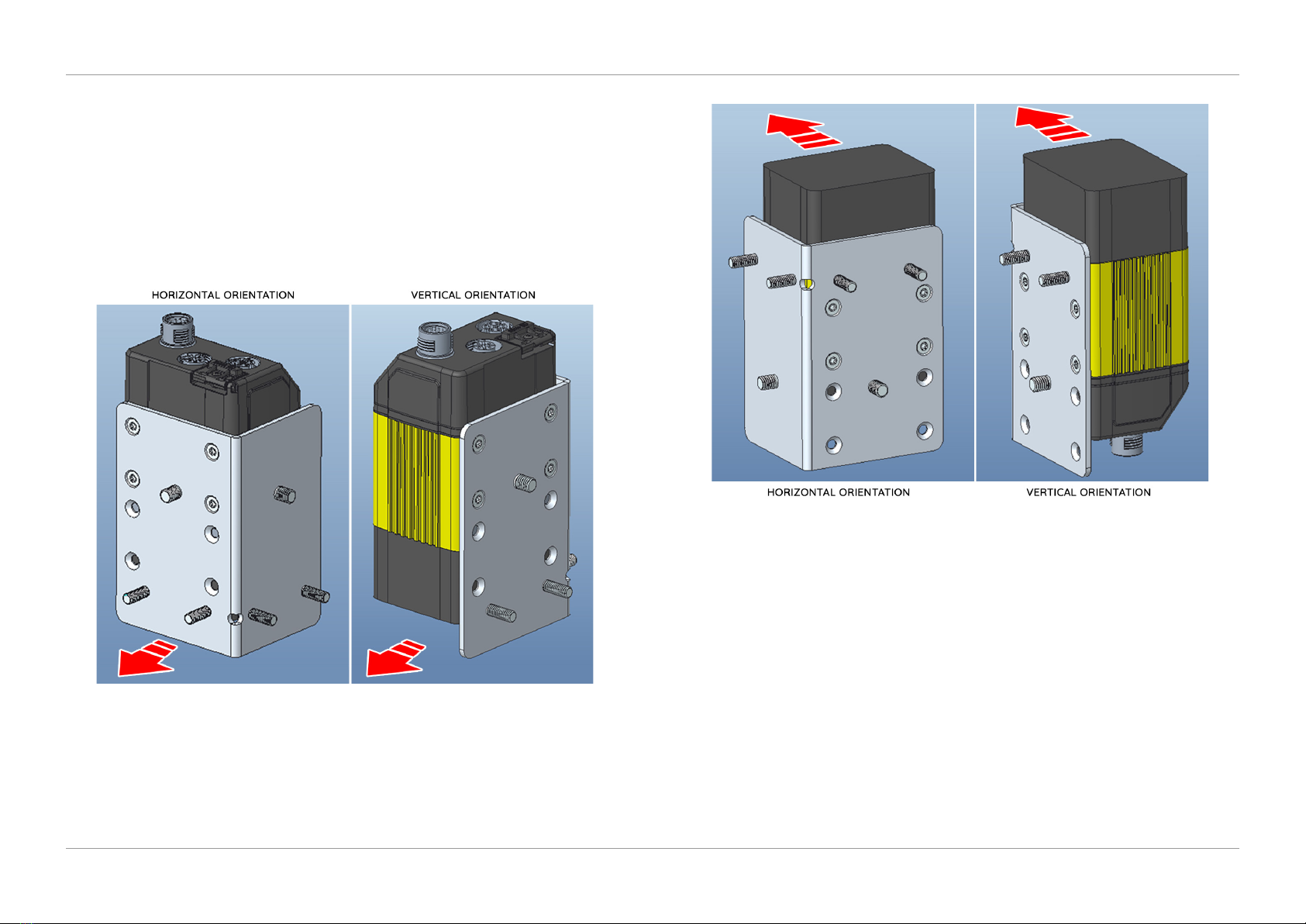
1.1.1 MOUNTING HEIGHT
1. To set the height, attach the Cognex Reader assembly to the Vertical Head
Bracket (9107481J).
2. Ensure the reader mount ‘lug’ locates into position for either top-read or
bottom-read as shown in Figure 1.3.
QTL-RND-OPS-00000303-A-00
Figure 1.3 – Reader mount lug located into position
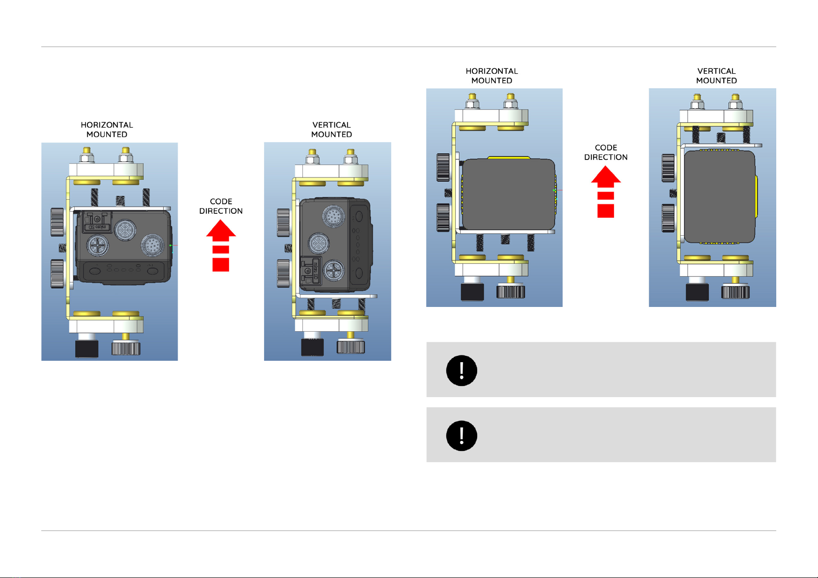
3. Attach the Reader assembly to the vertical head bracket with the two thumb
lock knobs.
Bracket mount must be orientated correctly to achieve a nominal
distance of 110mm from the paper surface.
1.1.2 MOUNTING ANGLE
1. To set the angle, un-tighten the thumb lock knob for either top-read or
bottom-read as shown in Figure 1.4.
QTL-RND-OPS-00000304-A-00
Figure 1.4 – Un-tightening the thumb lock knobs
The small thumb lock knob allows adjustment of the angle, and
the larger thumb lock knob allows adjustment of the side to side
position.

4
DEC 2021
INSTALL GUIDE
1
INSTALLATION
COGNEX DataMan 374
REV 00
2. Depending on the code reading direction on the document, rotate the Reader
and Bracket completely left or right (15 degrees nominal) as shown in Figure
1.5 for top-read, and similarly for bottom-read shown in Figure 1.6.
QTL-RND-OPS-00000305-A-00
Figure 1.5 – Rotating left or right for top-read
QTL-RND-OPS-00000306-A-00
Figure 1.6 – Rotating left or right for bottom-read
3. Re-tighten the thumb lock knob once the desired setting has been achieved.

5
DEC 2021
INSTALL GUIDE
1
INSTALLATION
COGNEX DataMan 374
REV 00
1.1.3 CODE READING DIRECTION
Observe the following Code reading direction in Figure 1.7 and Figure 1.8 for both
horizontal and vertical mounted readers.
QTL-RND-OPS-00000307-A-00
Figure 1.7 – Top-read code direction
QTL-RND-OPS-00000308-A-00
Figure 1.8 – Bottom-read code direction
Ensure the correct read-head orientation has been selected for the
job prior to alignment and calibration. See section 2.3 Read-Head
Orientation for further assistance.
When switching between Horizontal and Vertical barcode
positions, it is recommended to recalbrate the reader after the
change. See section 2.5 Reader Calibration for further assistance.

6
DEC 2021
INSTALL GUIDE
1
INSTALLATION
COGNEX DataMan 374
REV 00
1.2 INSTALLATION FOR COLLATE & OMR FOLDER READING INTERFACE
Mount the reader as required following the procedures detailed in section 1.1 Mounting
the Cognex Reader.
When installing, begin from the Reader back to the board to
ensure any excess cable can be tied back into the reader section.
Figure 1.9 shows the Reader mounting bracket located in its xed position for top-read
and bottom-read.
QTL-RND-OPS-00000309-A-00
Figure 1.9 – Reader mounting bracket located in xed position
1.2.1 CABLE ROUTING
Route the reader cables accordingly using cable ties where necessary following
Figure 1.10, and Figure 1.11.
QTL-RND-OPS-00000310-A-00
Figure 1.10 – Reader cable routing

7
DEC 2021
INSTALL GUIDE
1
INSTALLATION
COGNEX DataMan 374
REV 00
QTL-RND-OPS-00000311-A-00
Figure 1.11 – Reader cable routing
1.2.2 CABLE LOOPING
Cable looping ensures the correct cable length required for both horizontal and vertical
mounted readers when in their maximum left or right positions as shown in Figure 1.12
and Figure 1.13, Figure1.14, and Figure 1.15.
QTL-RND-OPS-00000312-A-00
Figure 1.12 – Horizontal mounted reader in maximum left position
QTL-RND-OPS-00000313-A-00
Figure 1.13 – Horizontal mounted reader in maximum right position

8
DEC 2021
INSTALL GUIDE
1
INSTALLATION
COGNEX DataMan 374
REV 00
QTL-RND-OPS-00000314-A-00
Figure 1.14 – Vertical mounted reader in maximum left position
QTL-RND-OPS-00000315-A-00
Figure 1.15 – Vertical mounted reader in maximum right position
1.3 INSTALLATION FOR INSERT FEEDER INTERFACE
Installation procedures for a Feeder unit is the same as for a Collate unit. Follow the
same procedures detailed in section 1.2 Installation for Collate & OMR Folder Reading
Interface.
When installing, begin from the Reader back to the board to
ensure any excess cable can be tied back into the reader section.
Figure 1.16 and Figure 1.17 shows the bottom-read reader mounted horizontally and
vertically for a Feeder Reading Interface.
QTL-RND-OPS-00000316-A-00
Figure 1.16 – Bottom-read horizontally mounted reader

9
DEC 2021
INSTALL GUIDE
1
INSTALLATION
COGNEX DataMan 374
REV 00
QTL-RND-OPS-00000317-A-00
Figure 1.17 – Bottom-read vertically mounted reader
1.4 CONNECTING TO THE BARCODE INTERFACE BOARD
The procedure for connecting the reader to the Barcode Interface Board for both a
Collate and OMR Folder Reading Interface and Insert Feeder Interface are made in the
same manner.
Figure 1.18 shows the reader connected to the Barcode Interface Board (A0133330) for
a Collate unit.
QTL-RND-OPS-00000320-A-00
Figure 1.18 – Barcode Interface Board connection for a Collate unit

10
DEC 2021
INSTALL GUIDE
1
INSTALLATION
COGNEX DataMan 374
REV 00
Figure 1.19 shows the reader connected to the Barcode Interface Board (A0133330) for
reading from a Feeder unit.
QTL-RND-OPS-00000321-A-00
Figure 1.19 – Barcode Interface Board connection for a Feeder unit
Barcode Interface Board Rev. C is required as a minimum for both
a Collate and Feeder unit.
Connect the Cognex Reader as required to ‘J1’ connection point for Reader 1, or ‘J2’
connection point for Reader 2 on the Barcode Interface Board as shown in Figure 1.20.
QTL-RND-OPS-00000322-A-00
Figure 1.20 – Connecting to the Barcode Interface Board

11
DEC 2021
INSTALL GUIDE
1
INSTALLATION
COGNEX DataMan 374
REV 00
NOTE:
S1 Set toggle switch to ‘Normal’ for single and multiple readers.
S2 Set toggle switch to ‘Default’ for a single reader, and ‘All On’ for
multiple readers.
J10, J11 A0117569 (XE169) or 9100703Y and 9100720R (C167)
J31 Collate/OMR Folder 9105223G and Insert Feeder, Track 9107507L
Toggle Switch S1 must be set to ‘NORMAL’ for both single and
multiple Cognex Readers setups. Toggle switch S2 must be set to
‘DEFAULT’ for single and ‘ALL ON’ for multiple Cognex Readers as
shown in Figure 1.22.
1.5 CONNECTING THE READER TO THE IMOS PC
The DS1200 M/C can be tted with either a single reader or multiple readers.
Single Reader
If a single reader is tted, the USB/Ethernet Adapter (A0014392) can be plugged
directly into an available USB port (Front/Back) on the IMOS PC.
Multiple Readers
If multiple readers are tted, the following Multi-Reader Kit is available to order:
▪A0135969 DataMan Viewer Kit (Max. 4 Readers per kit)
Figure 1.21 shows the parts required to connect a Cognex DataMan 374 to the IMOS PC
allowing the viewing of images in the Reader Setup Screen within IMOS.
QTL-RND-OPS-00000324-A-00
Figure 1.21 – Cognex DataMan 374 connection parts
To connect a single reader or multiple readers, rst route the RJ45/Ethernet cable
supplied with the reader kit, from the reader through the DS-1200 machine following
the details set out in section 1.2.1 Cable Routing and section 1.2.2 Cable Looping.

12
DEC 2021
INSTALL GUIDE
1
INSTALLATION
COGNEX DataMan 374
REV 00
1.5.1 CONNECTING A SINGLE READER
1. To connect a single reader, connect the other end of the RJ45/Ethernet cable
to the USB/Ethernet Adapter (A0014392) supplied with the reader kit as shown
in Figure 1.22.
QTL-RND-OPS-00000325-A-00
Figure 1.22 – Connecting the green ethernet cable to USB/ethernet adapter
2. Then plug the USB/Ethernet Adapter into an available USB port (Front/Back)
on the IMOS PC.
1.5.2 CONNECTING MULTIPLE READERS
1. To connect multiple readers, connect the other end of the RJ45/Ethernet
cable to the USB/Ethernet Adapter (A0014392) as shown in Figure 1.22, for as
many readers required (up to a maximum of 4 readers per kit).
2. Plug the USB Switch Hub (A0135968) into any available USB port (Front/Back)
on the IMOS PC.
3. Then plug the USB/Ethernet Adapter from the ‘Prime station’ into the left USB
port on the USB Switch Hub, which will be ‘Reader 1’.
4. Each additional reader must be plugged into the next adjacent available USB
port as shown in Figure 1.23, (up to a maximum of 4 readers per kit).
QTL-RND-OPS-00000326-A-00
Figure 1.23 – Plugging the USB/ethernet adapter into the USB switch hub

13
DEC 2021
INSTALL GUIDE
1
INSTALLATION
COGNEX DataMan 374
REV 00
Figure 1.24 shows multiple Cognex readers installed and wired.
QTL-RND-OPS-00000333-A-00
Figure 1.24 – Multiple Cognex Readers installed and wired
NOTE:
Once the reader is plugged in, the reader IP address must be obtained,
see section 2.2 Obtaining the Reader IP Address for further assistance.

14INSTALL GUIDE
COGNEX DataMan 374
2
SOFTWARE SETUP

15
DEC 2021
INSTALL GUIDE
2SOFTWARE SETUPCOGNEX DataMan 374
REV 00
2.1 IMPORTANT COGNEX SOFTWARE INFORMATION
The Cognex DataMan 374 is supported on the DS-1200 G4i for
software release R0065 onwards. Please contact your local
support team for further information.
The IP address of the camera port must be setup as follows.
1. Navigate to Windows Network Ethernet Settings on the IMOS PC, select
‘Internet Protocol Version 4 (TCP/IPv4)’, then select ‘Properties’ as shown in
Figure 2.1.
QTL-RND-SCR-00000272-A-00
Figure 2.1 – Selecting Internet Protocol Version 4 Properties
2. Enter the following IP address, then click ‘OK’ once complete as shown in
Figure 2.2.
QTL-RND-SCR-00000273-A-00
Figure 2.2 – Entering the IP address
NOTE:
This will be the IP address of the unit, and the 3rd number shown in Figure 2.2
will be the unit that the camera is tted to.

16
DEC 2021
INSTALL GUIDE
2
SOFTWARE SETUP
COGNEX DataMan 374
REV 00
2.2 OBTAINING THE READER IP ADDRESS
The IP address of each reader can be found by going into Reader Setup within IMOS
and selecting the channel required to obtain the IP address information
1. Navigate to the IMOS Menu screen, select ‘Service’, and then ‘Reader Setup’
from the list as shown in Figure 2.3.
QTL-RND-SCR-00000240-A-00
Figure 2.3 – Selecting reader setup
2. In the Reader Setup screen, select the required unit and reader channel to
obtain the IP address information as shown in Figure 2.4.
QTL-RND-SCR-00000274-A-00
Figure 2.4 – Obtaining the IP address of the reader
NOTE:
The 3rd number in the IP address corresponds to the unit that the camera is
tted to as shown in Figure 2.4.
3. Ensure communication between the Insert Head and Cognex Reader is
present by checking the displayed information in the bottom right pane of the
Reader Setup screen as shown in Figure 2.5.
QTL-RND-SCR-00000275-A-00
Figure 2.5 – Reader communication information
4. Once connected, the reader will need to be aligned. See section 2.4 Load to
Reader and section 2.5 Reader Alignment for further assistance.
Ensure the correct read-head orientation has been selected for the
job prior to alignment and calibration. See section 2.3 Read-Head
Orientation for further assistance.

17
DEC 2021
INSTALL GUIDE
2
SOFTWARE SETUP
COGNEX DataMan 374
REV 00
2.3 READ-HEAD ORIENTATION
The correct orientation of the read-head must be selected in the Jobs screen within
IMOS for a particular job that requires reading.
1. Navigate to the Jobs screen and dene a new mailset, or edit an existing one.
2. Select the settings of the unit that the reader is installed on (i.e. Unit 2:
Feeder), then select ‘Read-head orientation’ under the list of reading control
settings as shown in Figure 2.6.
QTL-RND-SCR-00000266-A-00
Figure 2.6 – Reading control settings
3. Select the read-head orientation from the list as shown in Figure 2.7, then
select ‘Ok’ once complete.
QTL-RND-SCR-00000266-A-00
Figure 2.7 – Selecting the read-head orientation
The read-head orientation must match the same orientation that
the camera reader has been mounted in the unit (e.g. Vertical
or Horizontal), see section 1.1 Mounting the Cognex Reader for
further information.

18
DEC 2021
INSTALL GUIDE
2
SOFTWARE SETUP
COGNEX DataMan 374
REV 00
2.4 LOAD TO READER
Load to Reader is used to feed one document under the reader so you can position
the reader to the label.
1. From the run screen within IMOS, select the unit number that the reader is
installed on (i.e. unit ‘6’ collator) as shown in Figure 2.8.
QTL-RND-SCR-00000266-A-00
Figure 2.8 – Selecting the reader unit
2. Select the ‘Load to Reader’ option in the unit ne tuning screen as shown in
Figure 2.9.
QTL-RND-SCR-00000267-A-00
Figure 2.9 – Selecting Load to Reader
3. Click ‘Ok’ in the conrmation dialog box as shown in Figure 2.10.
QTL-RND-SCR-00000268-A-00
Figure 2.10 – Conrming Load to Reader
Table of contents
Other Cognex Industrial Equipment manuals
Popular Industrial Equipment manuals by other brands

FLENDER
FLENDER FASTEX IN110 Assembly and operating instructions

Orion
Orion 39552 user manual

SKF
SKF TMMA 100H/SET Instructions for use

SMC Networks
SMC Networks EX12 SCS Series Operation manual

Phoenix Contact
Phoenix Contact FL MGUARD 1000 Series Installation and startup guide

Schmalz
Schmalz SSP operating manual