manuals.online logo
Brands
  1. Home
  2. •
  3. Brands
  4. •
  5. Eaton
  6. •
  7. Power Distribution Unit
  8. •
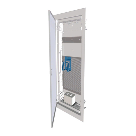
  9. Eaton StructuredWiringSolutions ESWT41600 Manual

Eaton StructuredWiringSolutions ESWT41600 Manual

Other Eaton Power Distribution Unit manuals

Eaton Managed ePDU User manual

Eaton

Eaton Managed ePDU User manual

Eaton Crouse-hinds series Setup guide

Eaton

Eaton Crouse-hinds series Setup guide

Eaton xComfort CBEU-02/01 User manual

Eaton

Eaton xComfort CBEU-02/01 User manual

Eaton Powerware Series User manual

Eaton

Eaton Powerware Series User manual

Eaton EPBZ99 User manual

Eaton

Eaton EPBZ99 User manual

Eaton DMVS160N Manual

Eaton

Eaton DMVS160N Manual

Eaton Advanced Enclosure Power Distribution Unit... User manual

Eaton

Eaton Advanced Enclosure Power Distribution Unit... User manual

Eaton ePDU G3 Operating and maintenance manual

Eaton

Eaton ePDU G3 Operating and maintenance manual

Eaton RAMO5 A Series Manual

Eaton

Eaton RAMO5 A Series Manual

Eaton AUX1NO+1NCDMM Manual

Eaton

Eaton AUX1NO+1NCDMM Manual

Eaton DMV160N Manual

Eaton

Eaton DMV160N Manual

Eaton SPD Series User manual

Eaton

Eaton SPD Series User manual

Eaton Pow-R-Line P2R Series User manual

Eaton

Eaton Pow-R-Line P2R Series User manual

Eaton 650 FR User manual

Eaton

Eaton 650 FR User manual

Eaton Cutler-Hammer Digitrip RMS 510 Trip Unit User manual

Eaton

Eaton Cutler-Hammer Digitrip RMS 510 Trip Unit User manual

Eaton PXS24 Series User manual

Eaton

Eaton PXS24 Series User manual

Eaton FlexPDU User manual

Eaton

Eaton FlexPDU User manual

Eaton Powerware 9390 User manual

Eaton

Eaton Powerware 9390 User manual

Eaton MBP6Ki User manual

Eaton

Eaton MBP6Ki User manual

Eaton ePDU G3 User manual

Eaton

Eaton ePDU G3 User manual

Eaton ePDU User manual

Eaton

Eaton ePDU User manual

Eaton Mini PDU User manual

Eaton

Eaton Mini PDU User manual

Eaton PXS24 Series User manual

Eaton

Eaton PXS24 Series User manual

Eaton Powerware 225 kVA Three-Phase Power Distribution... User manual

Eaton

Eaton Powerware 225 kVA Three-Phase Power Distribution... User manual

Popular Power Distribution Unit manuals by other brands

Lightcorp Nik installation instructions

Lightcorp

Lightcorp Nik installation instructions

hager SP 015 User instructions

hager

hager SP 015 User instructions

Pakedge PowerPak 9 user guide

Pakedge

Pakedge PowerPak 9 user guide

Pts 9042 Series installation guide

Pts

Pts 9042 Series installation guide

Shure WA405 user guide

Shure

Shure WA405 user guide

CORNING CCH 4U quick start guide

CORNING

CORNING CCH 4U quick start guide

Panamax M4LT-EX datasheet

Panamax

Panamax M4LT-EX datasheet

PANCONNECT FLAT 3M Assembly instruction

PANCONNECT

PANCONNECT FLAT 3M Assembly instruction

Raytheon 138-118 manual

Raytheon

Raytheon 138-118 manual

StarTech.com RKPW161915 Spec sheet

StarTech.com

StarTech.com RKPW161915 Spec sheet

D&R ELECTRONICS PDU-6SS user manual

D&R ELECTRONICS

D&R ELECTRONICS PDU-6SS user manual

Botex PSA 322-6 DL quick start guide

Botex

Botex PSA 322-6 DL quick start guide

GE QuiXtra 4000 Assembly and mounting instructions

GE

GE QuiXtra 4000 Assembly and mounting instructions

Vertiv Knürr DI-Strip Rack PDU manual

Vertiv

Vertiv Knürr DI-Strip Rack PDU manual

ABB PSBS0065 Instruction handbook

ABB

ABB PSBS0065 Instruction handbook

Baumuller BFN 3-1-0007-001 Instruction handbook

Baumuller

Baumuller BFN 3-1-0007-001 Instruction handbook

GE GEK-45404F instructions

GE

GE GEK-45404F instructions

Huawei PDU8000 Series user manual

Huawei

Huawei PDU8000 Series user manual

manuals.online logo
manuals.online logoBrands
  • About & Mission
  • Contact us
  • Privacy Policy
  • Terms and Conditions

Copyright 2025 Manuals.Online. All Rights Reserved.

PRELIMINARY DRAFT
StructuredWiringSolutions

Installation Guide
ESWT41600
Instruction Leaflet IL00412001E
Proof #5 — Zoltun Design — May 2, 2006
Effective March 2006
Description
The Eaton ESWT41600 Telephone Distribution Module provides
distribution of four incoming telephone lines to 16 locations. Please
be sure to review this installation guide carefully prior to installation.
Features
●
Four telephone lines to 16 phone locations, or two groups of 8.
●
Two Incoming Service Connections.
●
Two RJ45 linking jacks.
●
RJ45 output connections.
●
RJ31X jack for security.
FIGURE 1.
Option A: Installing Phone Line to All 16 Outputs
1. Run a CAT5e twisted pair cable from the NID (network interface
device) / D-mark location (this is the box installed by the phone
company on the side of the home) to the ESWT41600 and
connect the cable to the Incoming Service Connection using a
110-style punch-down. (See
Figure 1
.)
2. Identify the CAT5e wire running from the ESWT41600 to each of
the rooms. (This is known as premise wiring.)
3. Remove 2 inches of the outer PVC jacket from the end of the
premise wire, exposing the four pairs of wire underneath.
4. Terminate these wire pairs with a RJ45 Modular Telephone plug
following the 568 A termination. (See
Figure 2
.)
Link Ports
Incoming Service
Connection
RJ31X Port
4-Line, 16-Location Telephone Distribution Module
FIGURE 2.
Pin 1
1234 5678
1
2
34
Pair No.
132456
78
Pin
1
2
3
4
5
6
7
8
Color
white/green
green
white/orange
blue
white/blue
orange
white/brown
brown
EIA/ITA 568 A
RJ-45 Plug
568 A
PRELIMINARY DRAFT
Proof #5 — Zoltun Design — May 2, 2006
Eaton Electrical Inc.
1000 Cherrington Parkway
Moon Township, PA 15108-4312
United States
tel: 1-800-525-2000
www.EatonElectrical.com
© 2006 Eaton Corporation
All Rights Reserved
Printed in USA
Publication No. IL00412001E / Z4022
April 2006
5. Now connect the 8-inch link cable (CAT5e patch cord) to both of
the Link Ports. If you are also connecting a security system, use
the RJ31X Port. (See
Figure 3
.)
6. Connect the terminated CAT5e premise wire to any of the 16
RJ45 outputs on the front of the ESWT41600. (See
Figure 3
.)
FIGURE 3.
Option B: Splitting the 16 Outputs Into Two Groups of Eight
1. Run CAT5e twisted pair cable from the Network Interface Device
(NID) / D-mark location to the ESWT41600.
2. Connect the CAT5e cables for the first group of eight outputs to
the appropriate incoming service connector. Use a 110-style
punch down where Line 1 (Blue/White and Blue Solid) and Line 2
(Orange/White and Orange Solid) connect to the blue and orange
positions on the Incoming Service Connection.
3. For the second group of eight outputs, connect Line 3 (Green/
White and Green Solid) and Line 4 (Brown/White and Brown
Solid) to the blue and orange positions on the Second Incoming
Service Connection. (See
Figure 4
.)
4. Connecting the ESWT41600 in this manner will now give you
access to a different phone line in two groups of eight. (See
Figure 4
.)
Important:
Make sure that the Link Cable is not used
in this type of installation.
FIGURE 4.
Link Cable
Incoming Phone
Service
RJ31X Port to the
Security System
Incoming
Phone Lines
Installing the ESWT41600 With a Security System
Use the jack on the back of the ESWT41600 marked for security only
to connect phone service to a security system. The RJ31X jack will
use whichever phone line is associated with the blue CAT5e pair on
the incoming cable. On the RJ31X jack, pins 5 and 4 take the phone
signal to the security system, and pins 1 and 8 bring the phone signal
back to the module. Make sure that the Tip (T) and Ring (R) are in the
correct position. (See
Figure 5
.)
FIGURE 5.
Incoming Phone
Line (Take to
Security System)

House Phone
(From Security System)