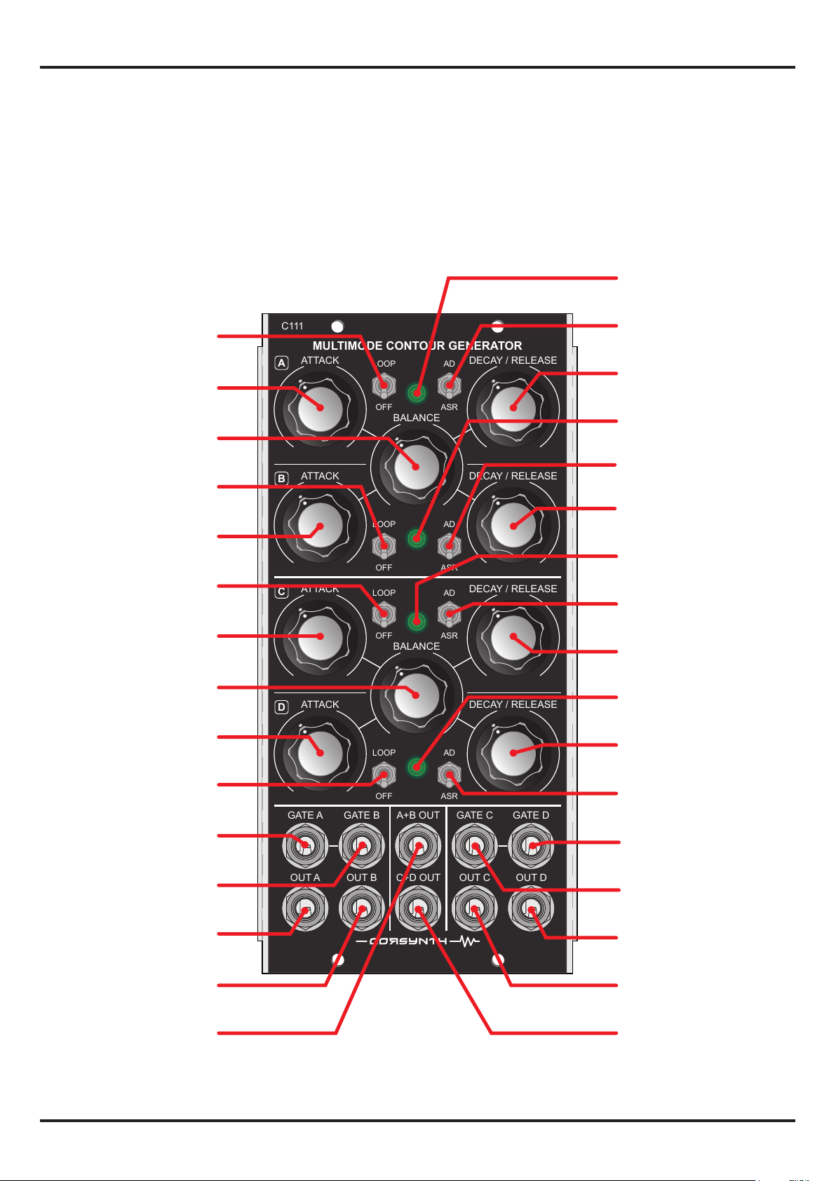
c111 multImode CONTOUR GENERATOR
8
HTTP://WWW.CORSYNTH.COM
MIN MAX
MIN MAX
MIN MAX
MIN MAX
A B
MIN MAX
MIN MAX
MIN MAX
MIN MAX
A B
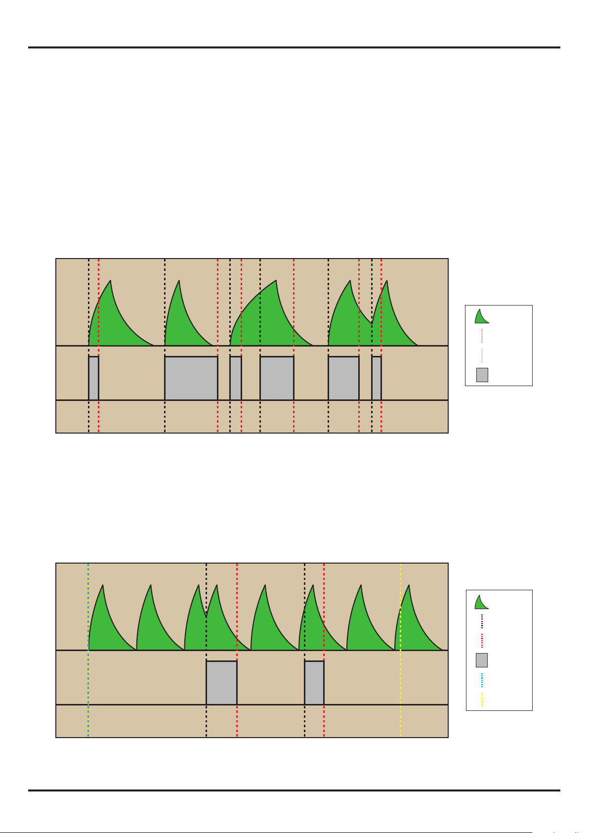
Envelope
Gate
ADSR ( Attack - Decay - Sustain - Release )
The more typical synthesizer envelope. To obtain an ADSR, one envelope has to be set to AD and the
other to ASR. Attack times should be the same in both envelopes. The Decay time is determined by
the AD envelope and the release time by the ASR envelope. The BALANCE knob sets the Sustain level,
the more ASR envelope ( in this case B ) the sustain level will be higher. The only dierence with a
normal ADSR is that in case the gate signal is removed before the end of the attack phase , the AD
envelope will complete anyway its full cycle .
ADASR ( Attack - Decay - Attack - Sustain - Release )
This is a variation of the ADSR envelope. It has an Attack-Decay phase followed by a second Attack
until reach the Sustain level. As before one envelope has to be set to AD and the other to ASR. The
Attack and Decay time of the AD envelope should be short, especially the Decay time. In total the AD
envelope has to be shorter than the Attack time of the ASR envelope. The BALANCE knob sets the
Sustain level but it also aects the Attack phase, with more ASR envelope the rst Attack-Decay
phase will be less accentuated.
Envelope
Gate
USING THE MIX OUTPUTS ( A+B , C+D)
One of the more interesting features of the C111 is the possibility to combine two envelopes to
create new envelope shapes. Using the A+B and C+D outputs is easy to obtain envelopes not possi-
ble using a normal envelope generator. This section explain how to set up the module to create those
kind of envelopes. The knobs in the examples, are set to obtain the envelope times shown in the
graphics. Shorter or longer times are possible for every kind of envelope. Since these envelopes are
obtained adding and subtracting signals, some of them will not reach the typical 5V peak. The
graphic resolutions are, vertical 2 volts/division and horizontal 1 second/division.