Carrier Fireye NXTSD507HD Owner's manual

© 2021 Carrier 1
TSD-4001
August 1, 2021
NXTSD507HD, NXTSD512HD
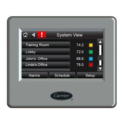
Touchscreen Interface
Installation and Operation
DESCRIPTION
This bulletin describes the installation and operation of the NXTSD507HD (7”) and NXTSD512HD
(12.1”) touchscreen interfaces. An overview of navigation through the available data as well as device-
specific information is covered.
These optional devices allow for enhanced and expanded connectivity to the NXF4000 and PPC4000
parallel-positioning systems. This bulletin is intended to be a supplement to the specific bulletin for
any connected control. Those bulletins may be specified in this document. Please refer to those
bulletins for any specific information on installation, features, commissioning or operation of the
connected controls.
WARNING: Failure to properly install, operate, or commission the equipment
in this manual could result in significant property damage, severe injury, or
death. It is the responsibility of the owner or user to ensure that the
equipment described is installed, operated and commissioned in compliance
with this manual as well as the manuals of other system components, as
well with all applicable national and local codes.
WARNING: Boiler operation, maintenance, and troubleshooting shall only be
conducted by trained personnel. Persons troubleshooting lockouts or
resetting the control must respond properly to troubleshooting error codes as
described in this product bulletin. Jumpers being used to perform static test
on the system must only be used in a controlled manner and must be removed
prior to the operation of the control. Such tests may verify the external
controllers, limits, interlocks, actuators, valves, transformers, motors and
other devices are operating properly. Such tests must be conducted with
manual fuel valves in the closed position only. Replace all limits and interlocks
not operating properly, and do not bypass limits in interlocks. Failure to follo
w
these guidelines may result in an unsafe condition hazardous to life and
property.

2 © 2021 Carrier
TABLE OF CONTENTS
DESCRIPTION .............................................................................................................................................................1
SYSTEM INFORMATION...........................................................................................................................................4
TECHNICAL DATA NXTSD507HD...........................................................................................................................5
TECHNICAL DATA NXTSD512HD...........................................................................................................................6
ORDERING INFORMATION......................................................................................................................................7
MOUNTING NXTSD507HD .......................................................................................................................................8
Method ......................................................................................................................................................................8
Cutout........................................................................................................................................................................9
Template..................................................................................................................................................................10
MOUNTING NXTSD512HD .....................................................................................................................................11
Method ....................................................................................................................................................................11
Cutout......................................................................................................................................................................12
WIRING ......................................................................................................................................................................13
Terminals.................................................................................................................................................................13
Wiring .....................................................................................................................................................................14
Ethernet/USB ..........................................................................................................................................................16
ESTABLISHING COMMUNICATION .....................................................................................................................17
OVERVIEW SCREEN (NXF4000 and PPC4000) .....................................................................................................18
INFORMATION SCREEN (NXF4000 and PPC4000)...............................................................................................19
GENERAL SETTINGS (NXF4000 and PPC4000) ....................................................................................................20
Changing values ......................................................................................................................................................20
SYSTEM SETTINGS..................................................................................................................................................21
ALARMS ....................................................................................................................................................................22
Active ......................................................................................................................................................................23
Log ..........................................................................................................................................................................24
Fault History............................................................................................................................................................25
HELP ...........................................................................................................................................................................26
SYSTEM .....................................................................................................................................................................27
Log ..........................................................................................................................................................................28
Security ...................................................................................................................................................................29
Options ....................................................................................................................................................................31
Miscellaneous .....................................................................................................................................................31
Language ............................................................................................................................................................39
Screen Saver / Date.............................................................................................................................................40
Network ..............................................................................................................................................................41
Modbus Data Server ...........................................................................................................................................42
OVERVIEW SCREEN (BurnerLogix) .......................................................................................................................45
WIRING DIAGRAM SCREEN (BurnerLogix)..........................................................................................................46
FAULT HISTORY SCREEN (BurnerLogix)..............................................................................................................47
© 2021 Carrier 3
SETTINGS SCREEN (BurnerLogix)..........................................................................................................................48
YZ300 SCREEN (BurnerLogix) .................................................................................................................................49
OVERVIEW SCREEN (BurnerPRO) .........................................................................................................................50
WIRING DIAGRAM SCREEN (BurnerPRO)............................................................................................................51
SETTINGS SCREEN (BurnerPRO)............................................................................................................................52
OVERVIEW SCREEN (ABB ACS550) .....................................................................................................................53
MOTOR SCREEN (ABB ACS550)............................................................................................................................54
SETTINGS SCREEN (ABB ACS550)........................................................................................................................55
BACKUP / RESTORE SCREEN (ABB ACS550) .....................................................................................................56
REMOTE VIEWING VIA VNC PROTOCOL...........................................................................................................57
CERTIFICATIONS NXTSD507HD AND NXTSD512HD .......................................................................................58
NOTICE ......................................................................................................................................................................58
WARRANTIES ...........................................................................................................................................................58

4 © 2021 Carrier
SYSTEM INFORMATION
The NXTSD507HD and NXTSD512HD are designed to allow for monitoring, setup or commissioning of
an NXF4000 or PPC4000 parallel-positioning system. These interfaces can be used in conjunction with or
in place of an NXD410 or NXD410TS. More than one NXF4000 or PPC4000 can be connected by using
different addresses for each control. Additional controls such as the BurnerLogix, BurnerPRO and ABB
ACS550 VFDs can be connected as part of the Modbus network for additional data collection and display.
The NXTSD507HD and NXTSD512HD connect to any connected controls using Modbus RTU via RS-485
in a serial (daisy-chain) network. The NXTSD507HD and NXTSD512HD can receive 24VDC from either
a connected NXF4000 or PPC4000 or from an external 24VDC power supply. This allows for either local
or remote mounting of these interfaces within sight and sound of the connected burner.
Four serial ports are provided to allow for different wiring topologies depending upon how many controls
are connected and where they are located. While there are no defined limits to the number of devices that
can be connected to the NXTSD507HD and NXTSD512HD, there will be performance (speed of updates)
or visual (information is too small) consequences if too many controls are connected to one serial port or to
the NXTSD507HD and NXTSD512HD in general.
The NXTSD507HD and NXTSD512HD provide a Modbus TCP server for connection to building
automation or SCADA using the provided Ethernet port.
Before attempting to install, commission or operate this equipment all relevant sections of this document
must be read and fully understood, failure to follow them could damage the product or cause a hazardous
condition. If in doubt about any requirements consult the supplier.
Check the ratings in the following instructions to ensure the product is suitable for your application.
Installation, commissioning or adjustment of this product MUST be carried out by personnel qualified by
local, state, regional or national requirements.
After installation is complete, check the product operation is as described in these instructions.

© 2021 Carrier 5
TECHNICAL DATA NXTSD507HD
Screen type: TFT (a-Si), capacitive
Resolution: 800 x 480
Diagonal screen area: 177.8mm (7 in.)
Active area: 152.4mm x 91.44mm (6 in. x 3.6 in.)
Color depth: 18-bit
Interface method: Modbus RTU via RS-485
Nominal voltage 24 VDC ± 20%
Nominal power consumption: 0.45A @ 24VDC (10.8W)
Operating temperature range: -20°C to +50°C (-4°F to +122°F)
Storage temperature range: -30°C to +80°C (-22°F to +176°F)
Degree of protection: Indoor use only, IP67 face, IP40 rear
Installation orientation: Landscape (horizontal)
Unit dimensions faceplate: 201mm x 140mm (7.91 in. x 5.51 in.)
Unit dimensions depth: 40mm (1.57 in.)
Panel cutout dimensions: See mounting section for diagram
Weight: 1.1 kg. (2.5 lb.)

6 © 2021 Carrier
TECHNICAL DATA NXTSD512HD
Screen type: TFT (a-Si), capacitive
Resolution: 1280 x 800
Diagonal screen area: 307.4mm (12.1 in.)
Active area: 261.12mm x 163.2mm (10.28 in. x 6.43 in.)
Color depth: 24-bit
Interface method: Modbus RTU via RS-485
Nominal voltage 24 VDC ± 20%
Nominal power consumption: 0.9A @ 24VDC (21.6W)
Operating temperature range: -20°C to +50°C (-4°F to +122°F)
Storage temperature range: -30°C to +80°C (-22°F to +176°F)
Degree of protection: Indoor use only, IP67 face, IP40 rear
Installation orientation: Landscape (horizontal)
Unit dimensions faceplate: 313.4mm x 215.5mm (12.3 in. x 8.48 in.)
Unit dimensions depth: 50mm (1.97 in.)
Panel cutout dimensions: 300mm x 192mm (11.81 in. x 7.55 in.)
Weight: 2.5 kg. (5.5 lb.)

© 2021 Carrier 7
ORDERING INFORMATION
Touchscreen Interfaces
NXTSD507HD Touchscreen interface, 7-inch diagonal screen size, 24VDC, for use with NXF4000
or PPC4000 parallel positioning system
NXTSD512HD Touchscreen interface, 12.1-inch diagonal screen size, 24VDC, for use with
NXF4000 or PPC4000 parallel positioning system
Accessories
59-565 Cable to connect NXTSD5xxHD to NXF4000 or PPC4000, separate power and
communication, sold by the foot.
ED610 Multi-port cable adapter for converting BurnerLogix or BurnerPRO modular jacks to
terminal blocks.
ED512-2 Modular connection cable to connect BurnerLogix to ED610, 2’ length.
ED512-4 Modular connection cable to connect BurnerLogix to ED610, 4’ length.
ED512-8 Modular connection cable to connect BurnerLogix to ED610, 8’ length.
ED580-2 Modular connection cable to connect BurnerPRO to ED610, 2’ length.
ED580-4 Modular connection cable to connect BurnerPRO to ED610, 4’ length.
ED580-4 Modular connection cable to connect BurnerPRO to ED610, 8’ length.

8 © 2021 Carrier
MOUNTING NXTSD507HD
Method
The NXTSD507HD requires a non-symmetrical cutout and is secured using eight knurled-head thumb nuts.
Refer to the figure below for the layout of these thumb nuts.
Rear of NXTSD507HD showing placement of the knurled-head thumb nuts
The thumb nuts attach to threaded posts which are threaded into
inserts around the bezel of the screen. See the figure to the right
for a diagram of the thumb nut attached to the post. The post and
thumb nuts use M4x0.7 thread and the posts are 25mm long. If a
post and thumb nut are lost and need replacement, an M4x0.7
screw that is 10mm long can be used in combination with a
washer.
Post with knurled-head thumb nut

© 2021 Carrier 9
Cutout
Use the following dimensions to mark the necessary cutout and holes to mount the screen. The orientation
of the diagram is from the face of the panel where the cutout is being made. A template is also provided on
the following page that may be printed at 100% scale and used to provide a guide.

10 © 2021 Carrier
Template

© 2021 Carrier 11
MOUNTING NXTSD512HD
Method
The NXTSD512HD requires a rectangular cutout and is secured using up to 12 retaining clips with
securing screws. Refer to the figure below for the layout of these clips. Note that it may not be necessary to
use all of the clips to achieve a proper fit.
NXTSD512HD showing placement of the retaining clips
The retaining clips accept an M4x0.7 threaded screw (40mm length
provided). The figure below shows the retaining clip. The clips first
latch into the perimeter of the screen from the rear using hooks. As
the screws are tightened, they push against the back of the panel. As
this happens, pressure is applied to the retaining clips to secure the
screen. Tighten the screws evenly and only to a sufficient pressure to
ensure that they remain in position. A medium strength thread-locking
compound (commonly referred to as “blue”) may be used to prevent
loosening of the screws if the equipment is subject to vibration or will
be in transit.
Post with knurled-head thumb nut

12 © 2021 Carrier
Cutout
Use the following dimensions to mark the necessary cutout to mount the screen. The orientation of the
screen is with the widest dimension horizontal.

© 2021 Carrier 13
WIRING
Terminals
The recommended cable (59-565) contains four wires: two power wires (18AWG) and two communication
wires (22AWG) in a twisted pair, plus a bare drain wire. This cable is available by the foot.
The figures below show the connectors for both power and communications.
NXTSD507HD
NXTSD512HD
The connector labeled 24V supplies the 24VDC power to the
unit. The connection is polarity sensitive and is designated on the
legend. It is recommended to use wire between 16AWG and
18AWG for this connection. The connector is a two-position
5.08mm pluggable terminal block with screw terminals.
The connectors labeled 1 through 4 are the RS-485 serial ports
used for Modbus RTU communication to the connected devices.
These connections are polarity sensitive and are designated on the
legend. It is recommended to use a twisted pair wire between
18AWG and 22AWG for this connection. These connectors are
three-position 5.08mm pluggable terminal blocks with screw
terminals.
The connections to the NXF4000 or PPC4000 are to the
connectors P2 for power and P12 for communications. Refer to
bulletin NXF-4100 for further clarification on terminal ratings,
power supply considerations and any other issues that may not be
covered in this bulletin. Refer to the table below for the required
wiring connections between the connected controls and the
screen.
NXF4000/PPC4000 terminal blocks

14 © 2021 Carrier
Wiring
There are four serial ports available for connecting remote devices. The topology to each serial port should
be that the devices are wired in a serial configuration (daisy-chain). This means that each device is
connected to the next, with only one device wired back to the NXTSD507HD or NXTSD512HD. The best
practice when choosing which serial ports to use for an installation with multiple devices is to try to use as
many of the serial ports as possible and connect as few devices as possible to each.
Example: If there are four NXF4000 controls to connect to one NXTSD507HD, one option would be to
wire them in a daisy-chain to a single serial port. If this method was chosen, then each device would have
to take turns sending data to the NXTSD507HD which would result in a slower update time. The preferred
method would be to connect each NXF4000 directly to a different serial port on the NXTSD507HD, so
data could simultaneously be updated.
Example: There are three burners in a system, and each has a PPC4000 with a BurnerLogix YB110/YP138
with YZ300 annunciator, plus an ABB ACS550 for the combustion air fan. The best way to connect all of
these devices to the NXTSD512HD would be to wire each burner’s controls to a different serial port but
wire the three devices per burner in a daisy-chain.
The wiring to an NXF4000 or PPC4000 is shown in the table below:
59-565 wire color
Wire gauge
NXF4000/PPC4000 terminal
NXTSD5xxHD terminal
Red
18AWG
P2-1
24V(+)
Black
18AWG
P2-4
24V(-)
Orange
22AWG
P12-1
1(+), 2(+), 3(+) or 4(+)
Brown
22AWG
P12-2
1(-), 2(-), 3(-) or 4(-)
The wiring to a BurnerLogix is shown in the table below:
59-565 wire color
Wire gauge
ED610 terminal
NXTSD5xxHD terminal
Red
18AWG
Not connected
Not connected
Black
18AWG
Not connected
Not connected
Orange
22AWG
10
1(+), 2(+), 3(+) or 4(+)
Brown
22AWG
9
1(-), 2(-), 3(-) or 4(-)
Refer to Fireye bulletin BL-1001 for further clarification on setting up the required Modbus settings.
The wiring to a BurnerPRO (generation 4 and newer) is shown in the table below:
59-565 wire color
Wire gauge
ED610 terminal
NXTSD5xxHD terminal
Red
18AWG
Not connected
Not connected
Black
18AWG
Not connected
Not connected
Orange
22AWG
5
1(+), 2(+), 3(+) or 4(+)
Brown
22AWG
4
1(-), 2(-), 3(-) or 4(-)
Refer to Fireye bulletin BP-1004for further clarification on setting up the required Modbus settings.

© 2021 Carrier 15
The wiring to an ABB ACS550 VFD is shown in the table below:
59-565 wire color
Wire gauge
ACS550 terminal
NXTSD5xxHD terminal
Red
18AWG
Not connected
Not connected
Black
18AWG
Not connected
Not connected
Orange
22AWG
X1-29 (B)
1(+), 2(+), 3(+) or 4(+)
Brown
22AWG
X1-30 (A)
1(-), 2(-), 3(-) or 4(-)
Refer to the ABB ACS550 documentation for further clarification on setting up the required Modbus
settings.
In the event of electrical noise in the cabling, the drain wire inside the 59-565 cable can be connected to
earth ground on one end of the cable. Normally this is not required as the twisted pair used for the
communication wiring handles the noise rejection.
If either a third-party power supply or a different cable than the one recommended above is used, connect
NXTSD5xxHD terminal 1(0V) to the 24VDC common of the NXF4000 or PPC4000 (P2.4). This will
ensure that the Modbus connection and the power supply have the same earth potential.
WARNING: Use of third-party power supply is permitted, provided the power
supply meets NEC CLASS 2 to protect against fire and electrical shock.
WARNING: Use of third-party power supply is permitted, provided the power
supply meets NEC CLASS 2 to protect against fire and electrical shock.

16 © 2021 Carrier
Ethernet/USB
The figures below show the connectors for Ethernet and USB. There is one Ethernet port for connecting to
a network and two type-A USB ports for connecting to a keyboard, mouse or USB drive. A USB hub can
be connected if needed to increase the capacity or accessibility of these ports.
NXTSD507HD
NXTSD512HD

© 2021 Carrier 17
ESTABLISHING COMMUNICATION
The NXTSD507HD and NXTSD512HD screens both use Modbus RTU via RS-485 to connect to the
connected devices. The screen is the master device (client) and the connected devices are the slave devices
(servers). There can be only one master device on a Modbus RTU network so if additional Modbus
connectivity is needed (for building management, etc.), this can be done using the Modbus TCP/IP server
function from the screen. See section MODBUS TCP/IP SERVER for additional information on this.
If there is only going to be a single NXF4000 or PPC4000 connected to the NXTSD507HD or
NXTSD512HD, it should simply be connected to serial port 1. This configuration is the default as shipped
and the control will immediately communicate if it is set to the default communication settings. If the unit
is not set for the default communication settings, initiate the device discovery process as outlined for
multiple controls in the SYSTEM
Options
Miscellaneous
Device Configuration section. Note that
the only reason the communication settings may have changed is if the control has been installed for some
time and the settings were previously changed for building automation use. If the control is new and
communication isn’t established immediately, first check the wiring.
The NXTSD507HD and NXTSD512HD will automatically discover any connected NXF4000 or PPC4000
controls connected when the device discovery is initiated. It is important that each connected NXF4000 or
PPC4000 has a different unit address when multiple controls are connected. The default unit address of 247
can be retained when there is only one control or if each is connected to a different serial port. The reason
for unique unit addressing is to avoid conflicts.

18 © 2021 Carrier
OVERVIEW SCREEN (NXF4000 and PPC4000)
The overview screen contains the most relevant information for an overall view of the chosen control’s
status. This screen is also accessible by pressing the right-most dropdown on the left menu bar and
choosing OVERVIEW. The FIREYE logo button will return to the device selection screen if multiple
devices are connected. The first menu to the right of the FIREYE logo allows quickly changing the selected
device, while the next menu allows navigation of parameters or options within the defined control.

© 2021 Carrier 19
INFORMATION SCREEN (NXF4000 and PPC4000)
Pressing the right-most dropdown on the left menu bar and choosing INFORMATION will display the
information screen. All the same information from the home screen is available, but there are also
additional tabs for more detailed status information. See Fireye bulletin NXF-4100 for additional
information on NXF4000 or PPC4000 configuration and functionality.

20 © 2021 Carrier
GENERAL SETTINGS (NXF4000 and PPC4000)
Pressing the right-most dropdown on the left menu bar and choosing GENERAL SETTINGS will display
the submenu options for general settings. Each of these submenu options will display a screen dedicated to
a specific setting function. See Fireye bulletin NXF-4100 for additional information on NXF4000 or
PPC4000 configuration and functionality.
Changing values
Changing a value requires entering the
appropriate user level passcode. If this is
needed, a “Security Control” popup will
prompt for this. The user logon level can be
changed but will automatically be set for the
minimum appropriate security level. See
Fireye bulletin NXF-4100 for additional
information on NXF4000 or PPC4000
configuration and functionality. Also note that
you may have to provide a log in at the screen
level as well, which will be indicated by a
LOCK icon when trying to change a value. See
section SYSTEM
SECURITY for additional
information on how to log in.
Security control popup
This manual suits for next models
1
Table of contents
Other Carrier Recording Equipment manuals

Carrier
Carrier CSM Operating instructions

Carrier
Carrier KSAIC0301230 User manual

Carrier
Carrier 30RBV User manual

Carrier
Carrier System Touch Assembly instructions

Carrier
Carrier KSAIF0101AAA User manual

Carrier
Carrier APOLLO CONTROL 50HJQ004-016 User manual

Carrier
Carrier i-Vu XT Installation manual

Carrier
Carrier KSAIC0301230 User manual

Carrier
Carrier System Touch Assembly instructions

Carrier
Carrier KSAIF0401AAA User manual