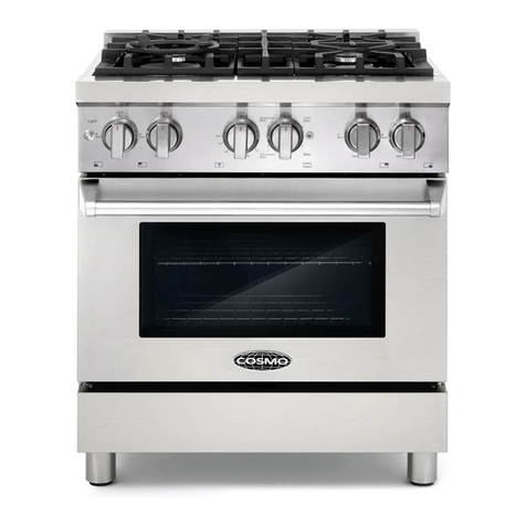
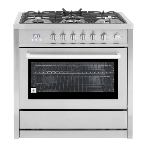
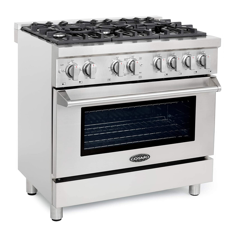
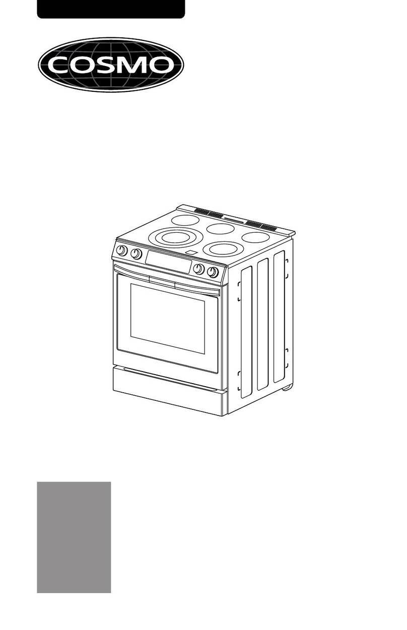
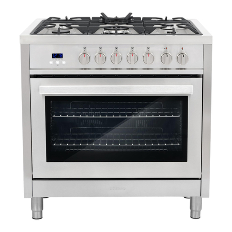
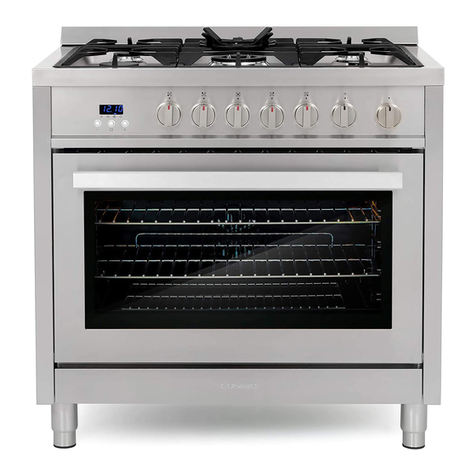
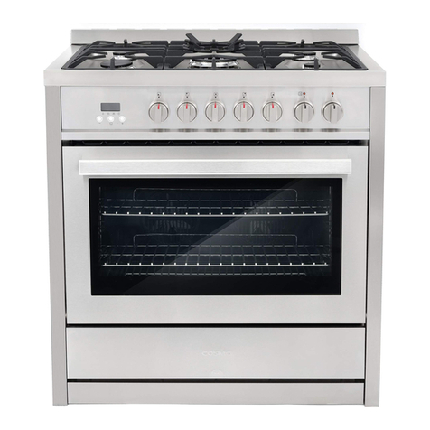
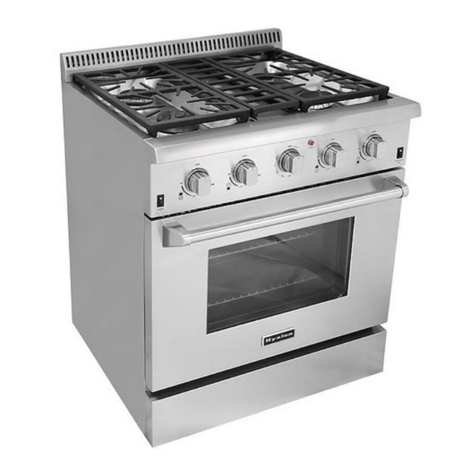
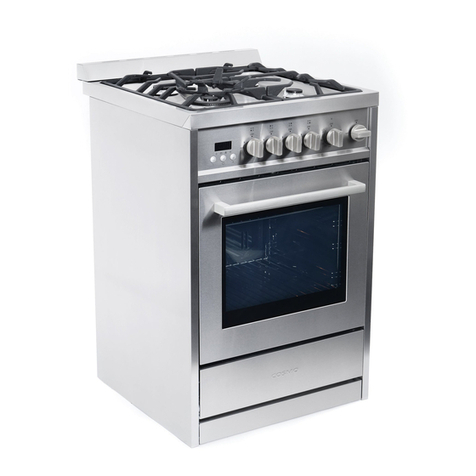
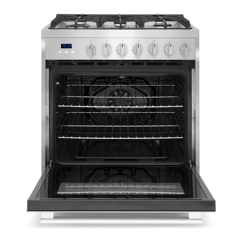
Cosmo COS-305AEC User manual

Installation Instructions
30 IN. ELECTRIC FREE- STANDING RANGE
CUISINIÈRE ÉLECTRIQUE AUTOPORTANTE DE 30 PO
COS-305AEC
INSTRUCTIONS D’INSTALLATION
I N S P I R I N G T H E W O R L D ’ S K I T C H E N
IMPORTANT SAFETY INSTRUCTIONS
Carefully read the following Important information redarding installation
safety and maintenance. Keep these instruction for future reference.
Instructions d’installation

2 3
THANK YOU FOR YOUR PURCHASE.
Thank you for your purchase. We know that you have many brands and
products to choose from and we are honored to know that you have decided
to take one of our products into your home and hope that you enjoy it.
COSMO appliances are designed according to the strictest safety and performance
standard for the North American market. We follow the most advanced
manufacturing philosophy. Each appliance leaves the factory after thorough
quality inspection and testing. Our distributors and our service partners are
ready to answer any questions you may have regarding how to install, use and
care for your products. We hope that this manual will help you learn to use the
product in the safest and most effective manner .
If you have any questions or concerns, please contact the dealer from whom you
purchased it, or contact our Customer Support at:
1-888-784-3108.
Please read the important safety instructions before using our product for
your own safety and to reduce the risk of fire or electrical shock, etc.
Please keep this manual for future use.
THANK YOU
1
RANGE SAFETY.........................................................................................................
INSTALLATION REQUIREMENTS .............................................................................
Tools and Parts .........................................................................................................
Location Requirements .............................................................................................
Electrical Requirements - U.S.A. Only ......................................................................
Electrical Requirements - Canada Only ....................................................................
INSTALLATION INSTRUCTIONS ..............................................................................
Step 1 - Unpack Range ............................................................................................
Step 2 - Install Anti-Tip Bracket ...............................................................................
Step 3 - Make Electrical Connection........................................................................
Step 4 - Install Range ................................................................................................
Step 5 - Complete Installation .................................................................................
Table of Contents
INSTRUCTIONSD’INSTALLATION..............................................................25

4 5
2
Range Safety
Your safety and the safety of others are very important.
We have provided many important safety messages in this manual
and on your appliance. Always read and obey all safety messages.
DANGER
WARNING
CAUTION
This is the safety alert symbol.
This symbol alerts you to potential hazards that can
kill or hurt you and others. All safety messages will
follow the safety alert symbol and either the word
“DANGER,” “WARNING” or “CAUTION.”
These words mean:
An imminently hazardous situation. You
could be killed or seriously injured if
you don’t immediately follow instructions.
A potentially hazardous situation which, if
not avoided, could result
in death or serious bodily injury.
A potentially hazardous situation
which, if not avoided, may result
in moderate or minor injury.
All safety messages will tell you what the potential hazard is, tell
you how to reduce the chance of injury, and tell you what can
happen if the instructions are not followed.
Tip Over Hazard
WARNING
3
State of California Proposition 65 Warnings:
WARNING: This product contains one or more chemicals known to
the State of California to cause cancer.
WARNING: This product contains one or more chemicals known to
the State of California to cause birth defects or other reproductive
harm.
A child or adult can tip the range and be killed.
Connect anti-tip bracket to rear range foot.
Reconnect the anti-tip bracket, if the range is moved.
Failure to follow these instructions can result in death or serious
burns to children and adults.
Range Safety

6 7
4
TOOLS AND PARTS
Gather the required tools and parts before starting installation. Read and follow
the instructions provided with any tools listed here.
TOOLS NEEDED
•Tape Measure
•Flat-Blade Screwdriver
•Phillips Screwdriver
•Level
•Cordless Electric Drill
•Hammer
•Wrench or Pliers
•Metal Saw
•Metal Snips or Large Wire Cutters
•15/N6" Combination Wrench
•3/8" Nut Driver
•1/4" Nut Driver
•1/8" (3.2 mm) Drill Bit (for wood floors)
•Marker or Pencil
•Masking Tape
PARTS SUPPLIED
Check that all parts are included.
a 16 x 1 5/8" Screws (2)
b Anti-tip Bracket
NOTE: The Anti-tip bracket must be securely mounted to the subfloor.
The thickness of flooring may require longer screws to anchor bracket to
subfloor. Longer screws are available from your local hardware store.
PARTS NEEDED
If using a power supply cord:
•A UL listed power supply cord kit marked for use with ranges. The cord should
be rated at 250 volts minimum, 40 amps or 50 amps that is marked for
use with nominal 13/8" (3.5 cm) diameter connection opening and must
end in ring terminals or open-end spade terminals with upturned ends.
•A UL listed strain relief.
If direct wiring:
•Flexible Metal Conduit
•UL Listed Conduit Connector
•4- ire or 3- ire Electrical Cable (where local codes permit a 3-wire connection).
•UL Listed Wire Connectors
Check local codes. Check existing electrical supply. See the appropriate
“Electrical Requirements” section. It is recommended that all electrical
connections be made by a licensed, qualified electrical installer.
Installation Requirements
5
LOCATION REQUIREMENTS
VENTILATION
IMPORTANT: Observe all governing codes and ordinances.
•It is the installer’s responsibility to comply with installation clearances, if
specified, on the model/serial rating plate. The model/serial rating plate is
located on the left-hand side of the oven frame. Open oven door to view
label. See label on back panel of range for additional element and oven
power ratings.
a
a Rating Plate
TEMPERATURE
IMPORTANT: Some cabinet and building materials are not designed to
withstand the heat produced by the oven for baking and self-cleaning. Check
with your builder or cabinet supplier to make sure that the materials used will
not discolor, delaminate or sustain other damage.
•Contact a qualified floor covering installer to check that the floor covering
can withstand at least 200°F (93°C).
•Use an insulated pad or 1/4" (0.64 cm) plywood under range if installing
range over carpeting.
GENERAL
•The range should be located for convenient use in the kitchen.
•Recessed installations must provide complete enclosure of the sides and
rear of the range.
•To eliminate the risk of burns or fire by reaching over heated surface units,
cabinet storage space located above the surface units should be avoided. If
cabinet storage is to be provided, the risk can be reduced by installing a
range hood or microwave hood combination that projects horizontally a
minimum of 5" (12.7 cm) beyond the bottom of the cabinets.
•All openings in the wall or floor where range is to be installed must be sealed.
•Do not seal the range to the side cabinets.
•Grounded electrical supply is required. See “Electrical Requirements” section.
Installation Requirements

8 9
6
DIMENSIONS
PRODUCT/OPENING
Opening dimensions shown are for 25" (64 cm) countertop depth, 24" (61 cm)
base cabinet depth and 36" (91.4 cm) countertop height.
Min. 24" (60.9 cm)
Max. 30" (77 cm)
a
5.9" (15 cm)
Min.
b
c
ed
Dimension
a 30" (76 cm)
b 29 7/8" (76 cm)
c 25" (63.5 cm)
d 36" (91.4 cm)
e 37 3/4" (96 cm)
NOTE: Range can be raised approximately 1" (2.5 cm) by adjusting the leveling
legs. Front of door and drawer may extend farther forward depending on styling.
BACK OF RANGE
a
b
c
a Access Panel to Electrical
Supply Connection
b Power Cord Opening
c Recessed Area
Installation Requirements
7
POWER SUPPLY
IMPORTANT: To connect to an outlet in the wall, the electrical outlet must be
recessed. If the electrical outlet is in the floor, it can be either recessed or
surface mounted.
a
b
d
ce
a 30" (76 cm)
b 171/2" (44 cm)
c 71/4" (18.4 cm)
d 3" (7.6 cm)
e Recommended
Location for
Electrical Outlet
ELECTRICAL REQUIREMENTS
IMPORTANT: This appliance is manufactured with the chassis connected to the
neutral by a green ground jumper wire. Use a 3-wire, UL listed, 50-amp power
supply cord (pigtail); or if local codes do not permit ground through the neutral,
use a 4-wire power supply cord rated at 250 volts, 50 amps and intended for
use with ranges. The ground must be revised so the green ground wire of the 4-
wire power supply is connected to the chassis. See “4-Wire Connection: “Power
Supply Cord” and “Direct Wire - U.S.A. Only” “4-Wire Connection (Ungrounded
Neutral)” sections.
If codes permit and a separate ground wire is used, it is recommended that
a qualified electrical installer determine that the ground path is adequate
and wire gauge is in accordance with local codes.
To properly install your range, you must determine the type of electrical
connection you will be using and follow the instructions provided for it here.
•Range must be connected to the proper electrical voltage and frequency as
specified on the model/serial number rating plate. All models are dual rated,
and designed to be connected to either 120/208 or 120/240V AC, 60Hz, 3-
wire or 4-wire, single-phase power supply.
Voltage and
Frequency Amps Circuit Required
240V, 60 Hz 50 A 50 Amp Circuit
208V, 60 Hz 43 A 45 Amp Circuit
•When a 4-wire, single phase 120/240 volt, 60 Hz., AC only electrical
supply is available, a 50-amp maximum circuit protection is required (or, if
specified on the model/serial rating plate, when a 4-wire, single phase
120/208 volt 60 Hz., AC only electrical supply is available, a 45-amp
maximum circuit protection is required).
Installation Requirements

10 11
Electrical Shock Hazard
WARNING
8
•For direct wire installations, install a suitable conduit box (not furnished).
An appropriately sized, UL conduit connector must be used to correctly
attach the conduit to the junction box.
IMPORTANT: Local Codes may vary; installation electrical connections
and grounding must comply with all applicable local codes.
ELECTRICAL REQUIREMENTS - U.S.A. ONLY
Do not use an extension cord.
Be sure that the electrical connection and wire size are adequate and in
conformance with the National Electrical Code, ANSI/ NFPA No. 70-latest
edition and all local codes and ordinances.
A copy of the above code standards can be obtained from:
National Fire Protection
Association One Batterymarch
Park
Quincy, MA 02269
The electrical power to the oven branch circuit must be shut off
while line connections are being made.
Do not use an extension cord with this appliance.
Electrical ground is required on this appliance. The free end of the
green wire (the ground wire) must be connected to a suitable
ground. This wire must remain grounded to the oven.
If cold water pipe is interrupted by plastic, non metallic gaskets,
union connections or other insulating materials, DO NOT use for
grounding.
DO NOT ground to a gas pipe.
DO NOT have a fuse in the NEUTRAL or GROUNDING circuit. A
fuse in the NEUTRAL or GROUNDING circuit could result in an
electrical shock.
Check with a qualified electrician if you are in doubt as to whether
the appliance is properly grounded.
Failure to do so could result in death, fire or electric shock.
The range is not equipped with a power cord. The range can be fitted with a 3 or
4-wire NEMA 14-50 or 10-50 type SRDT or ST (as required) power cord rated at
250 volt AC minimum, 50 amp, with 3 open-end spade lug connectors with
upturned ends or closed loop connectors and marked for use with ranges.
•A UL listed strain relief must be attached to the range to hold the power cord.
Installation Requirements
9
•Do not use an aluminum wire receptacle with copper-wired power cord and
plug (or vice versa). The proper wiring and receptacle is a copper-wired
power cord with a copper-wired receptacle.
•The electrical outlet should be located so that the power cord is accessible
when the range is in the installed position.
ELECTRICAL REQUIREMENTS - CANADA ONLY
Disconnect power before servicing.
Plug into a grounded outlet.
Do not use an extension cord.
Failure to do so can result in death, fire, or electrical shock.
If codes permit and a separate ground wire is used, it is recommended that
a qualified electrical installer determine that the ground path is adequate
and wire gauge are in accordance with local codes.
Be sure that the electrical connection and wire size are adequate and in
conformance with CSA Standard C22.1, Canadian Electrical Code, Part 1 -
latest edition, and all local codes and ordinances.
A copy of the above code standards can be obtained from:
Canadian Standards
Association 178 Rexdale Blvd.
Toronto, ON M9W 1R3
CANADA
•Check with a qualified electrical installer if you are not sure the range is
properly grounded.
•This range is equipped with a CSA International Certified Power Cord
intended to be plugged into a standard 14-50R wall receptacle. Be sure the
wall receptacle is within reach of range’s final location.
•Do not use an extension cord.
Installation Requirements
Electrical Shock Hazard
WARNING

12 13
Excessive Weight Hazard
WARNING
10
IMPORTANT: This appliance shall be installed only by authorized persons and in
accordance with the manufacturer’s installation instructions, local gas fitting
regulations, municipal building codes, electrical wiring regulations, local water
supply regulations.
STEP 1 - UNPACK RANGE
Use two or more people to move and install range.
Failure to do so can result in back or other injury.
1. Remove shipping materials, tape and film from the range. Keep
cardboard bottom under range. Do not dispose of anything until the
installation is complete.
2. Remove oven racks and parts package from oven and shipping materials.
3. To remove cardboard bottom, first take four cardboard corners from the
carton. Stack one cardboard corner on top of another. Repeat with the
other two corners. Place them lengthwise on the floor behind the range to
support the range when it is laid on its back.
4. Using two or more people, firmly grasp the range and gently lay it on its
back on the cardboard corners.
5. Remove cardboard bottom.
NOTES:
•The leveling legs can be adjusted while the range is on its back.
•To place range back up into a standing position, put a sheet of
cardboard or hardboard on the floor in front of range to protect the
flooring. Using two or more people, stand range back up onto the
cardboard or hardboard.
Installation Instructions
WARNING
Tip Over Hazard
11
STEP 2 - INSTALL ANTI-TIP BRACKET
A child or adult can tip the range and be killed.
Connect anti-tip bracket to rear range foot.
Reconnect the anti-tip bracket, if the range is moved.
Failure to follow these instructions can result in death or serious
burns to children and adults.
IMPORTANT: An anti-tip bracket kit is included with the range. The anti-tip bracket
uses either the right or left rear leveling leg to secure the range to the floor.
1. Remove the anti-tip bracket from where it is taped inside the oven or storage
drawer.
2. Determine and mark centerline of the opening.
NOTE: The anti-tip bracket can be installed on either the left-hand side or
right-hand side of the opening.
3. Place the anti-tip bracket onto the floor so that the distances from the center
of the bracket to the centerline and from the center of the bracket to the wall
are as follows:
•Center of Opening to Center of Bracket: 131/2" (34.3 cm)
•Wall to Top of Bracket - 35/A6" (8. cm)
4. Drill two 1/8" (3 mm) holes through the mounting holes in the anti-tip
bracket and into the floor.
NOTE: Contact a qualified floor covering installer for the best procedure
for drilling mounting holes through your type of floor covering.
5. Using the two screws provided, secure the anti-tip bracket to the floor.
NOTE: A rear leg of the range will be centered within the anti-tip bracket
when it is moved into its final position.
Installation Instructions

14 15
WARNING
Electrical Shock Hazard
12
STEP 3 - MAKE ELECTRICAL CONNECTION
After reading the requirements for each Electrical Connection method, follow
the instructions specific to your situation.
POWER CORD - U.S.A. ONLY
Disconnect power before servicing.
Use a new 50 amp UL listed or CSA certified power supply
cord. Plug into a grounded outlet.
Do not use an extension cord.
Failure to do so can result in death, fire, or electrical shock.
3-WIRE CONNECTION: POWER SUPPLY CORD
IMPORTANT: Use this method only if local codes permit connecting chassis
ground conductor to neutral wire of power supply cord.
1. Disconnect power.
2. Remove the access panel located on the bottom right-hand side of the
back panel to uncover the electrical terminal block.
a
b
c
a Access Panel to Electrical
Supply Connection
b Power Cord Opening
c Recessed Area
Installation Instructions
13
3. Install a UL listed strain relief (not provided) to the power cord opening in
the bracket, and then completely tighten the strain relief nut.
4. Thread the end of the power cord through the strain relief.
NOTE: Allow enough slack to connect the wires to the terminal
block.
c
a UL Listed Strain Relief
a
b Power Cord
b
c Jumper Wire
5. Using a 5/16" nut driver and one of the -0-32 hex nuts, connect the neutral
(white) wire from the power cord to the center terminal block post along with
the green jumper wire from the range.
6. Using 10-32 hex nuts, connect the red and black wires from the power cord
to the outer posts of the terminal block with the corresponding red and
black wires from the range.
7. Tighten the hex nuts completely, and then verify the connection.
NOTE: For power supply cord replacement, use only a power cord rated
at 250volts minimum, 50-amps that is marked for use with nominal 1 3/8"
(3.5cm) diameter connection opening, with ring terminals and marked for
use with ranges.
8. Position the lower part of the strain relief under the power cord and tighten
the strain relief screws.
NOTE: Before tightening, make sure the strain relief is positioned over the
cord and NOT the wires.
9. Replace the electrical access panel.
10. Plug range into grounded outlet.
11. Tuck excess power cord into the recessed area of the back panel.
Installation Instructions

16 17
14
4-WIRE CONNECTION: POWER SUPPLY CORD
IMPORTANT: Use this method for new branch-circuit installations (1996
NEC), mobile homes, recreational vehicles, or in an area where local codes
prohibit grounding through the neutral.
1. Disconnect power.
2. Remove the access panel located on the bottom right-hand side of the
back panel to expose the electrical terminal block.
a
b
c
a Access Panel to Electrical
Supply Connection
b Power Cord Opening
c Recessed Area
3. Install a UL listed strain relief to the power cord opening in the support
bracket, and fully tighten the strain relief nut.
4. Feed the power supply cord through the strain relief. Allow enough slack to
easily attach the wiring to the terminal block.
a
bde
c
a Ground Screw
b Terminal Block
c Jumper Wire
d Power Cord Wires
e UL Listed Strain Relief
Installation Instructions
WARNING
Electrical Shock Hazard
15
5. Remove the green jumper wire from under the ground screw and replace
with the green wire from the power cord and tighten ground screw.
6. Loop the green jumper wire removed from the ground screw back onto its
end that is fastened to the center post on the terminal block.
7. Use 5/16" nut driver to connect the neutral (white) wire to the center
terminal block post with one of the 10-32 hex nuts.
8. Using 10-32 hex nuts, connect the red and black wires from the power cord
to the outer posts of the terminal block with the corresponding red and
black wires from the range.
9. Tighten the hex nuts completely, and then verify the connection.
NOTE: For power supply cord replacement, use only a power cord rated
at 2.0volts minimum, .0-amps that is marked for use with nominal
3/8" (3..cm) diameter connection opening, with ring terminals and
marked for use with ranges.
10. Position the lower part of the strain relief under the power cord and
tighten the strain relief screws.
NOTE: Before tightening, make sure the strain relief is positioned over the
cord and NOT the wires.
11. Replace the electrical access panel.
12. Plug range into grounded outlet.
13. Tuck excess power cord into the recessed area of the back panel.
POWER CORD - CANADA ONLY
Plug into a grounded outlet.
Do not use an extension cord.
Failure to do so can result in death, fire, or electrical shock.
1. Plug into a standard 14-50R grounded wall receptacle.
2. Go to STEP 4 - INSTALL RANGE.
Installation Instructions

18 19
WARNING
Electrical Shock Hazard
16
DIRECT WIRE - U.S.A. ONLY
Disconnect power before servicing.
Improper connection of aluminum house wiring and copper
appliance leads can result in an electrical hazard or fire. If the home
has aluminum wiring, only use connectors designed and UL listed
for joining copper to aluminum and precisely follow the
manufacturer's recommended procedure. Aluminum-to-Copper
connections must conform with local codes.
Use 8 gauge copper or 6 gauge aluminum wire.
Electrically ground range.
Failure to do so can result in death, fire or electrical shock.
Be sure your appliance is properly installed and grounded by a qualified
technician. Ask your dealer to recommend a qualified technician or an
authorized repair service.
•A circuit breaker is recommended.
•The range can be connected directly to the circuit breaker box (or fused
disconnect) through flexible or nonmetallic sheathed, copper or aluminum
cable.
•Allow at least 6 ft (1.8 m) of slack in the line so that the range can be
moved if servicing is ever necessary.
•A UL listed conduit connector must be provided at each end of the power
supply cable (at the range and at the junction box).
•Wire sizes and connections must conform with the rating of the range.
•The tech sheet and wiring diagram are included with the range.
This appliance is manufactured with the chassis connected to the neutral by a
green ground jumper wire. After making sure that the power has been turned
off, connect the flexible conduit from the oven to the junction box using a UL
listed conduit connector. The Grounded Neutral and Ungrounded Neutral
Graphics on the following pages and the instructions provided, present the
most common way of connecting the ovens. Your local codes and ordinances,
of course, take precedence over these instructions. Complete electrical
connections according to local codes and ordinances.
Installation Instructions
WARNING
Electrical Shock Hazard
17
3-WIRE CONNECTION (GROUNDED NEUTRAL)
Grounding through the neutral conductor is prohibited for new
branch-circuit installations (1996 NEC); mobile homes; and
recreational vehicles, or in an area where local codes prohibit
grounding through the neutral conductor. For installations where
grounding through the neutral conductor is prohibited, see the
Ungrounded Neutral graphic.
Use grounding terminal or lead to ground unit.
Connect neutral terminal or lead to branch circuit neutral in
usual manner.
Failure to do so could result in death, fire or electric shock.
Connect to the House Electrical Supply
IMPORTANT: Use the 3-wire cable from home power supply where local
codes permit a 3-wire connection.
1. Disconnect power.
Grounded Neutral
a
b
c
d
g
h
f
e
i
a Junction Box
b Black Wires
c Neutral (White)
Wire
d Ground (Green or
Bare) Wire
e Cable from Range
f UL Listed Conduit
Connector
g Red Wires
h UL Listed Wire Connectors
i House Electrical Supply
2. Connect the 2 black wires btogether using a UL listed wire connector.
Installation Instructions

20 21
18
3. Connect the neutral (white) wire c and the ground (green or bare) wire d (of
the range cable) using a UL listed wire connector.
4. Connect the 2 red wires gtogether using a UL listed wire connector.
5. Install junction box cover.
Connect to the Range
IMPORTANT: Use this method only if local codes permit connecting chassis
ground conductor to neutral wire of power supply cord.
1. Feed the electric cable wires through the flexible metal conduit.
NOTE: Allow enough slack to easily attach the wires to the terminal block.
2. Remove the access panel located on the bottom right-hand side of the
back panel to uncover the electrical terminal block.
b
a
c
a Electrical Access Panel
b Conduit Opening
c Recessed Area
3. Install a UL listed strain relief (not provided) to the conduit opening in
the bracket, and then completely tighten the strain relief nut.
4. Thread the end of the conduit through the strain relief.
NOTE: Allow enough slack to connect the wires to the terminal
block.
bc
a
a Jumper Wire b UL Listed Strain Relief c Conduit
Installation Instructions
19
5. Using a 5/16" nut driver and one of the l0-32 hex nuts, connect the ground
(green or bare) wire from the flexible metal conduit to the center terminal
block post along with the green jumper wire from the range.
6. Using 10-32 hex nuts, connect the red and black wires from the power cord
to the outer posts of the terminal block with the corresponding red and
black wires from the range.
7. Tighten the hex nuts completely, and then verify the connection.
8. Position the lower part of the strain relief under the flexible metal conduit
and tighten the strain relief screws.
NOTE: Before tightening, make sure the strain relief is positioned over
the flexible metal conduit and NOT the wires.
9. Replace the electrical access panel.
10. Tuck excess conduit into the recessed area of the back panel.
4-WIRE CONNECTION (UNGROUNDED NEUTRAL)
Connect to the House Electrical Supply - U.S.A. Only
IMPORTANT: Use the 4-wire cable from home power supply in the U.S. where
local codes do not allow grounding through neutral, new branch circuit
installations (l99e NEC), mobile homes and recreational vehicles, new
construction and in Canada. Ungrounded Neutral
i
b
c
d
g
f
e
h
a
a Junction Box
b Black Wires
c Red Wires
d Cable from Range
e UL listed or CSA
Approved Conduit
Connector
f Ground (Green or
Bare) Wires
g UL Listed Wire
Connector
h Neutral (White) Wires
i House Electrical Supply
1.Connect the 2 black wires btogether using a UL listed wire connector.
2. Connect the 2 red wires ctogether using a UL listed wire connector.
3. Connect the 2 neutral (white) wires htogether using a UL listed wire connector.
4.Connect the ground (green or bare) wire ffrom the range cable to the ground
(green or bare) wire (in the junction box) using a UL listed wire connector.
5. Install junction box cover.
Installation Instructions

22 23
20
Connect to the Range
IMPORTANT: Use this method for new branch-circuit installations (1996
NEC), mobile homes, recreational vehicles, or in an area where local codes
prohibit grounding through the neutral.
1. Feed the electric cable wires through the flexible metal conduit.
NOTE: Allow enough slack to easily attach the wires to the terminal block.
2. Remove the access panel located on the bottom right-hand side of the
back panel to expose the electrical terminal block.
b
a
c
a Electrical Access Panel
b Conduit Opening
c Recessed Area
3. Install a UL listed strain relief to the flexible metal conduit opening in the
support bracket, and fully tighten the strain relief nut.
4. Feed the flexible metal conduit through the strain relief. Allow enough
slack to easily attach the wiring to the terminal block.
a
bd
c
a Ground Screw
b Terminal Block
c Jumper Wire
e
d Electrical Cable Wires
e UL Listed Strain Relief
5. Remove the green jumper wire from under the ground screw and replace with
the green wire from the flexible metal conduit and tighten ground screw.
Installation Instructions
21
9. Tighten the hex nuts completely, and then verify the connection.
10. Position the lower part of the strain relief under the flexible metal conduit
and tighten the strain relief screws.
NOTE: Before tightening, make sure the strain relief is positioned over
the flexible metal conduit and NOT the wires.
11. Replace the electrical access panel.
12. Tuck excess conduit into the recessed area of the back panel.
STEP 4 - INSTALL RANGE
IMPORTANT: If the range is moved to adjust the leveling legs, make sure
when you move the range back into its final location that the anti-tip bracket is
engaged by repeating steps 1 through 9.
1. Slide range into final location, making sure rear leveling leg slides into anti-
tip bracket. Leave a l" (2.e cm) gap between the back of the range and the
back wall.
2. Place the outside of your foot against the bottom front to keep the range
from moving, and then grasp the back of the range, as shown.
3. Slowly attempt to tilt the range forward.
If you encounter immediate resistance, the range foot is engaged in the
anti-tip bracket. Go to Step 8.
4. If the rear of the range lifts more than 1/2" (l.3 cm) off the floor without
resistance, stop tilting the range and lower it gently back to the floor. The
range foot is not engaged in the anti-tip bracket.
Installation Instructions
IMPORTANT: If there is a snapping or popping sound when lifting the range,
the range may not be fully engaged in the bracket. Check to see if there are
obstructions keeping the range from sliding to the wall or keeping the range
foot from sliding into the bracket. Verify that the bracket is held securely in
place by the mounting screws.
6. Loop the green jumper wire removed from the ground screw back onto its
end that is fastened to the center post on the terminal block.
7. Use 5/16" nut driver to connect the neutral (white) wire to the center
terminal block post with one of the 10-32 hex nuts.
8. Using 10-32 hex nuts, connect the red and black wires from the power cord
to the outer posts of the terminal block with the corresponding red and
black wires from the range.
5. Slide the range forward, and verify that the anti-tip bracket is securely
attached to the floor or wall.
6. Slide range back so the rear range foot is inserted into the slot of the
anti-tip bracket.
7. Repeat steps 1 through 3 to ensure that the range foot is engaged in the
anti-tip bracket.
If the rear of the range lifts more than 1/2" (l.3 cm) off the floor without
resistance, the anti-tip bracket may not be installed correctly. Do not
operate the range without anti-tip bracket installed and engaged.

24
22
8. Move the range into its final location. Check that the range is level by placing a
level on the oven bottom.
NOTE: The range must be level for optimum cooking and baking performance.
9. If needed, use a wrench to adjust the height of the leveling legs until the
range is level from side to side and front to back.
Circuit Diagram
1. Reconnect power at the circuit breaker or fuse box.
2. Turn on each element to check that it is heating correctly.
3. Turn on the oven to check that it is heating correctly.
NOTE: When the range has been on for 5 minutes, check for heat. If range is
cold, turn off the range and contact a qualified technician.
4. Check that the indicator lights on the control panel, and the interior oven
lights illuminate correctly.
If the range does not operate correctly, check the following:
•Household fuse is intact and tight; or circuit breaker has not tripped.
•Range is plugged into a grounded outlet.
•Electrical supply is connected.
Contact a qualified electrician to verify the electrical supply.
Installation Instructions
STEP 5 - COMPLETE INSTALLATION
1
2
2a
1a
P2 P1
SCER
S2 2
4 4b
S1
Pilot
P2 P1
SCER
S1
Pilot
4 S2 2
P2 P1
SCER
S1
Pilot
4 S2 2
4a 4a
H S
SCHE
2
4
H S
SCHE
2
4
H S
SCHE
2
4
H S
SCHE
2
4
4a
4a
4b
P1
HIL
HIL
HIL
HIL
HIL
PCB BOARD
PCB BOARD
DISPLAY
Top GrillBack g rill Bottom G rill
85 T hermal cut off
110 Thermal cut off
L1(RED)
L2(BLACK)
N(WHITE)
G(GREEN)
UP_HT_CUT
A68
A67
A65
A66
A42
A10
A43
A12
A52
A53
A54
A55
L1
L2
L2
L1
L2
L1
Cyc
fan Lamp
Low
Cool fan
High
Cool fan Latch
M1M2M3M4
Probe
GND
Baffle
GND
GND
Probe
probe_downprobe_up
Baffle
TO_SWPOWER
TO_DISP
LN
B Plug
DOOR
Latch1
Latch2
GND
DOOR
Latch1
Latch2
GND
A Plug
Probe socket
down sensor up sensor
Latch_door2 Latch_door1
CUISINIÈRE ÉLECTRIQUE
AUTOPORTANTE DE 30 PO
COS-305AEC
INSTRUCTIONS D’INSTALLATION
INSTRUCTIONS IMPORTANTES DE SÉGURITÉ
Lire attentivement l'importante information concernant la sécurité l'installation
et l'entretien. Conserver ces instructions pour référence future.

26 27
23
SÉCURITÉ DE LA CUISINIÈRE ................................................................................ 24
EXIGENCES D’INSTALLATION ................................................................................ 25
Outillage et pièces ...................................................................................................25
Exigences d’emplacement .......................................................................................27
Exigences électriques ..............................................................................................30
INSTRUCTIONS D’INSTALLATION .......................................................................... 33
Étape 1 - Déballage de la cuisinière ........................................................................33
Étape 2 - Installation de la bride antibasculement ...................................................34
Étape 3 - Raccordement électrique ..........................................................................35
Étape 4 - Installation de la cuisinière .......................................................................46
Étape 5 – Fin de l’installation ..................................................................................47
Table des Matières
24
Sécurité de la Cuisinière
Votre sécurité et celle des autres est très importante.
DANGER
AVERTISSEMENT
ATTENTION
Voici le symbole d’alerte de sécurité.
Ce symbole d’alerte de sécurité vous signale les
dangers potentiels de décès et de blessures graves
à vous et à d’autres. Tous les messages de sécurité
suivront le symbole d’alerte de sécurité et le mot
“DANGER”, “AVERTISSEMENT” ou “ATTENTION”.
Ces mots signifient :
Une situation de danger
imminent. Vous courez le risque
d’un décès ou de blessures
graves si vous ne suivez pas
immédiatement les instructions.
Une situation potentiellement
dangereuse qui, si vous ne
l’évitez pas, peut provoquer la
mort ou des blessures graves.
Une situation potentiellement
dangereuse qui, si vous ne
l’évitez pas, peut entraîner des
blessures légères à modérées.
Tous les messages de sécurité vous diront quel est le danger
potentiel et comment réduire le risque de blessure et ce qui peut
se produire en cas de non-respect des instructions.
Nous donnons de nombreux messages de sécurité importants
dans ce manuel et sur votre appareil ménager. Assurez-vous de
toujours lire tous les messages de sécurité et de vous y conformer.
27
28
28
30
33
36
36
37
38
49
50

28 29
AVERTISSEMENT
Risque de basculement
25
Un enfant ou une personne adulte peut faire basculer la cuisinière
ce qui peut causer un décès.
Joindre la bride antibasculement au pied arrière de la cuisinière.
Joindre de nouveau la bride antibasculement si la cuisinière
est déplacée.
Le non-respect de ces instructions peut causer un décès ou
des brûlures graves aux enfants et aux adultes.
OUTILLAGE ET PIÈCES
Rassembler les outils et composants nécessaires avant d’entreprendre
l’installation. Lire et observer les instructions fournies avec chacun des outils de
la liste ci-dessous.
OUTILS NÉCESSAIRES
•Mètre enrouleur
•Tournevis à lame plate
•Tournevis Phillips
•Niveau
•Perceuse électrique sans fil
•Marteau
•Clé ou pince
•Scie à métaux
•Cisaille de ferblantier ou coupe-
fils de grande taille
•Clé mixte de isque"
•Tourne-écrou de 3/8"
•Tourne-écrou de 1/4"
•Foret de 1/8" (3,2 mm) (pour
planchers en bois)
•Marqueur ou crayon
•Ruban adhésif de masquage
Sécurité de la Cuisinière
Exigences d'installation
26
PIÈCES FOURNIES
Vérifier que toutes les pièces sont présentes.
a Vis de 16 x 1 5/8" (2)
b La bride antibasculement
REMARQUE : Les brides antibasculement doivent être solidement fixées
au sous-plancher. La profondeur du plancher peut nécessiter des vis plus
longues pour l’ancrage de la bride dans le sous-plancher. Des vis plus
longues sont disponibles auprès de votre quincaillerie locale.
PIÈCES NÉCESSAIRES
En cas d’utilisation d’un cordon d’alimentation électrique :
•Un cordon d’alimentation (homologation UL) conçu pour utilisation avec des
cuisinières. Pour service 250 volts minimum, 40 A ou 50 A, compatible
avec une ouverture de diamètre nominal 13/8” (3,5 cm) pour le
raccordement, et avec cosses rondes ou en fourche à pointes relevées à
l’extrémité de chaque conducteur.
•Un serre-câble (homologation UL).
En cas de raccordement par câblage direct :
•Conduit métallique flexible
•Connecteur de conduit (homologation UL)
•Câble électrique à 4 ou 3 conducteurs (là où les codes locaux
autorisent un raccordement à un câble à 3 conducteurs).
•Connecteurs de fils (homologation UL)
Consulter les codes locaux. Vérifier l’alimentation électrique existante. Voir
la section “Spécifications électriques” correspondante. Il est recommandé
de faire réaliser tous les raccordements électriques par un électricien qualifié
agréé.
Exigences d'installation

30 31
27
EXIGENCES D’EMPLACEMENT
VENTILATION
IMPORTANT : Respecter les dispositions de tous les codes et réglements en
vigueur.
•C’est à l’installateur qu’incombe la responsabilité de respecter les distances
de séparation indiquées sur la plaque signalétique si spécifié. La plaque
signalétique est située du côté gauche du cadre du four. L’étiquette est
visible en ouvrant la porte du four. Consulter l’étiquette située sur le panneau
arrière de la cuisinière pour obtenir des informations supplémentaires et
connaître la puissance nominale du four.
a
a Plaque signalétique
TEMPÉRATURE
IMPORTANT : Les matériaux de certains placards et certains matériaux de
construction ne sont pas conçus pour résister à la chaleur générée par le four
durant la cuisson au four ou l’autonettoyage. Consulter le constructeur de la
maison ou le fabricant des placards pour déterminer si les matériaux utilisés
pourraient subir un changement de couleur, une déstratification ou d’autres
dommages.
•Contacter un installateur de revêtement de sol qualifié, qui pourra déterminer si
le revêtement de sol peut résister à une température d’au moins 200 °F (93 °C).
•Dans le cas de l’installation de la cuisinière par dessus un tapis, placer sous
la cuisinière une plaque d’appui isolée, ou une plaque de contreplaqué de
1/4" (0,64 cm).
RENSEIGNEMENTS GÉNÉRAUX
•La cuisinière doit être placée de manière à permettre une utilisation pratique
dans la cuisine.
•Dans le cas d’une cuisinière encastrée, l’enceinte doit recouvrir
complètement les côtés et l’arrière de la cuisinière.
•Afin de minimiser le risque de brûlures ou d’incendie au-dessus de la table
de cuisson, on doit éviter d’installer un placard mural. Si le rangement en
placard est envisagé, le risque peut être réduit par l’installation d’une hotte
de cuisinière ou un ensemble hotte/micro-ondes opérant horizontalement
sur un minimum de 5" (12,7 cm) au-delà du bas des placards.
•Toutes les ouvertures dans le mur ou le plancher de l’emplacement
d’installation de la cuisinière doivent être scellées.
•Ne pas réaliser un scellement entre la cuisinière et les placards latéraux.
•Une source d’électricité avec liaison à la terre est nécessaire. Voir la
section “Spécifications électriques”.
Exigences d'installation
28
DIMENSIONS
PRODUIT/OUVERTURE
Les dimensions de l’ouverture correspondent à une installation entre des
placards de 24” (61 cm) de profondeur, avec plan de travail de 25” (64 cm) de
profondeur et de 36” (91,4 cm) de hauteur.
a
5,9" (15 cm)
Min.
b
c
ed
Dimension
a 30" (76 cm)
b 297/8" (76 cm)
c 25" (63,5 cm)
d 36" (91,4 cm)
e 37 3/4" (96 cm)
REMARQUE : La cuisinière peut être surélevée d’environ 1” (2,5 cm) en
ajustant les pieds de nivellement. L’avant de la porte et du tiroir peuvent
s’avancer davantage en fonction de l’agencement souhaité.
Exigences d'installation
Min. 24" (60,9 cm)
Max. 30" (77 cm)

32 33
29
Arrière de la cuisinière
a
b
c
a Panneau d’accès
au raccordement à
l’alimentation électrique
b Ouverture du cordon
d’alimentation
c Encastrement
ALIMENTATION ÉLECTRIQUE
IMPORTANT : Pour un raccordement à une prise murale, la prise électrique doit
être encastrée. Si la prise électrique se trouve au sol, elle peut être soit
encastrée, soit montée en surface.
a
b
d
ce
a 30" (76 cm)
b 171/2" (44 cm)
c 7 1/4" (18,4 cm)
d 3" (7,6 cm)
e Emplacement
recommandé
pour la prise
électrique
Exigences d'installation
30
EXIGENCES ÉLECTRIQUES
IMPORTANT : Cet appareil est fabriqué avec le châssis raccordé au neutre par
un cavalier vert de liaison à la terre. Utiliser un cordon d’alimentation à 3 fils,
homologué UL, un cordon d’alimenation de 50 ampères (queue de cochon); ou
si les codes locaux ne permettent pas la mise à la terre à travers le fil neutre,
utiliser un cordon d’alimentation à 4 fils spécifié pour une tension nominale de
250 volts, 50 ampères et approuvé pour une utilisation avec des cuisinières. Le
circuit de terre doit être modifié pour que le conducteur de terre vert du cordon
d’alimentation électrique
à 4 conducteurs soit raccordé au châssis. Voir les sections “Raccordement de la
connexion à 4 conducteurs : “Cordon d’alimentation électrique” et
“Raccordement direct - É.-U. uniquement” “Connexion à 4 conducteurs (neutre
non relié à la terre)”.
Si les codes locaux le permettent et un fil de terre séparé est utilisé, il est
recommandé qu’un électricien qualifié vérifie que le chemin de terre est
adéquat et que le calibre du fil de terre est conforme aux codes locaux.
Afin d’installer correctement votre cuisinière, vous devez déterminer le type de
connexion électrique que vous allez utiliser et suivre les instructions indiquées ici.
•La cuisinière doit être connectée à la tension électrique et fréquence
spécifiées sur le modèle / numéro de série de la plaque signalétique. Tous
les modèles sont conçus pour être raccordés soit à 208 / 240 VCA, 60 Hz,
3 fils ou soit à une alimentation, 4 fils.
Tension et
fréquence Ampères Circuit nécessaire
240V, 60 Hz 50 A 50 ampères
208V, 60 Hz 43 A 45 ampères
•Lorsqu’une source d’électricité monophasée de 120/240 volts, 60 Hz/4
conducteurs (CA uniquement) est disponible, le circuit doit comporter
un dispositif de protection de 50 A maximum (ou 45 A si la source
d’électricité spécifiée sur la plaque signalétique est de 120/208 volts).
•Pour un raccordement par câblage direct à l’aide d’un conduit,
l’alimentation électrique doit être un circuit CA biphasé à 3 ou 4
conducteurs. Installer une boîte de dérivation appropriée (non fournie).
Un connecteur de conduit homologué UL de dimension appropriée doit
être utilisé pour relier correctement le conduit à la boîte de connexion.
IMPORTANT : Les codes locaux peuvent varier; les raccordements
électriques d’installation et de mise à la terre doivent être conformes à tous
les codes locaux applicables.
EXIGENCES ÉLECTRIQUES - ÉTATS-UNIS UNIQUEMENT
Ne pas utiliser de câble de rallonge.
S’assurer que la connexion électrique et le calibre des fils sont appropriés et
en conformité avec le National Electrical Code, ANSI / NFPA n° 70 - dernière
édition et avec tous les codes et règlements locaux.
On peut obtenir un exemplaire de la norme ci-dessus auprès de :
National Fire Protection
Association One Batterymarch
Park
Quincy, MA 02269
Exigences d'installation

34 35
AVERTISSEMENT
Risque de choc électrique
31
L’alimentation électrique du circuit du branchement du four doit
être coupée lorsque les connexions des lignes sont mises en place.
Ne pas utiliser pas de rallonge avec cet appareil.
Une mise électrique à la terre est nécessaire pour cet appareil.
L’extrémité libre du connecteur vert (le connecteur de mise à la
terre) doit être connectée à la masse appropriée. Ce connecteur
doit rester branché à la masse au four.
Si un tuyau d’eau froide est interrompu par du plastique, des joints
non métalliques, des raccords union ou d’autres matériaux isolants,
NE PAS L'UTILISER pour la mise à la terre.
NE PAS brancher la masse à une canalisation de gaz.
Le circuit du NEUTRE ou de LIAISON A LA TERRE NE DOIT PAS
contenir de fusible. Un fusible dans le circuit du neutre ou de
liaison à la terre pourrait entraîner une électrocution.
L'utilisateur doit consulter un électricien quali−é s'il n'est pas sûr
que l'appareil est correctement relié à la terre.
Le non-respect de cette instruction peut causer un décès, un
incendie ou un choc électrique.
La cuisinière n’est pas équipée d’un cordon d’alimentation. La cuisinière peut
être équipée d’un cordon d’alimentation électrique à 3 ou 4 conducteurs
NEMA 14-50 ou 10-50 de type SRDT ou ST (comme nécessaire) de 250 VCA
minimum et 50 A, terminé par 3 cosses rondes ou en fourche à pointes
relevées et approuvé pour utilisation avec les cuisinières.
•Un serre-câble homologué UL doit être fixé à la cuisinière pour maintenir le
cordon d’alimentation.
•Ne pas utiliser de prise secteur à conducteurs en aluminium avec un
cordon et une fiche d’alimentation à conducteurs en cuivre (et
inversement). Le raccordement correct est un cordon à conducteurs en
cuivre et une prise secteur à conducteurs en cuivre.
•La prise secteur doit être située de telle sorte que le cordon d’alimentation
soit accessible lorsque la cuisinière est à son emplacement final.
Exigences d'installation
AVERTISSEMENT
Risque de choc électrique
32
EXIGENCES ÉLECTRIQUES - CANADA UNIQUEMENT
Déconnecter la source de courant électrique avant l'entretien.
Utilisez un nouveau cordon d'alimentation homologué
CSA International.
Brancher sur une prise de terre.
Ne pas utiliser de câble de rallonge.
Le non-respect de cette instruction pourrait causer un décès,
un incendie ou un choc électrique.
Si les codes en vigueur le permettent et qu’un conducteur distinct de liaison à
la terre est utilisé, on recommande qu’un électricien qualifié vérifie que la
liaison à la terre et la taille du conducteur de liaison à la terre sont adéquats et
conformes aux prescriptions des codes locaux.
Vérifier que le raccordement à la source d’électricité et le calibre des
conducteurs sont conformes aux prescriptions de la plus récente édition de la
norme CSA C22.1, partie 1 - Code canadien de l’électricité, et de tout code ou
règlement local en vigueur.
On peut obtenir un exemplaire de la norme ci-dessus auprès de :
Canadian Standards Association
178 Rexdale Blvd.
Toronto, ON M9W 1R3 CANADA
•En cas de doute quant à la qualité de la liaison à la terre de la cuisinière,
consulter un électricien qualifié.
•Cette cuisinière est dotée d’un cordon d’alimentation (homologation CSA
International) destiné à être branché sur une prise de courant murale
standard 14-50R. Veiller à ce que la prise de courant murale soit placée à
proximité de l’emplacement définitif de la cuisinière.
•Ne pas utiliser de câble de rallonge.
Exigences d'installation

36 37
33
IMPORTANT : Cet appareil doit être installé uniquement par des personnes
autorisées et en conformité avec les instructions d’installation du fabricant,
les règlements locaux en matière de raccordement au gaz, les codes du
bâtiment municipaux, les règlements spécifiques au câblage électrique, les
règlements d’approvisionnement en eau locaux.
ÉTAPE 1 - DÉBALLAGE DE LA CUISINIÈRE
Utiliser deux personnes ou plus pour déplacer et installer la
cuisinière.
Le non-respect de cette instruction peut causer une blessure au dos
ou d'autre blessure.
1. Ôter les matériaux d’emballage, le ruban adhésif et la pellicule protectrice
de la cuisinière. Garder la base de carton sous la cuisinière. Ne rien jeter
avant d’avoir complètement terminé l’installation.
2. Retirer les grilles de four et le sachet de pièces du four et les
matériaux d’emballage.
3. Pour retirer le fond en carton, prendre d’abord les 4 coins en carton de la
caisse. Empiler l’un des coins sur un autre. Répéter avec les 2 autres coins.
Les disposer sur le plancher dans le sens de la longueur derrière la
cuisinière, à titre de support de la cuisinière lorsque celle-ci est placée sur
sa partie postérieure.
4. À l’aide d’au moins deux personnes, saisir fermement la cuisinière et la
déposer délicatement sur sa partie postérieure, sur les coins de protection.
5. Retirer le fond en carton.
REMARQUES :
•Les pieds de nivellement peuvent être réglés pendant que la cuisinière repose
sur sa partie postérieure.
•Pour relever la cuisinière en position verticale, placer un carton ou un
panneau de fibres dur au sol devant la cuisinière pour protéger le plancher. À
deux personnes au moins, redresser la cuisinière et la placer sur le carton ou
le panneau de fibres dur.
Instructions d'installation

AVERTISSEMENT
Risque du poids excessif
AVERTISSEMENT
Risque de basculement
34
ÉTAPE 2 - INSTALLATION DE LA BRIDE
ANTIBASCULEMENT
Un enfant ou une personne adulte peut faire basculer la cuisinière
ce qui peut causer un décès.
Joindre la bride antibasculement au pied arrière de la cuisinière.
Joindre de nouveau la bride antibasculement si la cuisinière
est déplacée.
Le non-respect de ces instructions peut causer un décès ou
des brûlures graves aux enfants et aux adultes.
IMPORTANT : Un ensemble de bride antibasculement est fourni avec la
cuisinière. La bride antibasculement se fixe sur le pied de nivellement droit ou
gauche pour fixer la cuisinière au sol.
1. Ôter la bride antibasculement fixée par du ruban adhésif à l’intérieur du four ou
du tiroir de remisage.
2. Déterminer et marquer l’axe central de l’ouverture.
REMARQUE : On peut installer la bride antibasculement du côté gauche ou
droit de l’ouverture.
3. Placer la bride antibasculement sur le sol de manière à respecter les
distances suivantes depuis le centre de la bride jusqu’à l’axe central et
depuis le centre de la bride jusqu’au mur :
•Depuis le centre de l’ouverture jusqu’au centre de la bride : 131/2” (34,3 cm)
•Depuis le mur jusqu’au sommet de la bride : 35/i6” (8,s cm)
4. Percer deux trous de 1/8” (3 mm) dans le sol à travers les orifices de
montage de la bride antibasculement.
REMARQUE : Contacter un installateur de revêtements de sol qualifié
pour connaître la meilleure méthode de perçage des trous de montage à
travers le revêtement de sol existant.
Instructions d'installation
38 39
AVERTISSEMENT
Risque de choc électrique
35
5. Fixer la bride antibasculement dans le sol à l’aide des deux vis fournies.
REMARQUE : Un pied arrière de la cuisinière sera centré dans la bride
antibasculement lorsqu’elle est déplacée à sa position finale.
ÉTAPE 3 - RACCORDEMENT ÉLECTRIQUE
Après avoir lu les spécifications de chaque méthode de raccordement
électrique, suivre les instructions se rapportant à votre situation.
CORDON D’ALIMENTATION - É.-U. UNIQUEMENT
Déconnecter la source de courant électrique avant l'intervention.
Utiliser un cordon d'alimentation neuf de 50 ampères
(homologation UL ou CSA).
Brancher sur une prise de terre.
Ne pas utiliser de câble de rallonge.
Le non-respect de cette instruction pourrait causer un décès,
un incendie ou un choc électrique.
RACCORDEMENT À 3 CONDUCTEURS : CORDON
D’ALIMENTATION ÉLECTRIQUE
IMPORTANT : Utiliser cette méthode uniquement si les codes locaux
autorisent la connexion du conducteur de terre du châssis au conducteur du
neutre du cordon d’alimentation électrique.
1. Déconnecter la source de courant électrique.
2. Retirer le panneau d’accès situé sur le côté droit inférieur du panneau
arrière pour dévoiler le bornier.
Instructions d'installation
36
a
b
c
a Panneau d’accès
au raccordement à
l’alimentation électrique
b Ouverture du cordon
d’alimentation
c Encastrement
3. Installer un serre-câble homologué UL (non fourni) sur l’ouverture du cordon
d’alimentation sur la bride, et serrer entièrement l’écrou du serre-câble.
4. Passer l’extrémité du cordon d’alimentation à travers le serre-câble.
REMARQUE : Laisser suffisamment de mou pour raccorder les câbles au bornier.
ab
c
a Serre-câble
(homologation UL) b Cordon
d’alimentation c Cavalier
5. À l’aide d’un tourne-écrou de 5/16” et de l’un des écrous hexagonaux no
10-32, raccorder le conducteur neutre (blanc) du cordon d’alimentation sur
la borne centrale du bornier avec le cavalier vert de la cuisinière.
6. À l’aide d’écrous hexagonaux no 10-32, raccorder les conducteurs rouges
et noirs du cordon d’alimentation sur les bornes externes du bornier avec
les conducteurs rouges et noirs correspondants de la cuisinière.
7.
REMARQUE : Lors du remplacement du cordon d’alimentation, utiliser
seulement un cordon d’alimentation de calibre 250 V minimum, 50 A, conçu
pour une ouverture de raccordement de diamètre nominal de 1 3/8” (3,5 cm),
avec cosses circulaires et conçu pour être utilisé avec des cuisinières.
Instructions d'installation
Serrer entièrement les écrous hexagonaux, puis vérifier la connexion.
Table of contents
Languages:
Other Cosmo Range manuals

Cosmo
Cosmo COS-GRC305KTD User manual

Cosmo
Cosmo COS-305AGC User manual

Cosmo
Cosmo COS-965AGC User manual

Cosmo
Cosmo COS-DFR366 Troubleshooting guide

Cosmo
Cosmo F965 User manual

Cosmo
Cosmo COS-965AGC User manual

Cosmo
Cosmo COS-GRP304 User manual

Cosmo
Cosmo GRP Series User manual

Cosmo
Cosmo COS-ERC305WKTD User manual

Cosmo
Cosmo COS-965AGFC User manual

Cosmo
Cosmo COS-305AERC User manual

Cosmo
Cosmo COS-EPGR User manual

Cosmo
Cosmo COS-244AGC User manual

Cosmo
Cosmo COS-DFR304 Instruction Manual

Cosmo
Cosmo COS-965AGC User manual

Cosmo
Cosmo F965NF User manual

Cosmo
Cosmo COS-F965 User manual

Cosmo
Cosmo GRP Series User manual

Cosmo
Cosmo COS-244AGC User manual

Cosmo
Cosmo COS-965AGC User manual