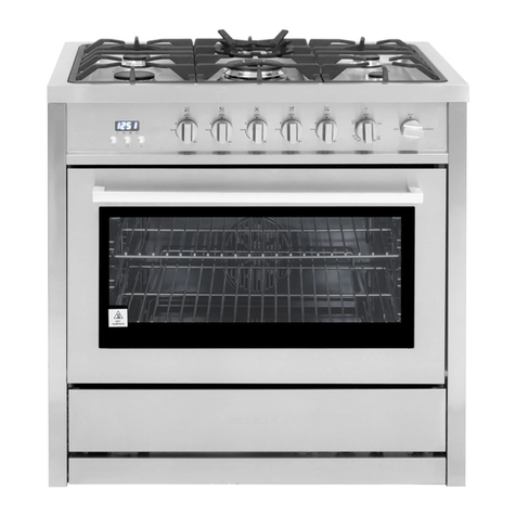
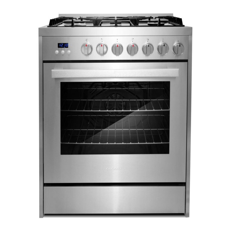
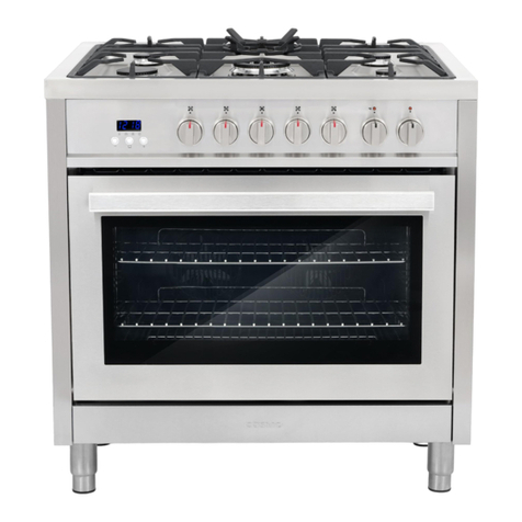
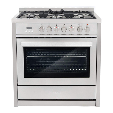
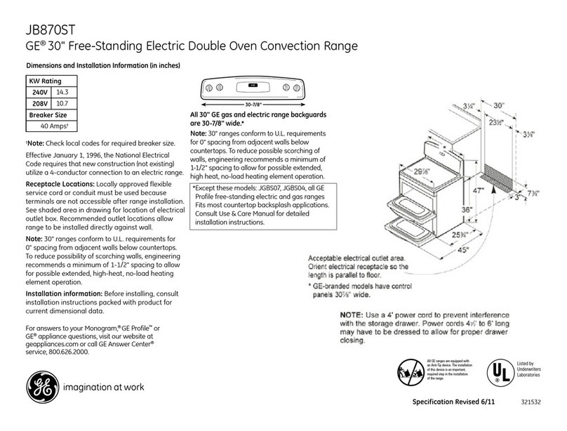
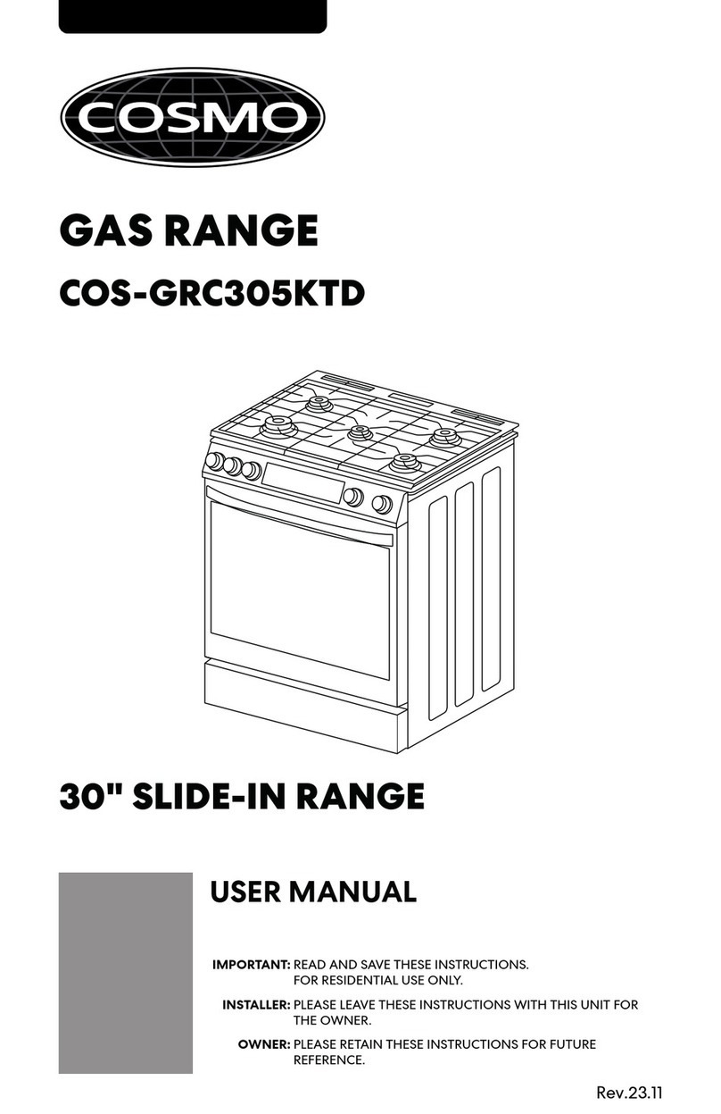
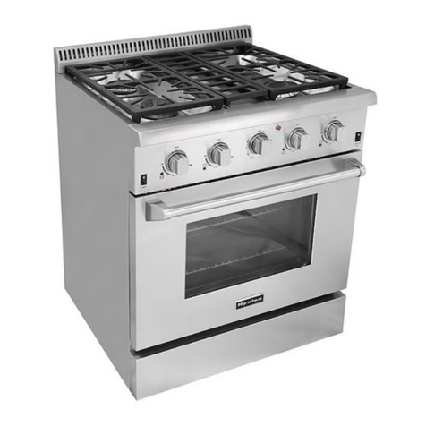
Cosmo COS-ERC305WKTD User manual

Rev.23.11
ELECTRIC RANGE
COS-ERC305WKTD
INSTALLATION INSTRUCTIONS
IMPORTANT:
INSTALLER:
OWNER:
30" SLIDE-IN RANGE
READ AND SAVE THESE INSTRUCTIONS.
FOR RESIDENTIAL USE ONLY.
PLEASE LEAVE THESE INSTRUCTIONS WITH THIS UNIT FOR
THE OWNER.
PLEASE RETAIN THESE INSTRUCTIONS FOR FUTURE
REFERENCE.

2
THANK YOU FOR YOUR PURCHASE
Thank you for your purchase. We know that you have many brands and
products to choose from and we are honored to know that you have decided
to take one of our products into your home and hope that you enjoy it.
COSMO Appliances are designed according to the strictest safety and
performance standard for the North American market. We follow the most
advanced manufacturing philosophy. Each appliance leaves the factory after
thorough quality inspection and testing. Our distributors and our service
partners are ready to answer any questions you may have regarding how to
install, use and care for your products. We hope that this manual will help you
learn to use the product in the safest and most effective manner.
Before using this product, please read through this manual carefully. Keep
this user manual in a safe place for future reference. Please ensure that other
persons using this product are familiar with these instructions as well.
If you have any questions or concerns, please contact the dealer from whom you
purchased the product, or contact our Customer Support at:
1-888-784-3108
Reach us online at:
www.cosmoappliances.com

3
TABLE OF CONTENTS
RANGE SAFETY.................................................................................................... 4
Anti-tip Device........................................................................................................... 5
INSTALLATION REQUIREMENTS ........................................................................ 6
Tools and Parts .......................................................................................................... 6
Location Requirements ............................................................................................ 7
Product Specifications.............................................................................................. 8
Product Dimensions .................................................................................................. 9
Clearances................................................................................................................ 10
Electrical Requirements...........................................................................................12
INSTALLATION INSTRUCTIONS.........................................................................15
Remove Old Appliance ...........................................................................................15
Unpack Range ..........................................................................................................16
Install Anti-tip Device .............................................................................................. 17
Install Rear Trim........................................................................................................19
Electrical Connection..............................................................................................20
Connecting the Power Cord / Conduit ...........................................................20
3-Wire Connection: Power Cord...................................................................... 23
4-Wire Connection: Power Cord......................................................................24
3-Wire Connection: Conduit............................................................................. 25
4-Wire Connection: Conduit.............................................................................26
Complete Installation............................................................................................. 27
Placement and Leveling Range ....................................................................... 27
Verify Anti-tip Bracket Engagement...............................................................30
Removing/Assembling Oven Door.................................................................. 32
Removing/Assembling Drawer ........................................................................34
Checking Operation of the Surface Heating Elements ...............................35
Checking Operation of the Oven ....................................................................36

4
RANGE SAFETY
READ ALL INSTRUCTIONS BEFORE USING THE APPLIANCE
Your safety and the safety of others are very important.
We have provided many important safety messages in this manual and on
your appliance. Always read and obey all safety messages.
This is the safety alert symbol.
This symbol alerts you to potential hazards
that can kill or hurt you and others.
All safety messages will follow the safety alert
symbol and either the word "WARNING" or
"CAUTION." These words mean:
You can be killed or seriously injured if you
don't follow instructions.
A potentially hazardous situation which, if not
avoided, could result in minor or moderate
injury.
All safety messages will tell you what the potential hazard is, tell you how
to reduce the chance of injury, and tell you what can happen if the
instructions are not followed.
WARNING
CAUTION
California Proposition 65 Warning
WARNING:
Cancer and Reproductive Harm - www.P65Warnings.ca.gov.

5
TIP OVER HAZARD
Making sure the anti-tip bracket is installed:
•Slide range forward.
•Look for the anti-tip bracket securely attached
to floor and wall.
•Slide range back so rear range foot is under
anti-tip bracket.
This appliance is intended for normal residential use. It is not approved for
commercial use, outdoor installation, or any other application not
specifically allowed by this manual.
This appliance requires connection to a 3-prong or 4-prong, 240VAC
single-phase (split-phase), 60Hz grounded electrical source. When
installed, appliance must be electrically grounded in accordance with local
codes or, in the absence of local codes, with the National Electrical Code,
NFPA 70 or the Canadian Electric Code, CSA C22.1-02.
Proper installation is the responsibility of the installer. Any adjustment and
service should be performed only by qualified range installers or service
technicians.
Product failure due to improper installation is not covered under warranty.
Anti-Tip
Bracket
Leveling
Leg
WARNING
•A child or adult can tip the range and be killed.
•Install anti-tip bracket to floor or wall per installation instructions.
•Slide range back so rear range foot is engaged in the slot of the anti-tip
bracket.
•Re-engage the anti-tip bracket if range is moved.
•Do not operate the range without anti-tip bracket installed and
engaged.
•Failure to follow these instructions can result in death or serious burns to
children and adults.
WARNING

6
INSTALLATION REQUIREMENTS
TOOLS AND PARTS
Gather the required tools and parts before starting installation. Read and
follow the instructions provided with any tools listed here.
Tools Needed
•Tape measure
•Phillips screwdriver
•Level
•Drill
•1/8" (3.2 mm) drill bit (for wood
floors)
•Masonry drill bit (for
concrete/ceramic floors only)
•Adjustable wrench or pliers
•Marker or pencil
•Safety glasses
•Gloves
Parts Needed
4-Wire cord or 3-Wire cord
(UL approved 40 or 50 AMP)
Strain Relief
Parts Supplied
Rear trim with screws Oven racks Anti-tip bracket with screws

7
LOCATION REQUIREMENTS
IMPORTANT: Observe all governing codes and ordinances. Do not obstruct
flow of combustion and ventilation air.
•It is the installer's responsibility to comply with installation clearances
specified on the model/serial/rating plate. The model/serial/rating plate
is located inside the storage drawer on either the left or right side panel.
•The range should be located for convenient use in the kitchen.
•Recessed installations must provide complete enclosure of the sides and
rear of the range.
•All openings in the wall or floor where range is to be installed must be
sealed.
•Do not seal the range to the side cabinets.
•Cabinet opening dimensions that are shown must be used.
•The anti-tip bracket must be installed.
•Grounded electrical supply is required. See "Electrical Requirements"
section.
•Contact a qualified floor covering installer to check that the floor covering
can withstand at least 167°F (75°C).
•Use an insulated pad or 1/4" (0.64 cm) plywood under range if installing
range over carpeting.
Model/Serial/Rating Plate

8
IMPORTANT: To avoid damage to your cabinets, check with your builder or
cabinet supplier to make sure that the materials used will not discolor,
delaminate, or sustain other damage. This range has been designed in
accordance with the requirements of UL and CSA International and complies
with the maximum allowable wood cabinet temperatures of 194°F (90°C).
Mobile Home - Additional Installation Requirements
•The installation of this range must conform to the Manufactured Home
Construction and Safety Standard, Title 24 CFR, Part 3280 (formerly the
Federal Standard for Mobile Home Construction and Safety, Title 24, HUD
Part 280). When such standard is not applicable, use the Standard for
Manufactured Home Installations, ANSI A225.1/NFPA 501A or with local
codes.
In Canada, the installation of this range must conform with the current
standards CAN/CSA-A240-latest edition, or with local codes.
Mobile Home Installations Require:
•When this range is installed in a mobile home, it must be secured to the
floor during transit. Any method of securing the range is adequate as
long as it conforms to the standards listed above.
•Four-wire power supply cord or cable must be used in a mobile home
installation. The appliance wiring will need to be revised. See "Electrical
Connection" section.
PRODUCT SPECIFICATIONS
Model COS-ERC305WKTD
Description 30" Electric Range
Oven Capacity 6.3 cu. ft.
Electrical Requirements 120/240VAC 60Hz, 120/208VAC 60Hz
Power Ratings Refer to Rating Plate
Exterior Dimensions (WxDxH) 31 ¹⁄₁₆" x 28 ⁷⁄₈" x 36 ³⁄₁₆" (78.9 x 73.3 x 91.9 cm)
Height to Cooking Surface 35 ¹⁄₂" (90.2 cm)
Net Weight 227 lb (103 kg)

9
PRODUCT DIMENSIONS
Your model may appear different from the model depicted. Dimensions given
are maximum dimensions across all models.
COS-ERC305WKTD
NOTE:
•Range can be raised approximately 1" (2.5 cm) by adjusting the
leveling legs.
28 ⁷⁄₈"
(73.3 cm)
Door fully open
36 ³⁄₁₆"
(91.9 cm)
To top of vent
29 ⁷⁄₈"
(75.9 cm)
26 ³⁄₄"
(68.0 cm) 28 ⁷⁄₈"
(73.3 cm)
With handle
35 ¹⁄₂"
(90.2 cm)
Min. height to
flange /cooktop
cooking surface
31 ¹⁄₁₆"
(78.9 cm)
With cooktop flanges

10
CLEARANCES
IMPORTANT: Some cabinet and building materials are not designed to
withstand the heat produced by the oven for baking and self-cleaning. Check
with your builder or cabinet supplier to make sure that the materials used will
not discolor, delaminate or sustain other damage.
GIVEN DIMENSIONS ARE MINIMUM CLEARANCES.
NOTE:
•30" (76.2 cm) minimum clearance between cooking surface and
bottom of the overhead cabinet.
•18" (45.7 cm) minimum clearance from upper cabinet to countertop on
either side of unit.
•Island Installations: Maintain 6" (15.2 cm) minimum clearance from
cutout to back and side edges of countertop.
13 in
(33 cm)
Overhead
Cabinet
Depth
36 in
(91.4 cm)
in18
(45.7 cm)
30 in
(76.2 cm)
30 in
(76.2 cm)
6 in
(15.2 cm)
to right
wall
6 in
(15.2 cm)
to left
wall
24 in
(61 cm)
Lower
Cabinet
Depth

11
Power Supply Location
IMPORTANT: An electrical outlet in the floor, may be either recessed or
surface mounted, but an electrical outlet in the wall must be recessed to make
the connection.
SLIDE-IN
FREESTANDING
25" 23 ¹¹/₁₆"
4"
4"
30"
7"
2"
Electric supply
area
25" 4"
4"
30" 7"
2"
Electric
supply
area

12
ELECTRICAL REQUIREMENTS
ELECTRICAL SHOCK HAZARD
•Do not use an extension cord with this appliance.
•Remove house fuse or open circuit breaker before beginning
installation.
ELECTRICAL GROUNDING INSTRUCTIONS
•This appliance must be properly grounded.
•All new constructions, mobile homes, recreational vehicles and
installations where local codes do not allow grounding through neutral,
require a 4-conductor UL-listed range cord.
U.S.A. ONLY
Be sure that the electrical connection and wire size are adequate and in
conformance with the National Electrical Code, ANSI/NFPA No. 70 - latest
edition and all local codes and ordinances.
A copy of the above code standards can be obtained from:
National Fire Protection Association
1 Batterymarch Park
Quincy, MA 02169
CANADA ONLY
Be sure that the electrical connection and wire size are adequate and in
conformance with the CSA Standard C22.1, Canadian Electrical Code, Part 1 -
latest edition and all local codes and ordinances.
A copy of the above code standards can be obtained from:
Canadian Standards Association
178 Rexdale Blvd.
Toronto, ON M9W 1R3 CANADA
WARNING

13
ELECTRICAL CONNECTION
If codes permit and a separate ground wire is used, it is recommended that a
qualified electrical installer determine that the ground path and wire gauge
are in accordance with local codes.
WARNING: Improper connection of the equipment-grounding conductor can
result in a risk of electric shock. Check with a qualified electrician or service
technician if you are in doubt as to whether the appliance is properly
grounded. Do not modify the power supply cord plug. If it will not fit the
outlet, have a proper outlet installed by a qualified electrician.
To properly install your range, you must determine the type of electrical
connection you will be using and follow the instructions provided for it here.
•This appliance must be supplied with the proper voltage and frequency,
and connected to an individual, properly grounded, 40 amp (minimum)
branch circuit protected by a circuit breaker or time-delay fuse.
•A single-phase (split-phase), 3-wire or 4-wire, AC 120/208 Volt or 120/240
Volt 60 hertz electrical system must be used. It is the personal
responsibility of the range owner to provide the correct electrical service
for this range.
•Effective January 1, 1996, the National Electrical Code requires that new
construction (not existing) utilize a 4-conductor connection to an electric
range. When installing an electric range in new construction, mobile
home, recreational vehicle, or an area where local codes prohibit
grounding through the neutral conductor.
•This range may be connected by means of a conduit or power cord.
•A range cord rated at 40 amps with 120/240 minimum volt range is
required. If a 50 amp range cord is used, it should be marked for use with
13/8" diameter connection openings. Care should be taken to center the
cable and strain relief within the knockout hole to keep the edge from
damaging the cable.
•Use only a 3-conductor or a 4-conductor UL-listed range cord. These
cords may be provided with ring terminals on wire and a strain relief
device.
•Allow 2 to 3 ft (61.0 to 91.4 cm) of slack in the line so that the range can be
moved if servicing is ever necessary.
•A UL Listed conduit connector must be provided at each end of the power
supply cable (at the range and at the junction box).
•The power supply cord and plug should not be modified. If it will not fit
the outlet, have a proper outlet installed by a qualified electrician.

14
•Using an extension cord to connect the power is prohibited. Connect the
power cord and plug directly.
•Wire sizes and connections must conform with the rating of the range.
•If using a GFI breaker, the ground wire must be installed correctly to
prevent breaker from tripping. Refer to latest edition of the NEC, NFPA
No. 70, available from the National Fire Protection Association.
•The wiring diagram is located on the back of the range.
If Connecting to a 3-Wire System:
Local codes may permit the use of a UL listed, 3-wire, 250-volt, 40- or 50-amp
range power supply cord (pigtail).
This cord contains 3 copper conductors with
ring terminals or open-end spade terminals
with upturned ends, terminating in a NEMA
Type 10-50P plug on the supply end.
Connectors on the appliance end must be
provided at the point the power supply cord
enters the appliance. This uses a 3-wire
receptacle of NEMA Type 10-50R.
If Connecting to a 4-Wire System:
This range is manufactured with the ground connected to the neutral by a
link. The ground must be revised so the green ground wire of the 4-wire power
supply cord is connected to the cabinet.
Grounding through the neutral conductor is prohibited for new branch-circuit
installations (1996 NEC); mobile homes; and recreational vehicles, or an area
where local codes prohibit grounding through the neutral conductor.
When a 4-wire receptacle of NEMA Type 14-
50R is used, a matching UL listed, 4-wire, 250-
volt, 40- or 50-amp, range power supply cord
(pigtail) must be used. This cord contains 4
copper conductors with ring terminals or open-
end spade terminals with upturned ends,
terminating in a NEMA Type 14-50P plug on the
supply end.
The fourth (grounding) conductor must be identified by a green or
green/yellow cover and the neutral conductor by a white cover. Cord should
be Type SRD or SRDT with a UL listed strain relief and be at least 4 ft (1.22 m)
long.
3-wire receptacle (10-50R)
4-wire receptacle (14-50R)

15
INSTALLATION INSTRUCTIONS
IMPORTANT: This appliance shall be installed only by authorized persons and
in accordance with the manufacturer's installation instructions, municipal
building codes, and electrical wiring regulations.
REMOVE OLD APPLIANCE
ELECTRICAL SHOCK HAZARD
•Remove house fuse or open circuit breaker to disconnect power before
servicing. Failure to do so can result in death, fire, or electrical shock.
EXCESSIVE WEIGHT HAZARD
•Use two or more people to move and install range. Failure to do so can
result in back or other injury.
LACERATION, FOREIGN OBJECT, CRUSH HAZARD
•When installing, moving, or servicing any appliance, wear proper
protective equipment, including cut resistant gloves, steel-toed shoes,
and safety glasses.
1. Shut off the electrical supply to the old range at the breaker box or fuse
box. Leave it off until the installation has been completed.
WARNING
WARNING
CAUTION

16
For old gas ranges, shut off the gas supply valve to the range before
disconnecting the range and leave it off.
2. Move appliance to access the electrical connection and gas connection if
applicable.
3. Disconnect electrical connection and gas connection if applicable, and
move appliance out of and away from installation space.
UNPACK RANGE
EXCESSIVE WEIGHT HAZARD
•Use two or more people to move and install range. Failure to do so can
result in back or other injury.
1. Remove all tape and packaging materials. Check for film on stainless
steel parts, padding/spacers on and around door and face of oven,
cardboard and plastic on and around racks, inside storage drawer, etc.
Failure to remove packaging materials could result in damage to the
appliance.
NOTE:
•Do not remove any warning-type labels, the model and serial
number label, or the Tech Sheet that is located on the back of the
range.
•Do not use sharp instruments, rubbing alcohol, flammable fluids,
or abrasive cleaners to remove tape or glue. These products can
damage the surface of your range.
•Do not push or pull the range by grabbing the open oven door or
cooktop only. Doing so can result in serious damage to the range.
•Do not lift the range using the cooktop or oven door handle. Doing
so can cause damage and improper operation of the range.
•Do not dispose of anything until the installation is complete.
WARNING

17
NOTE:
•To reduce the weight of the range while being moved, adjusted,
and installed, detach the oven door and remove the bottom
drawer from the range. See "Removing/Assembling Oven Door"
and "Removing/Assembling Drawer" sections.
INSTALL ANTI-TIP DEVICE
IMPORTANT:
•An anti-tip bracket is provided with the range. The anti-tip bracket uses a
rear range foot to secure the range to the floor or wall.
•Attach the anti-tip bracket to the floor or wall so that the rear range foot
will be centered within the bracket when the range is pushed into its final
position.
TIP OVER HAZARD
•A child or adult can tip the range and be killed.
•Install anti-tip bracket to floor or wall per installation instructions.
•Slide range back so rear range foot is engaged in the slot of the anti-tip
bracket.
•Re-engage the anti-tip bracket if range is moved.
•Do not operate the range without anti-tip bracket installed and
engaged.
•Failure to follow these instructions can result in death or serious burns to
children and adults.
WARNING

18
1. Using the template provided with anti-tip kit, locate the preferred
location for installation of the anti-tip bracket and mark the location of
the screw holes. Bracket may be installed at either the back-left or back-
right corner of the installation space.
NOTE:
•Only one anti-tip bracket needs installed.
2. Follow the instructions specific to your construction.
Wood Construction
•Drill a 1/8" pilot hole where screws are to be located. If bracket is to
be mounted to the wall, drill pilot hole at an approximate 20°
downward angle. Screw must enter wood.
Masonry Construction
•Due to the variety of masonry materials that may be present at
installation site, hardware is not provided for attaching the anti-tip
bracket to masonry. If bracket is to be mounted to masonry or
ceramic floors, attach anti-tip bracket using two 5/16" OD sleeve
anchors (with 1/4" bolt - either hex bolt head or hex nut head) rated
for minimum 300lb tension for the masonry material present at
installation site. Screw must enter masonry.
3. Secure anti-tip bracket to floor or wall with the screws provided.
More than 1-1/4"
Anti-tip bracket
Leveling leg
Mounting screw (floor)
Wall
Installation with
rear left leg
Installation with
rear right leg
or

19
INSTALL REAR TRIM (OPTIONAL)
If there is no counter surface around the back edge of the installation space,
or if the countertop cutout is greater than 25" deep, this may prevent the
range from being installed flush to the back wall. A rear trim can be installed
to cover a gap up to 1 inch in width.
Counter continues around behind
installation space - no rear trim
required.
No countertop behind at back of
installation space - rear trim
recommended.
1. Align rear trim mounting holes.
2. Secure rear trim with the screws provided.

20
ELECTRICAL CONNECTION
ELECTRICAL SHOCK HAZARD
•Remove house fuse or open circuit breaker to disconnect power before
servicing.
•This appliance must be properly grounded.
•Do not use an adapter or an extension cord.
•Failure to do so can result in death, fire, or electrical shock.
CONNECTING THE POWER CORD / CONDUIT
1. Access the range electrical terminal block by removing the screw
attaching the terminal block access cover on the back of the range.
WARNING
Other manuals for COS-ERC305WKTD
1
Table of contents
Other Cosmo Range manuals

Cosmo
Cosmo cos-965ag User manual

Cosmo
Cosmo GRP Series User manual

Cosmo
Cosmo COS-305AGC User manual

Cosmo
Cosmo F965 User manual

Cosmo
Cosmo COS-305AERC User manual

Cosmo
Cosmo COS-305AEC User manual

Cosmo
Cosmo F965NF User manual

Cosmo
Cosmo COS-244AGC User manual

Cosmo
Cosmo COS-965AGC User manual

Cosmo
Cosmo COS-244AGC User manual

Cosmo
Cosmo COS-F965 User manual

Cosmo
Cosmo COS-GRP304 User manual

Cosmo
Cosmo COS-DFR366 Troubleshooting guide

Cosmo
Cosmo COS-965AGC User manual

Cosmo
Cosmo COS-EPGR User manual

Cosmo
Cosmo COS-965AGC User manual

Cosmo
Cosmo COS-ERC305WKTD User manual

Cosmo
Cosmo COS-305AGC User manual

Cosmo
Cosmo GRP Series User manual
Cosmo
Cosmo GRP Series User manual