Howmet Aerospace HuckForce HK32-002 User manual

In truction Manual
HK32-002
HuckForce
Hydraulic Powerig
(original in truction )
Manufacturer:
Howmet Fastening Systems Ltd; Telford, United Kingdom
Form o. HK32-002 E
Rev. 06.01.23
Previous revision: 10.07.19
Serial Number: __________________

2
HK32-002 Se ies Howmet
EG-Konformitätserklärung
EC-Declaration of Conformity
Im Sinne der EG-Richtlinie 2006/42/EG über Maschinen (Anhang IIA)
According to EC Machinery directive 2006/42/EC (Annex IIA)
Name und Anschrift des Herstellers / Name and address of the manufacturer:
Seyer Antriebs- und Verbindungstechnik GmbH
Am Bahnhof 7
D-37520 Osterode am Harz
Diese Erklärung bezieht sich auf die Maschine in dem Zustand, in dem sie in Verkehr gebracht wurde. Vom
Endnutzer nachträglich angebrachte Teile und/oder nachträglich vorgenommene Eingriffe bleiben
unberücksichtigt. Die Erklärung verliert ihre Gültigkeit, wenn das Produkt ohne Zustimmung umgebaut oder
verändert wird.
This declaration relates exclusively to the machinery in the state in which it was placed on the market, and
excludes Components which are added and/or operations carried out subsequently by the final user. This
declaration is invalid, if the product is modified without agreement.
Hiermit erklären wir, dass die nachstehend beschriebene Maschine
Herewith we declare, that the machinery described below
Produktbezeichnung / Product Denomination: Powerig
Serien- / Typenbezeichnung / Model / Type: HK32-002, Serien-Nr. / Serial-No. 5000 - 9999
Baujahr ab / Year of Manufacture, since: 2015
allen einschlägigen Anforderungen der Maschinenrichtlinie 2006/42/EG sowie der Richtlinie 2014/30/EU
über elektromagnetische Verträglichkeit entspricht.
Die Schutzziele der Richtlinie 2014/35/EU über elektrische Betriebsmittel werden eingehalten.
is complying with all essential requirements of the Machinery Directive 2006/42/EC and Directive
2014/30/EU relating to electromagnetic compatibility.
The safety objectives of the Directive 2014/35/EU relating to electrical equipment are observed.
Weitere angewandte harmonisierte Normen / Further applied harmonized Standards:
EN ISO 12100 Sicherheit von Maschinen - Allgemeine Gestaltungsleitsätze - Risikobeurteilung und
Risikominderung / Safety of machinery - General principles for design - Risk assessment and risk reduction
EN 60204-1 Sicherheit von Maschinen - Elektrische Ausrüstung von Maschinen - Teil 1: Allgemeine
Anforderungen / Safety of machinery - Electrical equipment of machines - Part 1: General requirements
EN ISO 4413 Fluidtechnik - Allgemeine Regeln und sicherheitstechnische Anforderungen an
Hydraulikanlagen und deren Bauteile / Hydraulic fluid power - General rules and safety requirements for
systems and their components
Bevollmächtigter für die Zusammenstellung der relevanten technischen Unterlagen /
individual authorised to complete the relevant technical documentation:
Duro Brmbota - Am Bahnhof 7 - D-37520 Osterode am Harz
Osterode, d. 15.09.2022
Axel Lüddeke, Geschäftsführer

3
HK32-002 Se ies Howmet
Contents
Safety Guidelines when using Huck Installation Equipment
to install Huck Fasteners 1 - 3
General Description 4
Specification 5 - 7
Utilisation 9
Servicing Powerig 10
HK32-002 Main Components & Controls 11
HK32-002 Hydraulic Schematic 12
HK32-002 Electrical Schematic 13 - 14
Function 15
Preparation for First Time Use 16 - 19
Preparation for Regular Use 20
Parts Lists 24 - 25
Preventive Maintenance & Maintenance 26 - 27
Service Notes 28 - 29
Limited Warranties 30
Control Amendment 1.0 31-34

HK32-002 Se ies Howmet
1
Safety Guidelines when using Huck
Installation Equipment to install Huck
Fasteners.
Before using or maintaining the
equipment:
WARNING THIS POWERIG HAS A HIGH
PRESSURE HYDRAULIC SYSTE . TO
HELP AVOID PERSONAL INJURY, THE
FOLLOWING UST BE APPLIED:
1) Never begin work on a hydraulic or
pneumatic system without carrying out a
risk assessment.
2) Never begin work on a hydraulic
system until fully trained.
3) Carefully review the manuals on
equipment before beginning work. Ask
questions about anything you do not fully
understand.
4) Review the Material Safety Data
Sheets (MSDSs) for all substances used.
5) Maintain a clean work area free of
slipping hazards and debris.
6) Use all required safety equipment.
7) Eye protection must be worn when
using or maintaining this Powerig.
8) Approved work overalls/clothing
and safety footwear must be worn when
using or maintaining this Powerig.
9) Never begin work on a hydraulic
system until you are certain that any
residual system pressures are
depleted/relieved. ( Some systems use
accumulators that store pressure.
Identify the system before working on
it).
HUCK FASTENING SYSTE S
10) Do not operate the Powerig
without covers in their proper position.
11) Use extreme caution when
disconnecting hydraulic components. Hot
fluid can result in severe burns.
12) Use test equipment designed for
higher pressures than the system being
repaired. Use of gauges, pipe work,
hoses, connectors, etc., designed for
lower pressures can result in bursting or
equipment damage. Start with high
pressure gauges and work down. (Note: A
good rule is to use equipment rated at
twice what is expected. Example: For a
2500 psi/172 bar system, use 5000
psi/345 bar gauge).
13) DO NOT USE HANDS OR
FINGERS to find leaks. Fluid under high
pressure can be injected into skin
(hypodermic puncture), causing extreme
injury and serious infection.
14) Clean up spills immediately.
Hydraulic fluid is an oily substance which
can cause slipping, falling and resulting
personal injuries.
15) Only Huck Installation Equipment
should be used to install Huck fasteners.
16) Only persons that have received
training approved by Huck International
Ltd should use Huck Installation
Equipment.
17) The Manuals and/or Data sheets and
warning stickers/labels supplied with the
Installation equipment should be studied
before connecting the equipment to any
primary power supply, in particular the
following sections:
Continued on next page...

2
HK32-002 Se ies Howmet
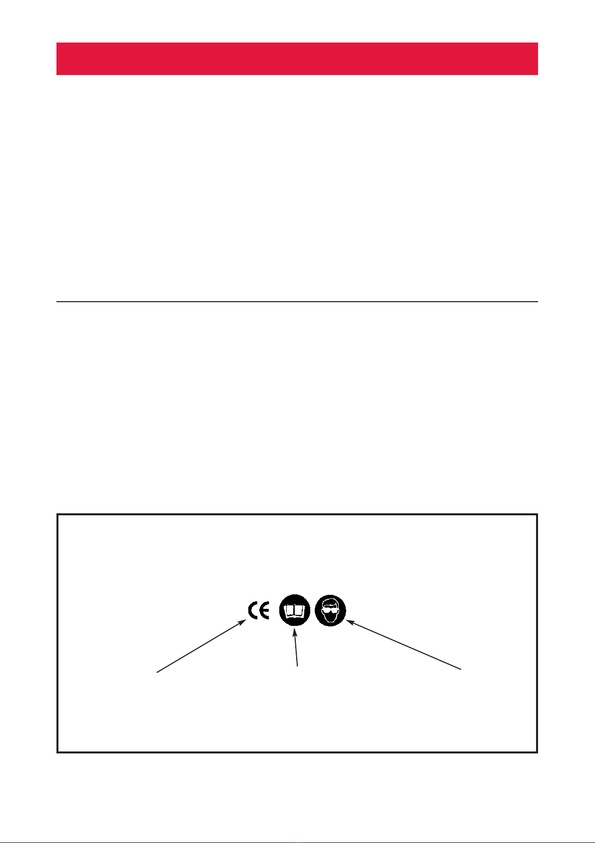
• Warnings and Cautions.
• Specifications
• Electrical and/or Air supply.
• Principals of Operation.
• Preparation for use.
• Regular use.
• Regular maintenance.
18) With hydraulic tooling, ensure that it is
suitable for use with the Huck Powerig or
Huck approved hand pump being used.
19) Check that the Powerig or approved
hand pump "Pull" and "Return" pressures
have been adjusted to suit the tool
being used. Reference must be made to
the instruction manual supplied with the
equipment.
20) Check that the Nose Assembly is of
the correct type suitable for installing the
fastener being used.
21) Visually check all pneumatic and/or
hydraulic hoses, electrical cables,
Powerigs, hand pumps and hand tools, for
any visible signs of damage and leakage.
ALL HYDRAULIC HOSES SHOULD BE
RENEWED EVERY FIVE YEARS.
22) Do not connect any equipment to
primary power supplies or attempt to use
any equipment, that shows signs of
damage or leakage.
23) Ensure that all air and/or hydraulic
hose and/or electrical plugs/connectors
are correctly connected before switching
on supply to equipment.
When operating the equipment:
24) When using fasteners in some types
of structure, the fracturing of the pintail
during installation may generate noise
levels above the first action level of the
Noise at Work Regulations and therefore
hearing protection must be worn.
25) It is recommended that eye protection,
(e.g.. safety glasses), should be worn by
the operator.
26) Never look directly at the front or rear
of the installation tool.
27) Never hold the Installation Tool around
the Nose Assembly.
28) Keep hands/fingers clear of any
moving parts and also apertures in Nose
Assemblies.
29) Warning
Fasteners should only ever be installed in
the actual workpiece to prevent possible
high velocity ejection from the Nose
Assembly due to tensile forces induced
during pintail fracture.
30) When using two piece fasteners, (i.e..
Pin and Collar type), the
conical/chamfered end of the collar UST
always be towards the Nose assembly,
NOT against the work piece.
31) Keep fingers clear from the underside
of the head, collars and blind side of
fasteners and from within the joint being
fastened, during the installation cycle.
32) Do not look directly at the head or
blind side of fasteners during the
installation cycle.
33) During the installation cycle, the tool
will pull and straighten itself to the axis of
the fastener, beware of hands being
trapped against any nearby structure.
KEEP HANDS CLEAR
34) In the event of any difficulty whilst
installing a fastener, releasing the tool
trigger at any time during the installation
Continued on next page...

HK32-002 Se ies Howmet
3
Note
The following symbols are attached to the equipment:
The equipment ,meet the
requirement of CE
Certification.
Read the In truction Manual
before u ing or maintaining thi
equipment.
Wear eye protection when
u ing thi equipment.
36) Do not continue to use any
equipment which develops a fault whilst
being used.
37) Avoid kinking of hoses or dragging of
hoses and electrical cables over sharp
objects.
38) The Powerig should only be used with
the Cover secured in place.
cycle will immediately put the tool into
reverse.
35) Beware of fastener pintails which are
ejected, (sometimes forcibly), from the
tool at the completion, or at pintail
fracture, during the installation cycle.
Tools designed to have Pintail
Deflectors and or catchers must never
be used without them.

HK32-002 Se ies Howmet
4
General Description
TThe electrically operated HK32-002 Powerig is
designed to operate Huck hydraulic Installation
Tools, (See Utilisation).
The maximum hydraulic Pull Pressure and Return
Pressure is 580 bar (8410 psi).
The Powerig hydraulic Directional Valves plus
control circuits, are powered from a 24 Volt DC
remote circuit activated by the Tool Trigger via the
PLC.
Huck Installation Tools are connected to the
Powerig by means of Pull & Return Hydraulic
Hoses and an Electrical Control Cord fitted with
connectors.
The functions of the Motor/Pump and hydraulic
valves are controlled by the PLC during fastener
installation. The Tool Trigger is depressed to start
the installation sequence. The Powerig
Motor/Pump will start (if it is not already running in
the idle mode), and the Tool Piston/ ose Assembly
will move to start the Fastener Installation cycle.
Depending on the type of Tool used and the
Fastener being installed, the Tool Piston/ ose
Assembly will automatically return to their original
start positions when the hydraulic Swage Pressure
is detected by the Digital Pressure Switch; or the
operator releases the Tool Trigger. However, the
Tool Trigger must be released to re-set the
programme to install the next fastener.
The Powerig Motor/Pump will continue to run in an
idle condition but will stop after 2 minutes
(adjustable) if the Tool Trigger is not activated
within that time.
In the event of the hydraulic oil temperature
exceeding 80°C, a Temperature Switch will be
activated and stop the Motor/Pump from operating
to prevent component damage.
In order to protect the hydraulic fluid from
contamination particles, a 10 & 60 micron filters are
incorporated in the hydraulic system.
The PLC Module (1A1) has two Counters (not re-
settable), which record the total number of Tool
cycles and the Powerig operating time.
An Oil Level Switch will detect if the hydraulic oil
level in the reservoir is too low and stop the
Motor/Pump from operating to prevent component
damage.
If higher than normal electrical load (Amperage)
detected, then an Amps Overload Trip will activate
and the Powerig automatically stops.

HK32-002 Se ies Howmet
5
Specification
Powerig Type HK32-002
Flow l/min. (See Note1) 3.2 (50Hz)/3.85 (60Hz)
Hydraulic System Pressure Max.bar(psi) 600 (8700)
Pull Pressure relief valve sealed (See Note 2) YES 580 bar (8410 psi)
Return Pressure Max.bar(psi) 580 (8410)
Electrical Power Supply Requirement 3 x 400/440 VAC ± 10% 50Hz
(See Note 3) 3 x 400/440 ± 5% 60Hz
Motor (1420 rpm) kW 2.2
Amps Nominal 5.2 to 9.0 (50Hz)
(depending on voltage supply) 4.5 to 8.3 (60Hz)
Hydraulic Pump Piston - 6 Cylinder
Control Circuit 24 Volts DC
PLC Type: Siemens LOGO
Noise Level Max. 77.6 dBA
Working Area ambient Temperature Maximum 40° C (104° F)
Reservoir Capacity Max. 6.9 litre
Idler Valve Version: YES
Idling Time: 2 minutes (adjustable)
Oil Filter - Reservoir (in Idler mode): YES 10 microns
Oil Filter - Inline (Pull / Return): YES, 100 microns
Indicator for Oil Temperature Switch YES (PLC Screen)
Digital Counter for each Fastener installation YES (PLC Screen - not resettable)
(See Note 4)
Digital Time Recorder (operating time) YES (PLC Screen - not resettable)
(See Note 4)
Warranty Maximum (whichever occurs first) 12 Months or 1 million cycles
Length 72 cm
Width 50 cm
Height 80 cm
Weight (incl.oil) 86 kg
Hydraulic Oil: HLP - D 46 (BP or equivalent)
Continued on next page...

HK32-002 Se ies Howmet
6
Specification continued
CAUTION
The hydraulic output pressure valves
(pull & return) on this Powerig have
been set and sealed by the
manufacturer and should only be
changed in accordance with the
instructions shown in this manual.
Any new pressures set must always be
checked and tested.
CAUTION
The Powerig should not be used as a
step. No person should climb on the
Powerig.
CAUTION
The Powerig should not be used in an
explosive and/or highly flammable
atmosphere.
Notes:
1) When operated at 60Hz power supply,
oil flow increases by a factor of 1.2.
2) If the Powerig is delivered without an
Installation Tool Pull Pressure is factory
preset at 393 bar, (5700 psi). If the
Powerig is delivered without an
Installation Tool, Return Pressure is
factory preset at 165 bar, (2400 psi).
3) The operating voltage is shown on the
Powerig nameplate. When ordering new
units, state exact 3 phase power supply.
To operate on other voltages, please
contact Howmet Fastening Systems &
Rings, Systems Engineering team.
4) The electrical connection on both
Counters has been sealed. If there is
evidence that this sealing is damaged
and/or the Counters show zero, then the
Warranty on this unit is invalidated.

HK32-002 Se ies Howmet
7
FIG. 1
HK32-002 Dimensions
500
800
720
ALL DIMENSIONS
IN mm

8
HK32-002 Se ies Howmet
Noise
The sound measurement is in accordance
with EU 2000/14/EC and DIN EN ISO
For more information with respect to the
management of waste equipment for recycling
please contact our Customer Services desk at
Howmet Fastening Systems & Rings, Telford
Shropshire TF3 3BQ.
The Producer Identification umber for Howmet
Fastening Systems & Rings, Telford is:
WEE/AF0044SY
Intended Use
The HK32-002 series Powerigs are
designed to be used with various Huck
Installation Tools to install various Huck
Fasteners, in a normal, factory working
environment. The unit should be placed
on a level surface and kept in a clean dry
area.
Disposal
Metallic and non-metallic
parts/components/materials, (including
any fluids), should be disposed of by
processing through authorised methods
and in accordance with current legislation
including European Directive 2002/96/EC
on Waste Electrical and Electronic
Equipment (WEEE).
This symbol indicates that this product
must be disposed of according to the
WEEE Directive and our national law.
Products of this nature should be
forwarded to a designated collection point
e.g. on an authorised one-for-one basis
when you buy a similar new product or to
an authorised collection site for recycling
waste electrical and electronic equipment
(EEE). Improper handling of this type of
waste could have a possible negative
impact on the environment and human
health due to potentially hazardous
substances that are generally associated
with EEE. At the same time, your co-
operation in the correct disposal of these
products will contribute to the effective
usage of natural resources.
The Waste Electrical &
Electronic Equipment
Regulations 2006

HK32-002 Se ies Howmet
9
Pressures - definitions
Notes:
1) The above pressure values are only intended a a guide. The actual values required may vary
according to the system set up, (e.g. Hose Set length, Collar surface finish).
2) Where TBA (to be advised) is shown under Swage Pressure, please contact Howmet Fastening Systems
& Rings - Systems Engineering for advise.
Huck Tool Pull Pressure Return Pressure
Series/ odel ax. bar/psi ax. bar/psi
2400, 2480, 2582, 2583 579/8400 221/3200
2502, 2503 579/8400 165/2400
2580 Series 393/5700 221/3200
2600 Series 393/5700 193/2800
2581, 2620,2624, 2628, 2630 Series 510/7400 221/3200
506, 507, 585, 586, 5901, 393/5700 165/2400
516, 520, 524, 528, 532, 536
6042, 7042, 8042 510/7400 221/3200
Utilisation
Swage Swage
ax Pressure Pressure ax.
Pull Installation Collar Return
Bobtail Tool Fastener Fastener Pressure Nose Assy. Cutter Pressure
Series Diameter Grade bar/psi bar/psi bar/psi bar/psi
2480 3/16” (4.8 mm) 8.8 136/1972 125/1813 TBA 125/1813
2503 5/16” (7.9 mm) 8.8 242/3509 TBA TBA 175/2538
2620 Seri. 1/2” (12.7 mm) 10.9 510/7400 190/2755 150/2175 221/3200
BTT25 12 mm 10.9 389/5640 289/4200 235/3408 289/4200
BTT25 14 mm 10.9 389/5640 340/4930 290/4205 289/4200
BTT35 16 mm 10.9 380/5510 357/5177 270/3915 350/5075
BTT57 20 mm 10.9 455/6598 300/4350 250/3625 448/6500
BTT20SF 16 mm 10.9 525/7612 500/7250 250/3625 345/5002
Pull Pressure:
This is the maximum hydraulic pressure
which can be applied to the Tool Piston
during the “Pull” stroke (pulling on the
Fastener Pin), enabling the complete
Fastener installation. It is set and
adjusted with the Pressure Limiting Valves
(30).
Swage Pressure:
Sometimes called Cut-Off Pressure, this is
the hydraulic pressure which is applied to
the Tool Piston during the “Pull” stroke
(pulling on the Fastener Pin). This
pressure is set using the Digital Pressure
Switch (19). It is adjusted to ensure
complete swaging of the Collar and/or
pintail fracture when the value of the set
Swage Pressure is reached, at which
point, the Tool Piston will automatically
return to it’s starting position. This
pressure will normally be set lower
than the Pull Pressure.
Return Pressure:
This is the hydraulic pressure applied to
the Tool Piston during the Tool Piston
return stroke, enabling the Tool/Nose
Assembly to eject from the installed
Fastener.
This pressure is set and adjusted with the
Digital Pressure Switch (19A) and to
function correctly, it must be set at a
lower value than the Mechanical Pressure
Relief Valve 30A.

10
HK32-002 Se ies Howmet
Servicing Powerig
Only a qualified mechanic or electrician
should service any hydraulic or pneumatic
components, install electrical supply
cable, or service the electrical control box
or electrical components.
Howmet Fastening Systems & Rings
Account Managers and Systems
Engineers are located in your area to offer
assistance you require in solving your
installation problems.
If necessary, contact Howmet Fastening
Systems & Rings, Systems Engineering
Department.
Electrical Earth Bond Continuity &
Electrical Insulation Test (Flash Test)
Before carrying out the above test on this
Powerig, the DPU 6 and the , PLC Module
10 and must be isolated from the
electrical system. Failure to do this will
cause permanent damage to those units.

HK32-002 Se ies Howmet
11
Oil Fill Connector (hidden) 22
Hydraulic Directional
Valve (HDV)
(Return Pressure)
42
24VDC Electrical
Base Connectors
(Bobtail Tools)
30
Mechanical Pressure
Limiting Valve
(Pull Pressure)
19A
Digital Pressure
Switch
(Return Pressure)
43
Electrical Base
Connector – Huck
Tools
20
Hydraulic QD Coupling
(Pull Pressure)
Electrical
Supply Cable
37
Wheel Kit
12
Emergency
Stop Button
15
Main Switch
FIG. 2 ain Components & Controls - HK32-002
21
Hydraulic QD Coupling
(Return Pressure)
16
Oil Filter Condition
Gauge
14
Canister Oil Filter -
10 micron
(Oil Reservoir)
26
Hydraulic Directional
Valve (HDV)
(Pull Pressure)
24
Idler Valve
39
Eject Button
18
Motor/Pump Assembly
30A
Mechanical Pressure
Limiting Valve
(Return Pressure)
23
Main Pressure
Limiting Valve
19
Digital Pressure
Switch
(Pull Pressure)

HK32-002 Se ies Howmet
12
R
INSTALLATION TOOL
Ref. No. Part Number Item
26 (1V1) HMP-0012 HYDRAULIC DIRECTIO AL VALVE (PULL PRESSURE)
22 (1V2) HMP-0013 HYDRAULIC DIRECTIO AL VALVE (RETUR PRESSURE)
24 (1V3) HMP-0014 HYDRAULIC IDLER VALVE
19 (1B2) HMP-0010 DIGITAL PRESSURE SWITCH (PULL PRESSURE)
19A (1B3) HMP-0010 DIGITAL PRESSURE SWITCH (RETUR PRESSURE)
23 HKH-9095 MAI PRESSURE RELIEF VALVE
30 HMP-0016 MECHA ICAL PRESSURE LIMITI G VALVE (PULL PRESSURE)
30A HMP-0016 MECHA ICAL PRESSURE LIMITI G VALVE (RETUR PRESSURE)
LEGEND
FIG. 3
HK32-002 Hydraulic Schematic
19A
(1B2)
22
(1V2)
26
(1V1)
24
(1V3)
1B1
1B4
P
INSTALLATION TOOL
23 30 30A
19
(1B3)

HK32-002 Se ies Howmet
13
FIG. 4
HK32-002 Electrical Schematic - page 1

HK32-002 Se ies Howmet
14
FIG. 4A
HK32-002 Electrical Schematic - page 2

HK32-002 Se ies Howmet
15
Function (Refer to FIGS. 3 & 4)
After connection of the Powerig to a 3
phase electrical supply, the Main Switch
15/1Q1 should be switched to the on
position and the Emergency Stop 12 in
the reset position, (Button pulled out). In
this condition, contacts of the Emergency
Stop 13/1S4, Overload Trip 2/1F4, Oil
Temperature Switch B1, Oil Level Switch
B4 are closed.
The Transformer 5/1 4 develops a
secondary 24 Volt DC circuit across the
Tool Trigger 1S1.
When Tool Trigger 1S2E or 1S3E is
depressed, (closing contacts), a PLC
output energises the Motor Contactor
1/K7, (unless the Motor/Pump is already
running),closing contacts to start the
Motor/Pump 18/1 3. HDV’s (Hydraulic
Directional Valves), 26/1V1, 22/1V2 &
Idler Valve 24/V3 are also energised by
outputs from the PLC.
Pressurised Hydraulic Oil is directed
through outlet P (Pull Pressure) to the
front of the Tool Piston. The Tool
Piston/Nose Assembly Collet, move
rearwards to start the Fastener
installation. Excessive Oil is pushed
through outlet R into the reservoir via
HDV 22/1V2. The Pull Pressure is
controlled by the setting of the Digital
Pressure Switch 19/1B2.
When the Tool Trigger is released, signals
from the PLC de-energise the HDV’s
26/1V1 & 22/1V2. Pressurised Oil is then
directed to outlet R (Return Pressure) to
the rear of the Tool Piston The Tool
Piston/Nose Assembly Collet moves
forward and excessive Oil is pushed
through outlet P into the reservoir via HDV
26/1V1.
When the Tool Piston reaches the fully
forward position, the Oil pressure (Return
Pressure) rises. When the Return
Pressure reaches the set value of the
Digital Pressure Switch 19A/1B3, a signal
via the PLC, de-energises the HDV’s and
Idler Valve 24/V3 and the Motor/Pump
continues to run in the idle condition,
circulating the Oil through the 10 micron
Cannister Filter 14. After 2 minutes,
unless the Tool Trigger is activated, the
PLC will give a signal to de-activate the
Motor Contactor and stop the
Motor/Pump.
Notes:
A)
The Temperature Switch B1 protects the
system from overheating. When it is
activated, (at approximately 80°C Oil
temperature), the Motor/Pump will not
operate. This to prevent component
damage.
B)
If the Oil level falls too low, the Oil Level
Switch B4 is activated and the
Motor/Pump may not operate. This to
prevent component damage.
C)
The Pressure Limiting Valve 23 is pre-set
for the maximum system pressure and
protects the hydraulic circuit from
overloading.
D)
The Amps Overload Trip 1/1F4 protects
the motor from overheating due to
incorrect voltage supply or overload. The
Contacts can be reset by manually with
the Button on the Amps Overload Trip.
I PORTANT
The electrical connection on both
Counters has been sealed. If there is
evidence that this sealing is damaged
and/or the Counters show zero, then the
Warranty on this unit is invalidated.

HK32-002 Se ies Howmet
16
Preparation for First Time Use - Hydraulic System (Refer to FIG. 5)
Continued on next page...
1. Check that Oil Drain Connector/Plug 29
& 29A are in place and tightened.
2. Using the Oil Level Sight Glass the oil
level should not be more than 2,5 cm
below the full line otherwise the Powerig
may not operate. Oil must be added to re-
set the Oil Level Switch. Further Oil must
be added to bring the level back the full
line.
3. If it is necessary to add Oil, remove the
Powerig Breather from the connector.
(Refer to page 28).
CAUTION
For filling the reservoir, only use Oil
that has passed through a 10 micron
Filter. Clean Funnels and Containers
etc. mu t be used.
Failure to do this will result in damage
to the Flow eter.
4. Clean any oil spillage with absorbent
wipes and replace the Breather and
tighten.
5. Connect electrical power supply cable
to correct 3 phase electrical supply, as
specified on the Powerig name plate.
6. Turn Main Switch 15 to the on position
and pull out Emergency Stop button 12 to
the reset position.
Checking & Adjusting the Pull
Pressure - PLV ( echanical
Pressure Limiting Valve) 30
(refer to page 9 for correct setting)
Note:
Before proceeding, adjust the DPS (Digital
Pressure Switch) 19 to 600 bar
(8700 psi). Refer to page 19.
WARNING
TO AVOID THE RISK OF PERSONAL
INJURY, DO NOT CONNECT ANY
HYDRAULIC HOSES TO THE POWERIG
AT THIS TI E.
Checking Pull Pressure
(refer to Utilisation page 9, for correct
setting)
7. Connect the electrical plug of a remote
trigger or Installation Tool to the Powerig
Electrical Connector 43.
8. Operate the remote/Tool Trigger
momentarily and note the Pull Pressure
reading on the DPS 19.
CAUTION
Complete this test as quickly as
possible to prevent overload of
hydraulic components. Only use
reliable accurate gauges.
Note:
The Powerig Motor/Pump will continue to
run in an idle condition but will stop after 2
minutes if the Tool Trigger is not activated
within that time.
9. Refer to FIG. 5 (Item 30) and adjust the
Pull Pressure to suit the Installation Tool
being used. Refer to the Installation Tool
Instruction Manual for correct Pull
Pressure setting. Only make small
adjustments (1/4 turn) at one time.
Do not remove any pre-installed washers
Oil Level
Sight Glass
Breather Cap
Filler Cap

HK32-002 Se ies Howmet
17
Lock ut
Remove Cover to acce Adju tment
Screw
Adjustment Screw:
Clockwi e to increase Pull Pressure
FIG. 5
echanical Pressure Limiting Valves 30 & 30A
Pull & Return Pressure
and locknut from the adjusting screw.
Note:
It will only be possible to adjust the
Mechanical Pressure Limiting Valves at a
lower pressure than the Main Pressure
Limiting Valve 23.
10. Connect both hoses of the Tool to the
Powerig. Activate the Tool Trigger to cycle
the Tool, holding the trigger for approx. 20
seconds when the Tool Piston is in the
fully back position. Release the Trigger
and allow the Tool Piston to return to the
fully forward position. Repeat three times.
This will ensure that any air in the
hydraulic system is removed.
11. Check the Pull Pressure again as
described in steps 7 -10 above.
12. Once the Pull Pressure has been set,
use the Lock Nut to ensure setting is
retained. Check the pressure one more
time to ensure it had not changed whilst
tightening the Lock Nut.
30
Mechanical Pressure
Limiting Valve
(Pull Pressure)
30A
Mechanical Pressure
Limiting Valve
(Return Pressure)
Continued on next page...
Cover
Table of contents
Popular Industrial Equipment manuals by other brands

Roemheld
Roemheld SPEEDY basic S operating instructions

Doosan
Doosan LPS LINE manual

Siemens
Siemens SIWAREX R operating instructions

Lochinvar
Lochinvar LOKE8-50 Installation, Commissioning, Maintenance and User instructions

VEAB
VEAB ROBUST - F Installation and user instructions

Siemens
Siemens SIMATIC IPC277E Compact operating instructions