HM Electronics Collamat 2600 Release Note

5
9
9
9
.
5
0
5
-
0
1
C
HM Collamat AG
Bodenmattstrasse 34
CH-4153 Reinach
Switzerland
Phone +41 61 756 28 28
Fax +41 61 756 29 29
www.collamat.ch
Collamat 2600
Technical Handbook

5999.505-01C 12.06.2007 WM22
1Index
1Index..................................................................................................................2
2Safety advices...................................................................................................3
2.1 Important Warnings...........................................................................................3
2.2 Danger Indications ............................................................................................3
2.3 Symbolerklärungen ...........................................................................................4
3Introduction........................................................................................................5
3.1 General informations.........................................................................................5
3.2 The labeler C2600.............................................................................................5
3.2.1 Prevention of accidents.....................................................................................6
3.2.2 Noise suppression.............................................................................................6
3.2.3 Stability..............................................................................................................6
3.3 Assembly parts..................................................................................................7
4Mechanical adjustments....................................................................................8
4.1 Traction unit.......................................................................................................8
4.1.1 Threading the labelweb.....................................................................................8
4.2 Adjustment of rewinder coupling force..............................................................8
4.2.1 Readjustment of paper brake............................................................................9
4.2.2 Longitudinal adjustment on the module rail.......................................................9
4.3 Adjustment of the optical label scanner...........................................................10
5Technical description.......................................................................................11
5.1 Dispenser board..............................................................................................11
5.1.1 Power supply...................................................................................................11
5.1.2 Motordriver......................................................................................................11
5.1.3 Controller.........................................................................................................11
5.2 Signals and connection diagrams ...................................................................12
5.2.1 Inputs...............................................................................................................12
5.2.2 Outputs............................................................................................................13
5.3 Transformer wiring ..........................................................................................14
5.4 Connection of the mains input.........................................................................14
5.5 Connection of the frontpanel ...........................................................................15
5.6 Grounding of the labeler..................................................................................15
5.7 Motor and motorcable .....................................................................................15
6Software..........................................................................................................17
7Trouble shooting..............................................................................................18
7.1 Fuses...............................................................................................................18
8Peripheral units and sensors...........................................................................19
8.1 Optical label scanner.......................................................................................19
8.2 Goods scanner NPN .......................................................................................20
8.2.1 Connecting the goods scanner........................................................................20
9Cabling and setting up.....................................................................................21
9.1 Cabling ............................................................................................................21
9.2 Setting up ........................................................................................................21
10 Version numbers .............................................................................................22
11 Glossary and terms .........................................................................................23
11.1 Short cuts........................................................................................................23
11.2 Signals.............................................................................................................23
11.3 Terms ..............................................................................................................23
12 Technical Data ................................................................................................24
12.1 Dimensions......................................................................................................24
13 Troubleshooting...............................................................................................27
13.1 Troubleshooting Collamat 2600 ......................................................................27

5999.505-01C 12.06.2007 WM 23
2Safety advices
2.1 Important Warnings
Before installing and operating the Collamat 2600 read following
safety instructions:
•The labeler C2600 is exclusively determinated for labelling goods.
•The installation of a Collamat 2600 has to be done by a trained specialist.
For this you have to consider the national specific regulations of
•prevention of accidents
•mechanical stability
•construction of electrical and mechanical systems
•noise suppression
•Take notice to the technical data of the Collamat 2600. Especially the en-
vironment conditions must be observed.
•The operation of the Collamat 2600 must be done by trained personnel.
•In case of non-authorized modification guarantee will fall.
•Before connecting non-standard products ask your competent technical
supporter.
2.2 Danger Indications
•The safety symbols and danger advices on the Collamat 2600 and in this
manual must strictly be observed.
•Before connecting or disconnecting the labeler to or from the main, it must
be switched off.
•The labeler C2600 may only be opened by authorized personnel.
•Before opening the labeler C2600, it must be separated from the main po-
wer.
•It exists danger of pinching hairs, jewelry, ties, clothes etc. into the traction
unit
•It exists danger of injury by cutting fingers in the area of the paper web.
•It exists danger of injury in the area of the dancer of the unwinder of the
Collamat 2600.
•It exists danger of injury in the area of the paper stockcontroller of theCol-
lamat 2600.
•For operation on the Collamat 2600 the operating personnel must keep to
a safely place to prevent injury from the products being labeled.

5999.505-01C 12.06.2007 WM24
2.3 Symbolerklärungen
ATTENTION
Indicates danger of damaging the Collamat 2600 or other sys-
tem components, with a potential consequential danger of in-
juries.
DANGER
Indicates an immediate hazard for persons.
DANGER
Shock hazard due to high voltage at component.
DANGER
Hazard due to high temperature component.
ATTENTION
ESD warning (Electro Static Discharge). The PC boards or
component may only be touched in an electrostatically pro-
tected environment.
NOTE
Important or additional information to Collamat 2600 or to the
documentation.
Issue 12.6.2007
Technical modifications reserved.
Collamat is a registered trademark of HM Collamat AG
© Copyright 2004 by HM Collamat AG, CH-4147 Aesch
All rights reserved.
This operating manual may neither in whole or in part be reproduced, dupli-
cated, or copied; electronically or otherwise, without express written consent
of HM Collamat AG.
i

5999.505-01C 12.06.2007 WM 25
3Introduction
3.1 General informations
This technical handbook describes the construction and the function of the
Collamat 2600. In addition to the operating instructions, it contains the neces-
sary tips and adjustments to get optimum use of the Collamat 2600. The de-
scriptions of each electrical or mechanical device also helps for quick error
analysis and error elimination.
We recommend you to replace the complete electronic boards. Return it to
HM Collamat AG or to its representative for repair. You can then feel sure,
that the high quality standard of the Collamat 2600 can also be guaranteed
after repair.
3.2 The labeler C2600
Special characteristics of the Collamat 2600:
•resistant to wear, no clutch/brake-system
•robust, stable
•easy installation and operation due to the modular construction
•quick change-over to other labelling tasks
•high performance
•high reliability
•latest SMD-technology
•high precision 2-phase steppermotor
The traction unit as well as the other peripheral assemblies are mounted on
a modular rail. The modular rail is equipped with an integrated scale.
The operating elements for dispensing speed, predispensing, optical label
scanner, as well as the mains switch are placed right on the body of the trac-
tion unit itself. The feedroller of the traction unit is provided with a special
coating for permanent nonslip torque transmission onto the paperweb. The
rewinding force of the rewinder as well as the braking power of the paper
brake are adjustable at the traction unit from the outside.
The installation of the Collamat 2600 must be done by trained personnel. For
this you have to consider the national specific regulations of:
•prevention of accidents
•noise suppression
•mechanical stability
•construction of electrical and mechanical systems

5999.505-01C 12.06.2007 WM26
3.2.1 Prevention of accidents
While installing and connecting the Collamat 2600 take care that the signal
cablesandpower cables can'tbecomeobstacles. The cablesmustbe placed
and installed according to the national safety requirements. Take care that
the signal cables are not placed beneath power cables.
The power switch and the controll elements must easily be accessible.
3.2.2 Noise suppression
The dispenser C2600 is shielded according to the CE directives. Only cables
which are certificated by HM Collamat AG may be used for connecting the
dispenser to the peripheral units and the mains power.
3.2.3 Stability
If the Collamat 2600 is used on a movable stand, this stand must be capable
to be tilt 10° in each direction. See also following Figure 1:
Figure 1: Stability of the stand
10° 10°

5999.505-01C 12.06.2007 WM 27
3.3 Assembly parts
The assembly parts are mounted and placed on a modular rail. Following fig-
ure 2 shows these assembly parts with their names on the modular rail:
Legend:
1: Unwinder dancer
2: Unwinder
3: Traction unit
4: Papierbremse
5: Modular rail
6: Support
7: Adapter
Figure 2: Assembly parts
123 4 567

5999.505-01C 12.06.2007 WM28
4Mechanical adjustments
4.1 Traction unit
4.1.1 Threading the labelweb
Threadthelabelweb asshown infigure3 upto thedispensingedge anddraw
it out by approx. 1 m. Detach the labels from the paperweb at the drawn-out
web. Then open the pinchroller by turning the knob (1), place the paperweb
over the dispensing edge and finish threading the paperweb as shown in fig-
ure 3. Close the pinchroller. Adjust the side guides of the paperweb well,
leaving 0.5 mm free space to the paperweb's edge.
4.2 Adjustment of rewinder coupling force
The coupling force of the rewinder is factory-set. Proceed as follows if out of
adjustment: Detach winding spindle (1) after unscrewing the M5-bolt (3).
Screw M8-bolt (2) accordingly:
•in = harder coupling
•out = softer coupling
Figure 3: Threading
1
Figure 4: Rewinder coupling
3
2
1

5999.505-01C 12.06.2007 WM 29
4.2.1 Readjustment of paper brake
The braking force is factory-set to an optimum value. Should it, however, be
unadjusted, readjust it with the M3-bolt (1) in the web-end controlbox of the
traction unit, from the outside.
•Screw in bolt = higher braking force
•Unscrew bolt = lower braking force
4.2.2 Longitudinal adjustment on the module rail
Unscrew 4 bolts with special tool (wrench for socket head cap screws 5 mm)
one half turn.
Move device, observing scale on module rail. Then tighten bolts equally..
1
Figure 5: Paperbrake
Figure 6: Longitudinal adjustment

5999.505-01C 12.06.2007 WM210
4.3 Adjustment of the optical label scanner
Proceeding of the adjustment of the optical label scanner:
Switch on the Collamat 2600. Set the label scanner potentiometer to zero.
Pull the labelweb so that the gap is located below the marking 1 of the scan-
ner. Turn the potentiometer until the red LED on the scanner goes off. Con-
tinue pulling the labelweb until a label is located below the scanner. Continue
turning the potentiometer until the LED switches off again.
Theoptimum settingisatthecenter positionofthetwopotentiometersettings
witch turned the LED off.
Remark:
If the setting of the optical label scanner is faulty, the gap between the
labels will not be detected. After the triggering of a labelling operation,
the labeler will stop after approx. 0.75 m of the labelweb.
For transparent labels, please use the mechanical label scanner.
Figure 7: Adjustment of the optical label scanner
Gap
LED
1
i

5999.505-01C 12.06.2007 WM 211
5Technical description
5.1 Dispenser board
All the electronic devices including power transformer, except of the main
switch with indicator lamp, are located on a printed board. The dimensions of
the board are approximately 215 x 234 mm. Figure 8 shows the board with
all the connectors and terminals.
The description is divided into power supply, motordriver, controller and firm-
ware.
5.1.1 Power supply
The power supply unit generates the two regulated voltages +12 V/1A and +
5 V/0.5A for the logic, as well as an unregulated DC voltage of approx. 32 V/
3.5 A for the steppermotor. The 5V stabilization is done by linear voltage reg-
ulators. The 12V is stabilized by a switched mode regulator.
5.1.2 Motordriver
Thedriverboard consists of2H-bridge circuits todrivethe two motorphases.
The phase current is 3 A while running, and 0.7 A when stopped. To control
the current, a chopper circuit with 23 kHz chopper-frequency is used.
Dependent on the dispensing speed the processor generates a sinusoidal
current.
In the case of overheating, short-circuit or malfunction the motordriver is swit-
ched off. In this case the labeler must be switched off and on again. If over-
heated wait until the labeler is cooled down to ambient temperature. After a
short circuit replace the appropriate fuses.
5.1.3 Controller
A single chip micro-controller manages the functions of the labelling process.
•All the inputs are pulled up to +12V with 2.2 K and are equipped with a low-
pass filter.
•The potentiometers for speed and predispensing are scanned immediate-
ly before performing a labeling cycle.
•The control current of the label scanner is generated by a current source
controlled by the thirt potentiometer.

5999.505-01C 12.06.2007 WM212
5.2 Signals and connection diagrams
All in- and outputs are equipped with filter elements to prevent electromag-
netic interference. These components also prevent interference caused by
electrostatic discharge. The interference can lead to malfunction of the Col-
lamat 2600. Anyway, installing the Collamat 2600 you have to consider the
rules concerning RMI and ESD to prevent these interferences. See also
chapter Cabling.
5.2.1 Inputs
The inputs are used to connect peripheral units and sensors. The inputs are
activated while they are pulled to GND (0 Volt). The peripheral units from HM
Collamat AG have NPN-outputs to 0 Volt. Figure 9 shows the schematic dia-
gram of the inputs:
Figure 8: Dispenser board

5999.505-01C 12.06.2007 WM 213
On: >4mA (or < 2 V)
Off: 0mA (or > 8 V)
Vmax: 24 V
Aninput isthen active,when acurrent ofminimum 2mAis pulledto GND.The
following inputs are available:
•GSC1 Goods Scanner
•LSC Label Scanner
5.2.2 Outputs
The Collamat 2600 has a current source output for the IR-transmitter of the
labelscanner. Figure 10 shows the shematic diagram of the currentsourse.
Figure 9: Signal inputs
Figure 10: TCY-current source
5999.505-01C 12.06.2007 WM214
5.3 Transformer wiring
ATTENTION:
Before opening the Collamat 2600 it must be complettely disconnected
from mains.
The secondary side of the transformer is connected to the terminals X10 ac-
cording to the table below:
The primary side of the transformer is connected to the terminals X6 accord-
ing to the table below:
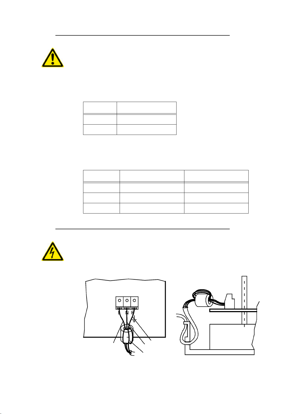
5.4 Connection of the mains input
ATTENTION:
High voltage. Mains voltage
The powercord must be connected to the terminal X1. To prevent interfe-
rences it must be looped through a ferrite-filter as shown in Figure 10:
Table 1: Transformer connection secondary side
Terminal Colour
X10.1 Green
X10.2 Red
Table 2: Trafoanschluss Primärzeitig
Terminal Colour for 220V Colour for 110V
X6.1 Orange Orange + Brown
X6.2 Red + Brown nc
X6.3 Black Red + Black
Figure 11: Mains connection
Brown Yellow/Green
Blue
Ferrit-Filter
IN
X1

5999.505-01C 12.06.2007 WM 215
5.5 Connection of the frontpanel
The frontpanel must be connected as shown in Figure 12:
5.6 Grounding of the labeler
The grounding of the module rail and of the adapter must be done to terminal
X2. See also Figure 12.
5.7 Motor and motorcable
Attention:
•The motor never must be dismantled !
•Steppermotor heats up during operation !
•When connecting or disconnecting the motor, the labeler must be
switched off !
•While working on the motor, the labeler must be disconnected from
mains!
Figure 12: Frontpanel connection
Brown
Blue
Brown/White
Ground
X2
X4 X5
X3
F1

5999.505-01C 12.06.2007 WM216
The motor is connected inside of the labeler. The motorcable is lead through
the hole in the middle part of the board. See Figure 13:
The motorwires are connected to the terminal X12. The mode connecting the
orange and black wire determines the turning direction of the stepping motor.
See also table below:
Table 3: Motor connection
Terminal Left Right
X12.1 Black Green Orange Black
X12.2 Orange Black Black Green
X12.3 Red Blue Red Blue
X12.4 Yellow Red Yellow Red
Figure 13: Motor connection
X12
1 2 3 4
Red / Blue
Yellow / Red

5999.505-01C 12.06.2007 WM 217
6Software
After turning on the labeler, the input signals are scanned to start a labeling
cycle.
The dispensing of a label is triggered by the negative edge of GSC (Goods
scanner input). The stop of the labelling is triggered by the detection of the
gap (LSC) and performing the remaining steps for the predispensing.
The timing diagram of the signals is shown in Figure 14:
1. Length of the predispensing
If the signal FEED is active the motor is turning. The FEED signal has no
electrical tabs on the Collamat 2600 terminals.
If the predispensing is increased, it is executed immediately. If it is reduced,
it is executed after dispensing the next label.
To generate the holding torque, the motor is powered all the time.
If, for any reason, no negative edge is detected on the LSC-input, the label-
web is automatically stopped after approximately 0.75 meters.
The stepper motor is driven by a sinusoidal corrent figure.
The minimum speed is 3 m/min. The maximum speed is 15 m/min.
Figure 14: Timediagram of the signals GSC, LSC and FEED
Signal
GSC
LSC
FEED
1
t

5999.505-01C 12.06.2007 WM218
7Trouble shooting
7.1 Fuses
The Collamat 2600 contains three fuses:
To exchange the fuses, the cover of the Collamat 2600 must be removed. If
the fuse of the main voltage is blown, the indicator lamp of the power switch
is not illuminated when the Collamat 2600 is switched on.
ATTENTION:
If the dispenser board is defective, it must be exchanged. Any repairs
ormodifications notmadeby HMCollamat AGwillexpire theguarantee.
Table 4: Sicherungen
Fuse Voltage Value Part. No.
F1 110V:
230V: Mains voltage 4AT; 5*20mm
2AT; 5*20mm 74030800
74030341
F10 Motordriver 3.15T; 5*20mm 74031216
F11 Logic 12 V, 5V 1AT; 5*20mm 74030755

5999.505-01C 12.06.2007 WM 219
8Peripheral units and sensors
8.1 Optical label scanner
The colours ar assigned as follows:
Table 5: Colurs of the LSC & TCY wires
Signal Colour
+12V (LSC) Green
LSC White
GND Brown
+12V (TCY) Green
TCY Brown
Figure 15: Optical label scanner
Labelscanner
+12V
LSC
GND
5
9
1
Transparency
+12V
TCY
5
1

5999.505-01C 12.06.2007 WM220
8.2 Goods scanner NPN
8.2.1 Connecting the goods scanner
The goods scanners is connected to the GSC1connector. Figure 17 shows
the connection of the standard HM Collamat AG IR goods scanner:
Figure 18 shows the connection of a NPN-scanner:
Figure 16: NPN-Reflective scanner
Goodscanner
+12V
GSC
GND
NPN
Figure 17: Connection of the CS IR goods scanner
GND
GSC+
12V
GND
LSC
12V
TCY
12V
bn
gn
bn
ws
gb
gn
GND
+12V
GND
GSC1
+12V
IR
Figure 18: Connection of a NPN-scanner
GND
GSC+
12V
GND
LSC
12V
TCY
12V
GND
GSC1
+12V
NPN
Table of contents


