The above-said operations must be carried out only by qualied technicians.
DESCRIPTION
This solenoid valve is made to guarantee the gas interception either for gas detector signals
(methane, lpg, carbon monoxide and so on) and safety thermostats, or for an electric black out.
In order to be more reliable this solenoid valve can be reset only when electrically supplied and
only if the gas detector doesn’t send any danger signal.
Simply powering the coil does not open the valve. The reset mechanism has to be operated
by hand (see MANUAL RESET).
INSTALLATION
The solenoid valve is in conformity with the Directive 94/9/CE (said Directive ATEX 100 a) as device
of group II, category 3G and as device of group II, category 3D. For this reason it is suitable to be
installed in the zones 2 and 22 as classied in the attachment I to the Directive 99/92/EC.
To determine the qualication and the extension of the dangerous zones, see the norm EN 60079-10.
The device, if installed and serviced respecting all the conditions and the technical instructions of
this document, is not source of specic dangers: in particular, during the normal working, is not
forecast, by the solenoid valve, the emission in the atmosphere of inammable substance in way
to cause an explosive atmosphere.
WARNING: all installation/wiring/maintenance work must be carried out by skilled
staff.
• The gas supply must be shut off before installation.
• Check that the line pressure DOES NOT EXCEED the maximum pressure stated on the product
label.
• They are normally installed upstream of the regulator devices and must be installed with the
arrow (on the body of the device) facing towards the user appliance. They will function equally
effectively if installed vertical. They must not be installed upside down (with the coil underneath).
• During installation take care not to allow debris or scraps of metal to enter the device.
• If the device is threaded check that the pipeline thread is not too long; overlong threads may
damage the body of the device when screwed into place. Do not use the coil for leverage when
screwing into position; use the appropriate tool. Assemble pipe and ttings which are consistent
with solenoid valve connection threads.
• If the device is anged check that the inlet and outlet counteranges are perfectly parallel to
avoid unnecessary mechanical stresses on the body of the device. Also calculate the space
needed to t the seal. If the gap left after the seal is tted is too wide, do not try to close it by
over-tightening the device’s bolts.
• Always check that the system is gas-tight after installation.
ELECTRICAL CONNECTIONS
• Before making electrical connections, check that the mains voltage is the same as the power
supply voltage stated on the product label.
• Disconnect the power supply before wiring.
• Wire the connector with H05RN-F 3X0.75mm² cable outside Ø from 6.2 a 8.1mm, taking care to
ensure that the device has IP65 protection.
• Use cable terminals when wiring the connector (see g. 4).
• Connect the power supply to terminals 1 and 2 and the ground wire to terminal .
The coil is also suitable for permanent power supply. In case of continuous duty, it is absolutely
normal for the coil to heat up.
The coil should not be touched with bare hands after it has been continuously powered for more
than 20 minutes. Before maintenance work, wait for the coil to cool or use suitable protective
equipment.
In the case the valve is equipped with the CPI SWITCH (picture 3) make the connections
complying with the coloring wires indicated here below:
• black wire: common
• red wire: signal with the microswitch at rest (the valve is open)
• white wire: signal with pushed microswitch (the valve is closed)
it is suggested to reset and close twice/thrice the valve (removing voltage) to check the proper
CPI switch signal.
For any problems or information concerning installation/wiring/maintenance
operations, see address and telephone numbers on the back page.
EXAMPLE OF INSTALLATION
1. GCR manual reset solenoid valve
2. SM series jerk handle ON/OFF valve
3. FRG/2MC series lter pressure regulator
4. Manometer
5. Gas detector
6. Lever for remote SM ON/OFF valve control
TECHNICAL DATA
• Use : not aggressive gases of the three families (dry gases)
• Environment temperature : - 20°C + 60°C
• Max supercial temperature * : 80 °C
• Power supply voltage : 12 Vdc, 12 V/50 Hz, 24 Vdc, 24 V/50 Hz, 110 V/50-60 Hz, 230
V/50-60 Hz
• Power supply voltage tolerance : -15% ... +10%
• Power absorption : see table
• Max. working pressure : 500 mbar
• Closing time : < 1 s
• Degree of protection : IP65
• Class : A
• Group : 2
• Threaded connections Rp : (DN 15 ÷ DN 50) according to EN 10226
• Threaded connections NPT : on request
* The maximum supercial temperature is calculated powering the solenoid valve at the nominal
tension increased of 10% and at the maximum environmental temperature.
CPI SWITCH TECHNICAL DATA
• Switching voltage : max 250 V (Vac)
• Switching current : max 2 A
• Degree of protection : IP67
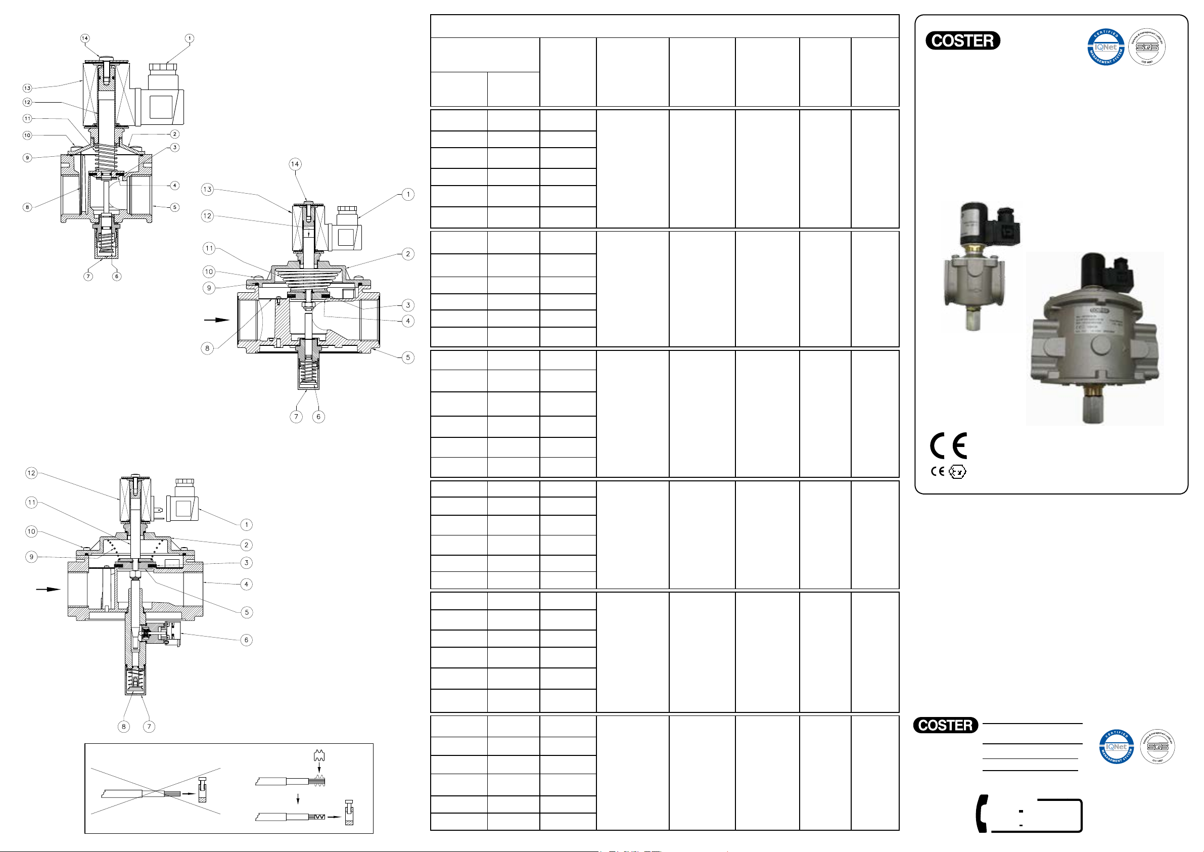
MANUAL RESET (see g. 1 and 2)
To reset the solenoid valve, pay attention there is tension and unscrew completely the possible
protective small cap.
Close the ow downstream the solenoid valve to grant the pressure balance between upstream and
downstream during opening.
Push the reset handgrip (6) and wait for an istant the balance between the inlet and outlet pressure
of the valve up to the hooking.
Rescrew in the original position the protective small cap and possibly seal it in that position.
SERVICING (see g. 1 and 2)
In all cases, before performing any internal checks make sure that:
1. the power supply to the device is disconnected
2. there is no pressurised gas inside the device
unscrew by a screwdriver the xing screws (9) and, with care, take the cover (2) off the body (5) of
the valve, then control the obturator and if it is necessary change the rubber made seal component
(3). Then clean or blow the lter (16) or change it if necessary; then assemble doing backward the
same operation.
pipe user
Overall dimensions in mm
Connections A B C
GCR DN 15 70 163 70
GCR DN 20 70 163 70
GCR DN 25 70 163 70
GCR DN 32 160 215 140
GCR DN 40 160 215 140
GCR DN 50 160 245 140
LOAD LOSS DIAGRAM
1) methane
2) air
3) town gas
4) lpg
Diagram calculated with P1 = 50 mbar