manuals.online logo
Brands
  1. Home
  2. •
  3. Brands
  4. •
  5. Coster
  6. •
  7. Modem
  8. •
  9. Coster GSM 714 User manual

Coster GSM 714 User manual

1
We reserve the right to make changes without notice
T 335 - GSM 714 Eng. 12.01.10 MM REV. 01
T 335
12.01.10 MM
REV. 01
GSM 714 Eng.
1. APPLICATION
GSM 714 modem can be used in the central control station for data transmission in TELECOSTER telemanagement
systems.
2. FUNCTIONS
GSM 714 is a GSM dual band modem (900/1800MHz) with a transmission speed adjustable from 1200 to 9600
bps in non-transparent mode (with error correction). It supports AT + controls in conformity with ETSI GSM 07.07
standard.It incorporates a self-diagnosing function that indicates the presence of GSM signal.The digital interface
conforms to USB specification 1.0.
3. REFERENCE STANDARDS
GSM modem conforms to current legislation relating to Directive R&TTE99/5/CE and, in particular, to the following
regulations :
– Health & Safety (Art. 3.1a): EN60950:2000.
– EMC (Art. 3.1b): EN 301 489-7 v1. 2.1 (08/2002).
– RF spectrum efficiency (Art. 3.2): 3GPP TS 51.010-1, v.5.1.0 (12/2002)
– EN 301 511.v9.0.2 (final draft).
4. TECHNICAL DATA
• Electrical & mechanical:
Power supply : via USB interface
Protection IP 40
Construction standards See point 3
Ambient temperature:
operating – 20 ÷ + 55 °C
storage – 25 ÷ + 70 °C
Dimensions 65 x 80 x 18 mm (L x P x H)
Weight 53 g
• Transmission data :
Data format asynchronous start-stop
Character format 7/8 bit data, 1/2 stop bit,
parity odd/even/none
Transmission speed 1,200…9,600 bps
Transmission standard V.22bis, V.32, V.110
Transmission mode full duplex
Interface speed standard USB 1.0
Data Terminal Equipment interface USB Mini-B
Data Terminal Ready management OFF status of DTR prevents
tr transmission/reception by modem
Traffic control RTS/CTS
RF power output (max) 2W per GSM900
1W per GSM1800
RF antenna incorporated
• Uses GSM 900/1800 MHz digital communication networks.
• RF dual band antenna incorporated.
• Supplied with :
– 1 USB cable
– CDROM with driver
GSM MODEM FOR LAPTOP PCs
WITH USB PORT
WARNING: do not use this Modem for fixed central Remote Management control stations, but
only for temporary stations with a laptop PC.
Exposed to electrical disturbances, USB ports may unconfigure and block Remote
Management, requiring reconfiguration.
2We reserve the right to make changes without notice
T 335 - GSM 714 Eng. 12.01.10 MM REV. 01
5. CONNECTIONS
5.1 USB connector
USB cable supplied for connecting modem to PC.
WARNING: connect the modem directly to the PC port; do not use USB port duplicators or USB hub.
6. SIM CARDS
6.1 Purchase of SIM card.
You are advised to purchase the SIM card from your chosen GSM network service provider for business networks.
When purchasing, it is essential to request a card enabled for the transmission and reception of DATA with the following
communication modes: AUTOBAUDING; ASYNCHRONOUS; NOT TRANSPARENT (correction data enabled).
6.2 Inserting SIM card in GSM 714
Before inserting the SIM card in the modem it is essential to disable the PIN code of the card and any operator ser-
vices that might interfere with the telemanagement (e.g. answering service, call forwarding).
To do this, use a GSM cellular telephone and insert the SIM card in it; then, following the instructions received from
this telephone, disable the PIN code. To disable the answering service, etc, ask the telephone operator.
The operations required to install the SIM card in GSM 714 are as follows:
– Ensure that the modem is switched off, then disconnect the USB cable. You must NOT insert or remove
the SIM card while the modem is switched on.
– Using something pointed, press the yellow button to extract the card holder.
– Insert the SIM card in the holder making sure that it is the right way round.
– Push in the card holder until it clicks into place.
3
We reserve the right to make changes without notice
T 335 - GSM 714 Eng. 12.01.10 MM REV. 01
6.3 GSM network signal strength indicator
The red LED indicates the status of the radio module :
– always off : modem not powered;
– rapid flashing : SIM card not inserted or searching for signal;
– brief flash : signal present, modem not transmitting;
– always lit : modem transmitting or connected to telephone line.
The green LED indicates the status of the USB line :
– always off : no USB/serial activity;
– flashing : passage of data on USB/serial line;
To know exactly the signal quality you must:
– using a communication program or SWC 701 telemanagement program, send instruction “AT + CSQ” to the
modem;
– read the reply coming from GSM 714 :
- from 14 to 31 = signal should be sufficient..
- from 0 to 13 and +99 = signal unlikely to be sufficient.
6.4 Installation of modem by means of CDROM on a PC on which already installed SWC701 software
WARNING:
•Do not use USB via hub but connect the modem directly to the USB output of the PC
• If modem is connected to a portable PC you are advised not to activate the energy-saving option because
when PC re-started the modem may not re-start. In this event, reboot the system.
• During the installation procedure, connect the modem to the PC ONLY when requested and not before.
Installation procedure:
• Install the SIM card as at point 6.2.
• Insert the CDROM, press INSTALL and follow the procedure.
• Only when requested, connect the modem to the PC via the USB cable supplied.
• Re-boot the PC.
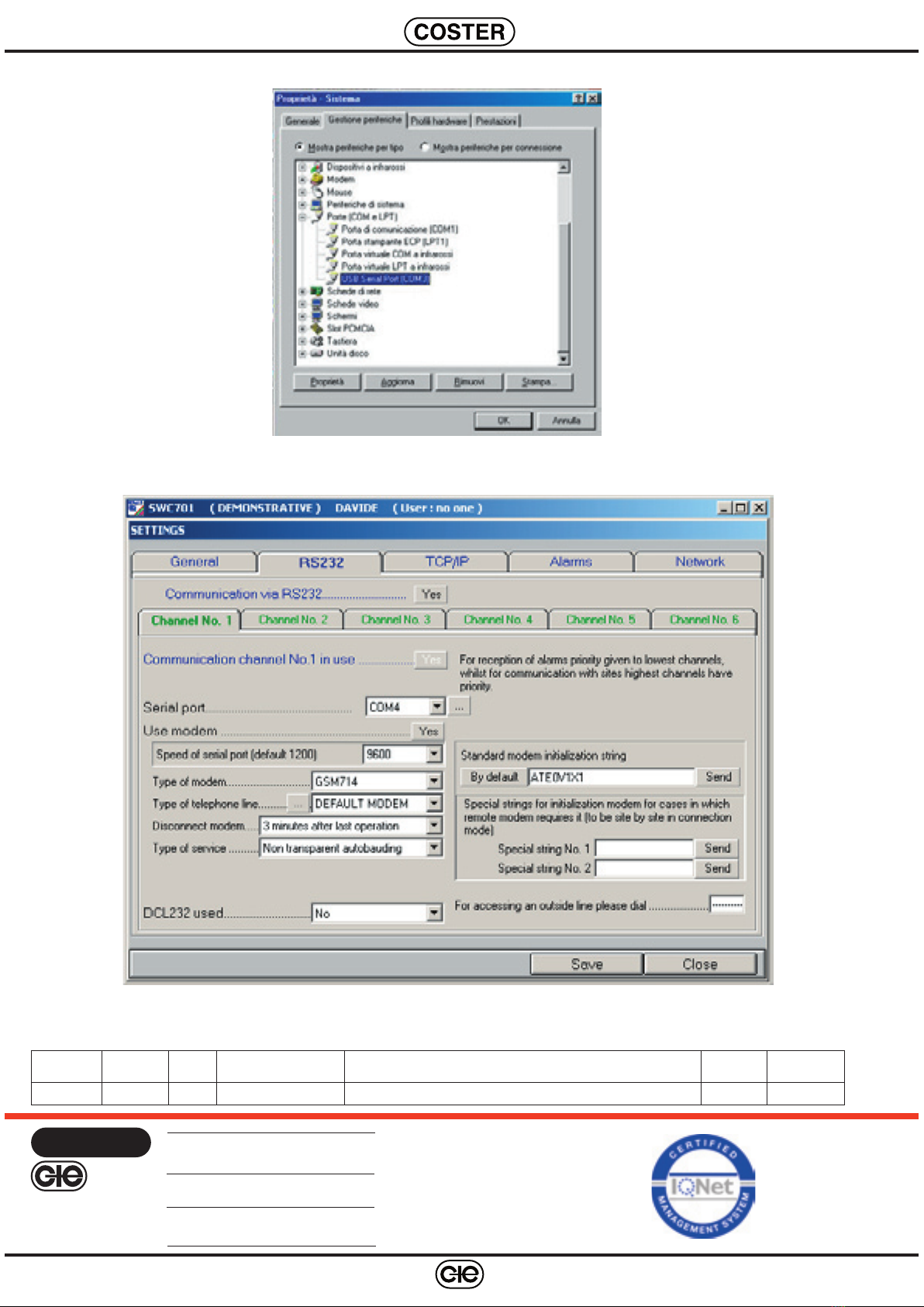
• Once the PC has finished booting, identify the COM port associated with GMS 714 modem by means of the
system properties window (6.5) from the Windows™ control panel.
The number of the COM port is found in the list of the ports (COM and LFT) under the heading “USB Serial
Port (COMX)”.
"X" is the number of the COM port associated with GSM 714 modem: make a note of this number .
If, for example, you find “USB Serial Port (COM3)” in the list, this means that the virtual serial port COM3 is
the one which must be used to converse with modem GSM714.
• Run software SWC701 (version later than v. 0.90.1983), go to “Settings” (6.6) and configure the GSM714
modem at the COM port previously identified.
Red LED
Green LED
4We reserve the right to make changes without notice
T 335 - GSM 714 Eng. 12.01.10 MM REV. 01
D 33317
6.5 “System properties” – Control Panel - Windows™
6.6 “Settings” – SWC 701 (Version later than 0.90.1983)
COSTER TECNOLOGIE ELETTRONICHE S.p.A.
Sede Legale: 20132 Milano - Via San G.B. De La Salle, 4/a
E-mail: [email protected] Web: www.coster.eu
COSTER
CONTROLLI
TEMPERATURA
ENERGIA
Head Office & Sales
Via San G.B. De La Salle, 4/a Tel. +39 022722121
20132 - Milano Fax +39 022593645
Orders Fax +39 0227221239
Reg. Off. Central & Southern
Via S. Longanesi, 14 Tel. +39 065573330
00146 - Roma Fax +39 065566517
Shipping
Via Gen. Treboldi, 190/192 Tel. +39 0364773200
25048 - Edolo (BS) Tel. +39 0364773202
Modifiche scheda
Data Revisione n. Pagina Paragrafo Descrizione modifiche Versione
Firmware
Versione
Software
12.01.10 AM 01 1 Note Add note for the correct use of modem

Other Coster Modem manuals

Coster GSM 822 User manual

Coster

Coster GSM 822 User manual

Coster GSM 622 User manual

Coster

Coster GSM 622 User manual

Popular Modem manuals by other brands

SCS PTC-IIIusb user manual

SCS

SCS PTC-IIIusb user manual

Arris Touchstone TM1602G user guide

Arris

Arris Touchstone TM1602G user guide

Navini Networks Ripwave 2300E/U user guide

Navini Networks

Navini Networks Ripwave 2300E/U user guide

NetComm NF8AC quick start guide

NetComm

NetComm NF8AC quick start guide

Comnet netwave NW1 Installation and operation manual

Comnet

Comnet netwave NW1 Installation and operation manual

Vernier VE user manual

Vernier

Vernier VE user manual

NetComm NB100 quick start guide

NetComm

NetComm NB100 quick start guide

Ebyte E32-DTU(900L300)-V8 user manual

Ebyte

Ebyte E32-DTU(900L300)-V8 user manual

Moxa Technologies NPort Express user guide

Moxa Technologies

Moxa Technologies NPort Express user guide

Huawei E3372 quick start

Huawei

Huawei E3372 quick start

Sierra Wireless AirCard USB 309 quick start guide

Sierra Wireless

Sierra Wireless AirCard USB 309 quick start guide

Assured Wireless AW12 HPUE manual

Assured Wireless

Assured Wireless AW12 HPUE manual

Sierra Wireless AirPrime MC8775 Reference manual

Sierra Wireless

Sierra Wireless AirPrime MC8775 Reference manual

Huawei E3531 manual

Huawei

Huawei E3531 manual

Dynalink RTA100+ user manual

Dynalink

Dynalink RTA100+ user manual

Paradise Datacom P300 Series Installation & operating handbook

Paradise Datacom

Paradise Datacom P300 Series Installation & operating handbook

Beeline 3G USB Modem user guide

Beeline

Beeline 3G USB Modem user guide

NETGEAR DGFV338 - ProSafe Wireless ADSL Modem VPN Firewall... Reference manual

NETGEAR

NETGEAR DGFV338 - ProSafe Wireless ADSL Modem VPN Firewall... Reference manual

manuals.online logo
manuals.online logoBrands
  • About & Mission
  • Contact us
  • Privacy Policy
  • Terms and Conditions

Copyright 2025 Manuals.Online. All Rights Reserved.