3
T 330 - GSM 822 Eng. 10.12.01
We reserve the right to make changes without notice
COSTER
8. INSTALLATION & CONNECTIONS
Themodemmustbesitedinadryspacewithatemperaturenotabove55°Candprotectedfromanypossiblewater
leaks.
It must be mounted on a wall with the antenna sited in a zone covered by the telephone network provider chosen:
• Ensure that the wall where the modem is to be mounted is in a zone covered by the chosen network provider.
This can be checked by locating a phone in the proposed position & checking the on screen display for signal
strength. Should there be no signal, try mounting the modem on another wall, or arrange for the antenna to be
installed in a different place from the modem using a suitable extension.
• Unscrew the four screws (6.12) that secure the cover to the base and separate the two parts.
• Fix the modem to the wall using the holes provided (6.11).
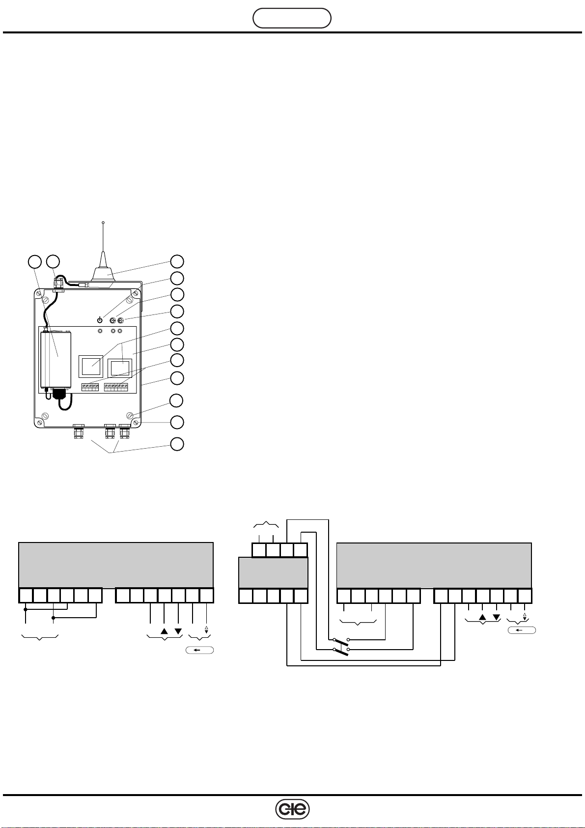
• Carry out the electrical connections strictly in accordance with the wiring diagrams given above and with the
regulations in force, using PG7 cable entry glands (6.2) .
• It is advisable not to insert more than two cables in a single terminal of the modem.
• For the power supply connections to the modem the use of stranded copper cables of at least 1.5 mm2cross
section is recommended.
•For thecommunication ring(C-Bus) use anormal twin-corecable ofat least1mm2crosssection;it isimportant to
respect the polarities and to this end it is advisable to use wires having different colours.
• Check with a multimeter that there are no short circuits or breaks in the power wiring or C-Bus circuit.
• Power up (230V~) and check with a multimeter across terminals L - N and L1- N1.
• Remove power, replace cover on base and secure it with the four screws (6.12).
9. SIM CARDWARNING: whenordering theGSM 822modem thename ofthe telephonenetwork providerto beused shouldbe
specified so that the modem is configured correctly on delivery.
• Purchase of SIM card
It is advisable to purchase your SIM card from your chosen GSM network service providers’ agent.
When purchasing it is indispensable to:
– ask for a card enabled for the transmission and reception of data and fax.
Usually, the telephone operator will supply a SIM card with three telephone numbers:
- a VOICE number to be used for voice telephone calls.
- a FAX number to be used for fax communication.
- a DATA number to be used for telemanagement.
– ask for the following modes for communication data:
- Asynchronous – “TRANSPARENT” (error correction disabled).
- Asynchronous – “NON TRANSPARENT” (error correction enabled)
Note: ItmaybepossibletoobtainaSIMcardwithonenumber(only dataservicesenabled). Contactyournetwork
provider for details.
• Inserting the SIM card in GSM 822
WARNING : Before inserting the SIM card in GSM 822 modem it is indispensable to disable the PIN code of the
card.
TocarryoutthisoperationuseaGSMcellulartelephone:inserttheSIMcardconcernedinthecellular
telephone and then, following the instructions for this telephone, disable the PIN code of the SIM
card.
The operations to be carried out to install the SIM card in GSM 822 are:
– ensure that the GSM 822 modem is switched off. UNDER NO CIRCUMSTANCES MUST THE SIM CARD BE
INSERTEDORREMOVEDWHILSTTHEMODEMISSWITCHEDON. THESEOPERATIONSMUSTBECARRIED
OUT WITH THE MODEM SWITCHED OFF.
– removethetransparentcoverbyfirstunscrewingthefourscrews(6.12)thatsecureittothebaseandseparatethe
two parts.
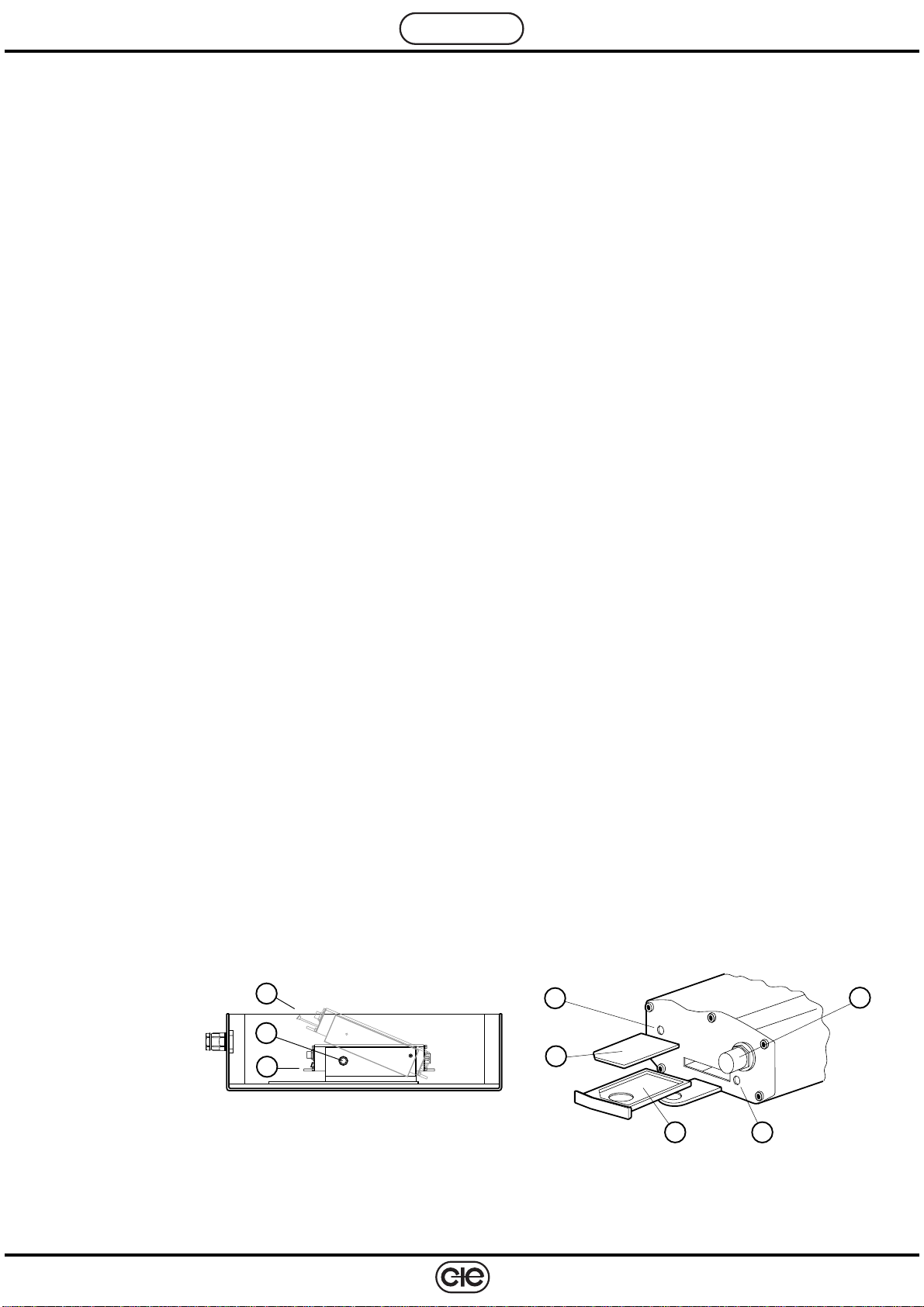
– loosenthesecuringscrew(9.3)and,usingthefingerofonehand,liftupthemodemsoastobeabletoaccessthe
front panel of the device (as shown in 9.1and 9.2).
– using a pointed object, press the yellow button (9.8) in order to extract the holder for the SIM card.
– insert the SIM card in the holder provided making sure that the card is the correct way up.
– re-insert the card holder in the modem and switch on the power.
antenna
side
1-normal position of GSM 822
2-raised position of GSM 822
3-modem securing screws
4-holder for SIM card
5-SIM card
6-red LED indicates when GSM carrier detected
7-antenna connector
8-yellow button for extracting SIM card holder
1
2
3
84
5
67