Cotek CT Series User manual

User Guide For CT Series
3. Mechanical dimension
MODEL: CT-201 MODEL: CT-204
Unit: mm
MODEL: CT-251 MODEL: CT-551
1. Features
• Support COTEK Programmable Series power supply (Excluding AK & AEK-3000 ORing Series)
• Support max. 8 units parallel control function
• Support RS232/485 protocol
• Easy installation for parallel control.
2. Specification
• Input Voltage: 5Vdc
• Operating Temperature Range: -10℃ ~ 60℃
• Storage Temperature Range: - 30℃~ 70℃
• Baud rate: 4800, N, 8, 1
• Connector: DB-9F fo RS232, RJ-11 (6P4C) for RS485
• Optical Isolation: I/P - O/P: 2500Vac rms for 1 minute
71.5
45 1610.5
3.75
3.75
3.75 4 - Ø3
4 - Ø3
32.5
25
CN2
5
4
3
2
1
23 1
JP4
15
9 6
CN1
CN2
CN1
CN2
CN3
CN3
MAX 3mm
14
4 - Ø3
120
110 55
4.5
MAX 3mm
14
45
3010.5
CN1 CN2 CN3 CN4
CN5
CN6
CN7
15
69
JP2
JP1
JP3
JP4
23 1 23 1 23 1 23 1
5
4
3
2
1
23 1
MAX 3mm
14
71.5
1610.5 45 3.75 16
3.75
40
47.5
32.5
15
9 6
J1
J1
10.5 45
71.5
1
6
CN4
1
6
CN3
4 - Ø3
14
MAX 3mm
25
3.75
CN1
5
4
3
2
1
23 1
1

6P4C
12.4±0.3 14.6±0.3
3.1±0.2
12.4±0.3
6.5±0.2
9.6±0.2
CONDUCTOR
14.6±0.3
6.5±0.2
30cm
3.1±0.2
9.6±0.2
6
1
6
(2) (2)
(1)
INSULATION
JACKET
A B
1
DO NOT use standard telephone cable.
WARNING!
4. CT cable drawing
12
2324
12
2324
200
200
P1
12
2324
P1
P2
1 2
23 24
P2
Mating Housing / Contact
JST PHDR-24VS
or equivalent
JST
SPHD-002T-P0.5
or equivalent
Mating Housing / Contact
JST PHDR-24VS
or equivalent
JST
SPHD-002T-P0.5
or equivalent
• CT-201 / CT-204 Cable
(COTEK Part no.47-0124-0001)
• CT-251 / CT-551 Cable
(COTEK Part no.47-0112-0021)
• CT
parallel cable (For CT-551 Only)
(COTEK Part no. 47-0106-0003)
CT-251 / CT-551
CT-251 / CT-551
2
WARNING!

• CT-204 to CT-204 parallel
cable
(Optional)
(COTEK Part no. 47-0103-0028)
5. Accessories
6. Pin assignment
1
3
4
5
6
2
DATA +
DATA -
+5V
NC
GND
•
DB-9F RS232 (only for CT-201/204/251)
•
RJ-11 6P4C RS485 (only for CT-251/551)
1
3
4
5
6
2
NC
TxD
NC
NC
7
8
NC
NC
9NC
RxD
RS485
1 6
RJ-11 6P4C
GND
NC
16
CT board MALE D-SUB FEMALE D-SUB
TO PC RS-232
5: VCC
CABLE
3: RXD
2: GND
4: TXD
8:
6: DSR
4: DTR
3: TXD
2: RXD
5: GND
7:
: VCC
CT-201
MODEL
CT-204
CT-251
CT-551
User Guide
CT parallel
cable
EC350R-05P
connector
CT-204 to CT-204
cable
CT-201 / CT-204
cable
CT-251 / CT-551
cable
Accessories
1
1
1
1
1
4
1
1
---
---
---
---
---
---
---
1
---
Optional
---
---
1
---
1
1
300mm ±5
3

7. CT Series Quick Feature Guide
CT-201
MODEL
Function
CT-204
CT-251
CT-551
Parallel /
Remote sense Power
Connection RS485
Expansion RS232
Expansion
4 Units
1 Unit
1 Unit
1 Unit
To Host
RS-232(DB-9F)
RS-232(DB-9F)
---
RS-232(DB-9F)
1
3
4
5
2
GND
PAR
VS -
VS +
AUX
•
ECH350V-05P DINKLE (only for CT-201/251/551)
1
3
2
GND
TxD
RxD
•
B-XH-A 180’C (only for CT-204)
Pin No.
1
2
3
4
5
Pin No.
6
7
8
9
10
Pin No.
12
13
14
15
Pin No.
16
17
18
19
20
AssignmentPin No.
21
22
23
24
NC.
NC.
AUX
GND
Assignment
VSET
GND
EN-
GND
PAR
Assignment
POK
VO+
VS-
VO-
VS+
Assignment
SDA
SCL
GND
GND
Assignment
GND
AUX
VCI
ACI
EN+
•
Control Pin connections: JST S24B-PHDSS or equivalent
11
123
1 2 3 4 5
AUX
4

8. Application Notes
MODEL: CT-201
1
CN2
CN1
CN3
15
6
9
23
1
2
3
4
5
+
-
Load
+
-
PC
RS232
MAX. 10M
0
7
6
5
4
3
2
1
DC OUTPUT
CN2
Programmable
Power Supply
CT-201
MAX. 200mm
(47-0124-0001)
5

CN1
JP1
JP3
JP4
CN6
CN7
CN5
1
151
1
23
Load
+
-
CN2
123
CN3
123
CN4
123
JP2
CT-204
+
-
DC OUTPUT
+
-
+
-
+
-
CN2 CN2
RS232
0
7
6
5
4
3
2
1
0
7
6
5
4
3
2
1
0
7
6
5
4
3
2
1
0
7
6
5
4
3
2
1
CN1
JP1
JP3
JP4
CN6
CN7
CN5
1
151
1
23
CN2
123
CN3
123
CN4
123
JP2
CT-204
+
-
+
-
+
-
+
-
RS232
PC
MAX. 10M
0
7
6
5
4
3
2
1
0
7
6
5
4
3
2
1
0
7
6
5
4
3
2
1
0
7
6
5
4
3
2
1
DC OUTPUT DC OUTPUT DC OUTPUT
CN2 CN2
CN2 CN2CN2 CN2
DC OUTPUT DC OUTPUT DC OUTPUT DC OUTPUT
Programmable
Power Supply
Programmable
Power Supply
Programmable
Power Supply
Programmable
Power Supply
Programmable
Power Supply
Programmable
Power Supply
Programmable
Power Supply
Programmable
Power Supply
MODEL: CT-204 Control 8 EUT in parallel condition.
MAX. 200mm
(47-0124-0001)
MAX. 200mm
(47-0124-0001)
CT-204 to CT-204 parallel
cable
(47-0103-0028)
6

MODEL: CT-251 / 551 Parallel Control with Remote Sensing
1
+ +
-
CN2
+
-
DC OUTPUT
+
-
Load
+
-
CN2
J1
CN1
CN3
CN4
CN2
CN3
CN4
CN2
CN3
CN4
23
1
2
3
4
5
1
6
1
6
J1
CN1
123
1
2
3
4
5
1
6
1
6
J1
CN1
123
1
2
3
4
5
1
6
1
6
CN1
CN2
CN3
J1
1
5
CN4
6
9
123
1
2
3
4
5
1
6
-
MAX.8 EUT
*Last control board
J1 need short
MAX. 200M
(47-0106-0003)
MAX. 200M
(47-0106-0003)
MAX. 10M
MAX. 200mm
(47-0124-0001)
MAX. 200mm
(47-0124-0001)
MAX. 200mm
(47-0124-0001)
MAX. 200mm
(47-0124-0001)
RS485 RS485
CT-251CT-551CT-551CT-551
PC
4
0
7
6
5
3
2
1
CN2
DC OUTPUT DC OUTPUTDC OUTPUT
CN2 CN2
RS485 RS485 RS485 RS232
RS485
Programmable
Power Supply
Programmable
Power Supply
Programmable
Power Supply
Programmable
Power Supply
4
0
7
6
5
3
2
1
4
0
7
6
5
3
2
1
4
0
7
6
5
3
2
1
7

Before using RS232/485 to control COTEK programmable SMPS (excl. AK Series),
make sure to read the following notes:
1. Make sure the voltage and current setting has been correctly delivered to EUT before setting the
command (Power <type>) to turn on / off the power supply. If OVP, or OLP LED signal has been
activated due to incorrect operation, enter command POWER <type> will allow you to operate the
EUT and setting command.
2. Every RS232/485 command character must be entered within 400ms, the ending point is judged by
CR LF (0D0A), program will disregard the command if the command entering time exceeds 400ms
per character.
3. After shut-down of the power of EUT, command setting will return to default, local mode.
4. After power on the EUT with command execution complete, EUT will switch to remote mode with
orange LED signal status. For detail LED signal info, please refer to the EUT datasheet.
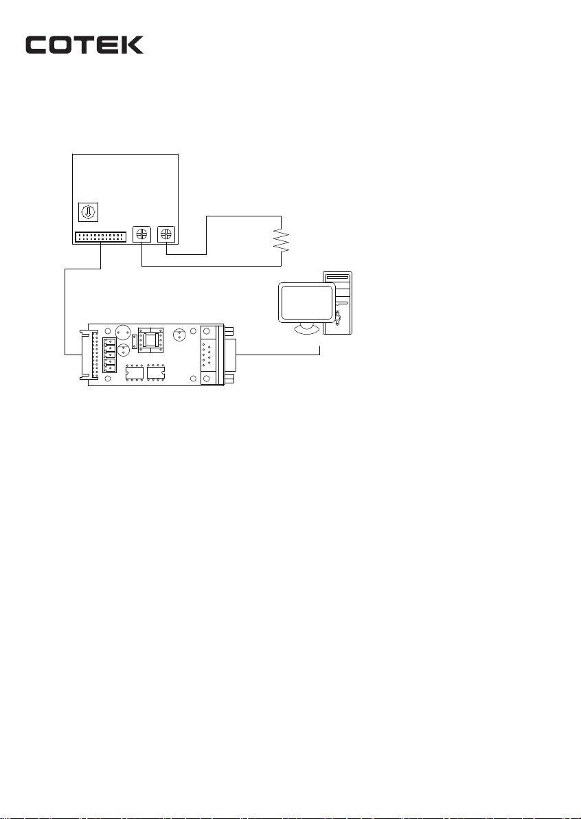
5. Please refer to the CT-xxx user manual (Page 02) for the cable spec. connect in between the CT-xxx
controller board and EUT. Make sure to connect the cable as instructed on the user manual to avoid
CT-xxx damage.
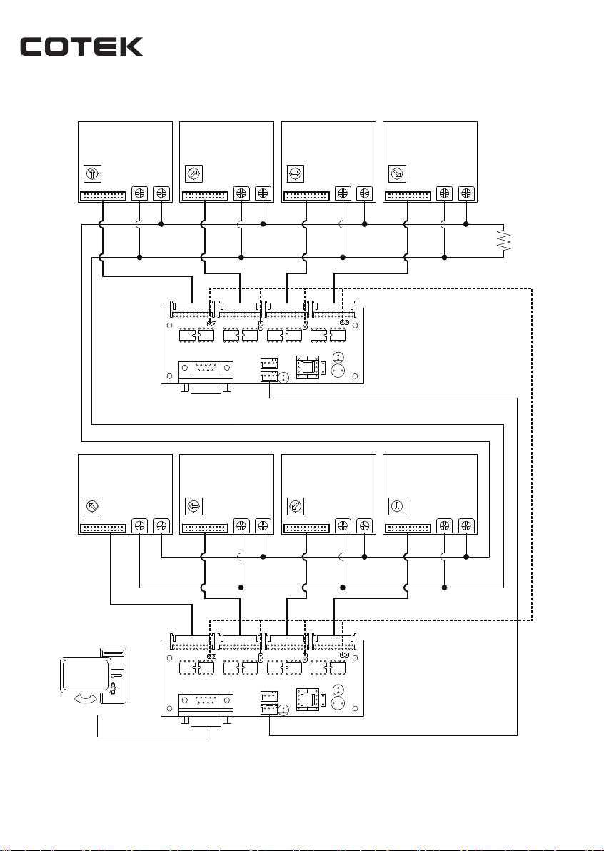
6. CT-xxx boards could support max. 8 units parallel control function (ADDS0-7). Before controlling the
EUT, make sure the address is not in conflict with each other.
7. When controlling multiple EUT’s, make sure to query the Address (ADDS x) first before entering
command to avoid EUT retrieving the incorrect value. If only single EUT, there is no need to query
ADDS before entering command.
No. 33, Sec. 2, Renhe Rd., Daxi District, Taoyuan City 33548, Taiwan
Phone : 886-3-33891999 FAX : 886-3-3802333
http : // www.cotek.com.tw
2022.04 A1
8
This manual suits for next models
4
Table of contents
Other Cotek Power Supply manuals
Popular Power Supply manuals by other brands

GenTran
GenTran Silent Generator Installation and operating manual

Manson Engineering Industrial
Manson Engineering Industrial KPS-6000 Series user manual

Ryobi
Ryobi EVERCHARGE P186 Operator's manual

BCP
BCP PUOOU1C1BK How to install

Korenix
Korenix DR-4524 Quick installation guide

Jackery
Jackery Explorer 700 Plus user manual