COTSWOLD CLUSTER-FLUSH User manual

CLUSTER-FLUSH
Milking Cluster Disinfection System
DOUBLE UP HI-LEVEL PARLOUR
Installation Instructions,
Sales & Service Information
Cotswold Dairy Equipment Co Ltd
Avenue 3 Station Lane Witney
Oxford OX28 4BP UK
Tel +44 (0)1993 774567
Fax +44 (0)1993 771776
e-mail sales@cotswold-dairy.couk
www.cotswold-dairy.com
MADE IN ENGLAND

AIR SUPPLY
CHEMICAL ENTRAINMENT
(option)
FLEXIBLE
PIPE
RUN
HEADER TANK
(Note: Level With Cylinders)
WATER INLET SYSTEM
CONNECTION TO MILK LINE (Y Piece)

COTSWOLD CLUSTER FLUSH
Milking Cluster Disinfection System
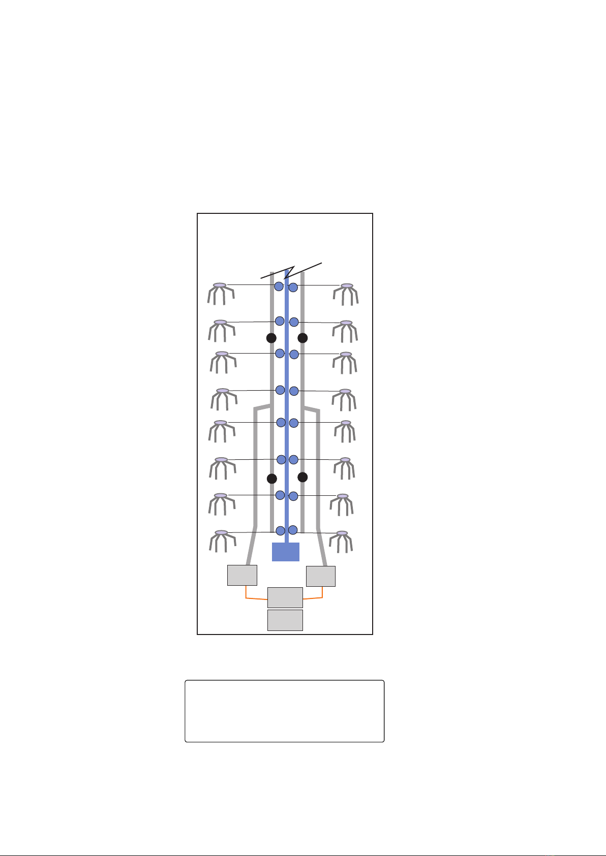
FOR SWING OVER PARLOURS
Model 220
PRODUCT MANUFACTURING, SERVICING & MAINTENANCE OVERVIEW
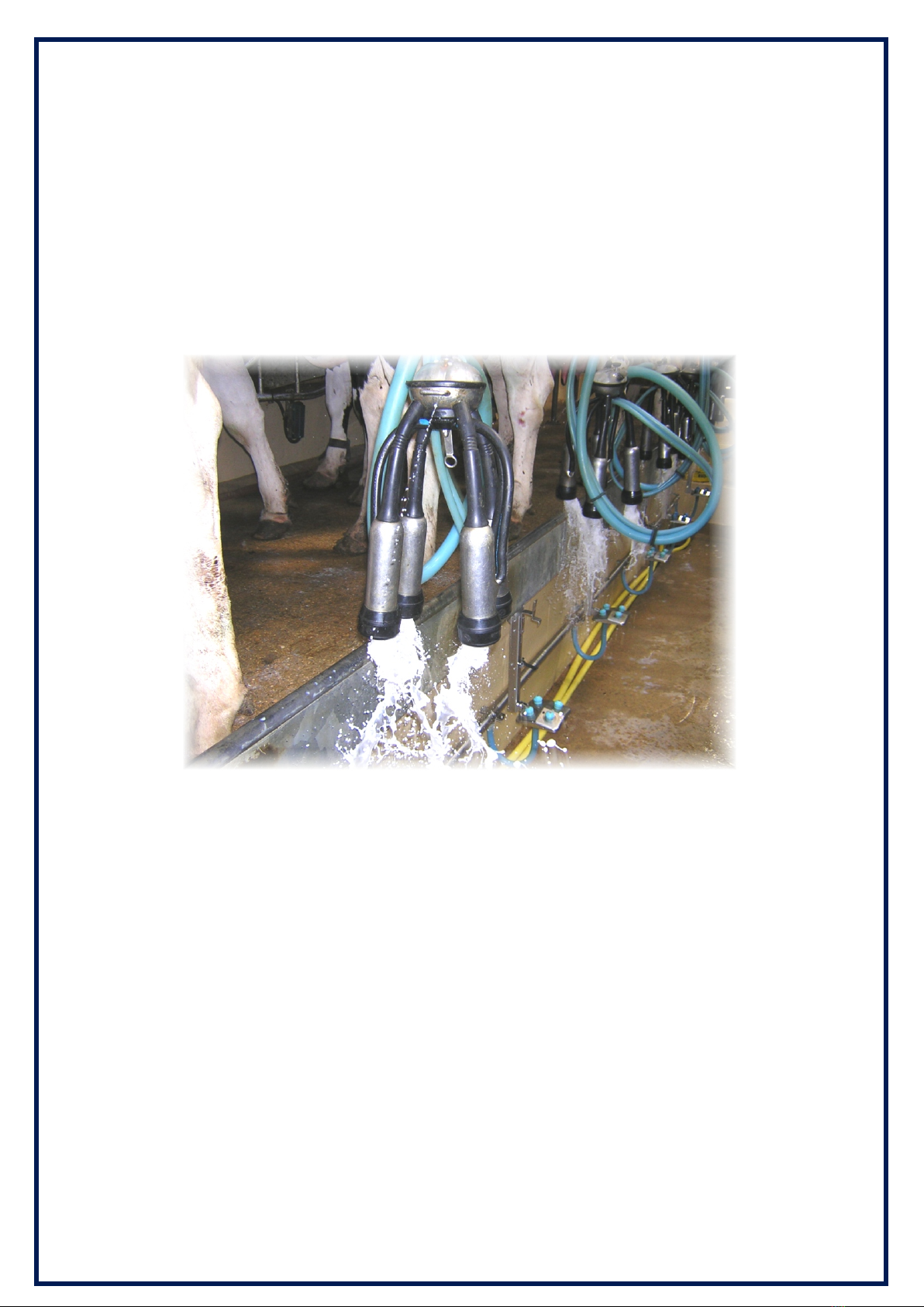
The Cotswold Cluster Flush is a system for the effective removal of infectious
material left in the milking cluster after a cow has been milked, so that the cluster
is disinfected before it is used to milk another cow.
The system mixes a small amount of recommended disinfectant with a pre-
determined amount of water, and automatically “flushes” each milking cluster with
this mixture. This process is repeated after every cow is milked.
Using the Cluster Flush System leads to a substantial reduction in the risk of
cross-infection between cows in the dairy.
SERVICES
The system is mains-powered (230v 50/60hz 1amp). At the point of use the
operating voltage is reduced to 24v dc.
The system requires a ready supply of fresh clean water and a clean compressed-
air supply (at 2 bar).
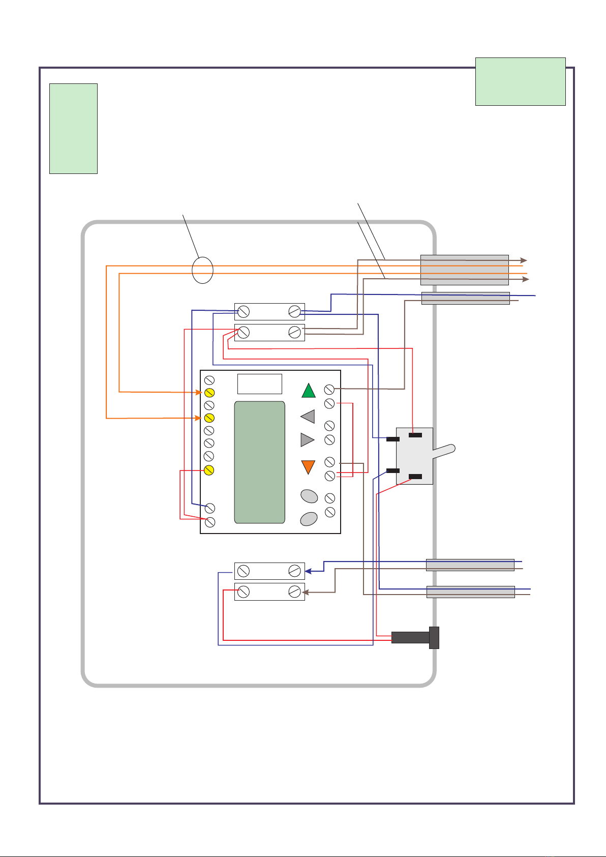
WIRING:
Connect the Power Supply Unit (PSU) to the mains via a double-pole isolation
switch, which should be visible and within easy reach of system operators.
Wiring from the power supply to each control box should be SELV, using a suitable
type of wire like H03VVF with a CSA of at least 0.75mm2.
All controllers and the power supply unit must be suitably earthed.
All connector tags and terminals will be zinc plated.
This equipment is rated for OV (over-voltage) Category 2 supplies.
PRESSURE VESSEL SPECIFICATION AND USAGE
The pressure cylinder is SEP-rated category-1 at its 2 bar mandatory operating
pressure. Its maximum safe pressure rating is 6 bar.
ENVIRONMENTAL CONDITIONS:
The system can be installed in milking parlours anywhere on the planet. Do not
use in the open, in direct sunlight or where pipework could be subject to freezing.
The protection offered by this product may be impaired or lost if installation and
maintenance is not carried out in line with the instructions in this manual.
LABELING
All labels used in this product comply with the CE Water and Hexane Rub Test. 3

CLUSTER FLUSH – PRODUCTION, SERVICING & MAINTENANCE
SAFETY INSTRUCTIONS –
(COMPLETE SYSTEM INCLUDING PRESSURE COMPONENTS)
(The Cotswold Cluster Flush – an SEP category 1 product)
These instructions relate primarily to factory manufacturing procedures, but since the
Cluster Flush needs regular onsite service and maintenance, we include them here too.
Component Preparation
All forming, bending drilling chamfering or any other working of
components must not cause changes in the mechanical characteristics of
those components and in no way reduce their efficiency.
Permanent joints in pressurised segments
For Cluster Flush pressure equipment (pressure cylinders), permanent
joining of components which contribute to their pressure resistance - and
components which are directly attached to them - must be carried out by
suitably trained personnel.
Permanent Joints and their adjacent zones must be free of any surface or
internal defects that could be detrimental to the safety of the equipment.
Permanent joints must always meet the minimum properties specified for
the materials to be joined.
Traceability
Inner pressure cylinders must be permanently labelled to show operating
pressure and year of manufacture.
Use label: (Pressure-Vessel (Sep-Category-1) , also label: (S Ayling materials
and date of moulding).
Final Testing
Pressure equipment must be subjected to final testing and inspection. A
test and inspection of the completed power supply unit and every control
panel/pressure cylinder assembly is essential.
IF IN DOUBT – ASK!
IEC 60417-5018)
CLUSTER FLUSH – PRODUCTION SAFETY INSTRUCTIONS.DOC
COTSWOLD CLUSTER FLUSH
Milking Cluster Disinfection System
4

COTSWOLD CLUSTER-FLUSH
Milking Cluster Disinfection System
FOR HIGH-LEVEL DOUBLE-UP PARLOURS:
DUAL
CONTROLLER
PSU
SOLENOIDS
SOLENOIDS
HEADER
OVERHEAD SCHEMATIC
(use in conjunction with attached
schematic side views)
WATER AIR
AIR
ANTI
SYPHON
VALVE
PERACETIC ACID CONCENTRATION
Set dosing at 0.5%
Usage @ Twice-A-Day Milking:-
0.7 Litres / 100 Cows / Day

INSTALLATION NOTES
(DOUBLE-UP PARLOUR HIGH LEVEL)
ORDER OF INSTALLATION
!For ease of installation, we recommend the following installation sequence:
! 1/ HEADER TANKS
2/ WATER / PLUMBING
3/ SET UP WATER CYLINDERS
4/ INSTALL AIRLINES
5/ CONTROLLERS and ELECTRICAL
WATER / CHEMICAL
Site the Header Tank at the same level as the cylinders. Ensure that the water level in the cylinders is
set 50mm (2 inches) below the top of the stainless tube, (see schematic drawings attached).
Run 2 inch (50mm) water tube from each header tank along the centre of the parlour, connecting to
each cylinder using tees, taps and 110x16mm i/d tube. At the lowest point fit a reversed (upside-
down) tee/tap so that it can be used as a drain point if required.
Chemical Dosing
We can supply Dosatron high accuracy dosing units if required. When dealing with chemicals, do
take all recommended precautions. Before commissioning the system, ensure all unions are tight
and the clusters hang correctly
AIR 2 - 3 bar, (pressure reducer may be required)
Connect the airline to the centre of the line of milking points, and Tee out to either side. Use 22mm
Flexible Tubing between the compressor (clean air filters should be fitted) and the centre
22x22x10mm tee.
Anti Syphon Valves, fit one valve either side of Tee connection of air line, at the mid point of each half
(see schematics)
Pressure Reducer
We can supply suitable pressure reducing valves if required.
ELECTRICAL
Locate Power Supply Unit (PSU) in a safe dry location, run 24v supply to the dual-solenoid control box.
If your system is Manually Triggered (by green Thumb-Switches in a grey boxes) locate convenient
positions for these and install them.
Also Arrange a convenient switch to turn off the system when it is not in use.
Always switch off system when washing parlour.
CONNECTION TO MILK LINE
Cut into the milk line and and fit the “Y” piece moulding using 13mm pvc tubing connecting to upper
horizontal outlet of stainless steel cylinder.

SHUT-OFF VALVE
(for Cluster Flush)
Controls maximum of two (2) cluster
points on either side of valve
(see schematic drawings for detail)
Flow
TO CYLINDER
To
MILK
LINE
To CLUSTER
Flow
Unit MUST be installed vertically (as above)

Flow
TO CYLINDER
To
MILK
LINE
To CLUSTER
WATER LEVEL
MILK LINE MILK LINE
AIR
HEADER TANK
CHEMICAL
STORE
(DOSATRON WILL
DRAW CHEMICAL
UP TO 7 METRES
HORIZONTALLY)
AIR
AIR AIR AIR AIR
Compressor
7 - 8 Bar
> 100 litres
IMPORTANT
Set Cylinder Levels To Header Tank.
Level Should Be 50mm Below Top
of Stainless Steel Cylinder
50mm
To see and set
water level
accurately,
detach push-on
water tube and
hold level with
stainless steel
cylinder
60°
END
VIEW
TAPS MUST BE
VERTICAL OR
SLOPING UP, TO
AVOID AIR-LOCKS
WATER
SUPPLY
DOSATRON
Chemical Induction
Unit (option)
STOP
TAP
AIR-SOLENOID BOX
(ALWAYS SWITCH OFF EITHER THE POWER SUPPLY
OR THE CONTROLLER(s) WHEN NOT IN USE)
AIR TO CENTRE
POINT OF RUN
ANTI-
SYPHON
VALVE
ANTI-
SYPHON
VALVE
INPUT
AIR-PLUMBING-SCHEMATIC-DOUBLEUP-July2013
SCHEMATIC
Double-Up Parlour Cluster Flush
Typical Layout for Cotswold Cluster
Flush for Double-Up Parlour
ON - OFF
COMPUTERISED
CONTROL PANEL
(controls sides A and B)
+ -
I1
(LEFT
A B ESC - + OK
I1
IB
IB
(RIGHT
GATE SWITCH (B) VACUUM
ELECTRICAL GATE SWITCHING SIGNAL (option)
TO GATE SWITCH (A) VACUUM
POWER IN 230/240v
GATE SWITCH (OPTION)
GATE VAC CONTROLLER
GATE SWITCH (OPTION)
GATE VAC CONTROLLER
POWER
SUPPLY UNIT
24v FOR ELECTRICAL WIRING
SEE ELECTRICAL SCHEMATIC
MASTER
SWITCH
EURO / MCL
DOUBLE UP
Pressure Reducing
Valve 2 - 3 Bar
and food grade air filters
CF21 PERACETIC ACID CONCENTRATION
Set dosing at 0.5%
Usage @ Twice-A-Day Milking:-
0.7 Litres / 100 Cows / Day
WATER LEVEL
WATER LEVEL
WATER LEVEL
WATER LEVEL

SCHEMATIC
DoubleUp Parlour Cluster Flush
(30/30 or bigger)
Typical Layout for Cotswold Cluster Flush
for Double-Up Parlour, Hi/Lo, showing
how to split the air supply
(this is one side only)
SCHEMATIC
DoubleUp Parlour Cluster Flush
(30/30 or bigger)
Typical Layout for Cotswold Cluster Flush
for Double-Up Parlour, Hi/Lo, showing
how to split the air supply
(this is one side only)
COTSWOLD DAIRY EQUIPMENT
MILK LINE MILK LINE MILK LINE MILK LINE MILK LINE
AIR
WATER LEVEL
AIR AIR AIR AIR AIR
AIR-SOLENOID BOX
AIR TO CENTRE
POINT OF RUN
(22mm)
ANTI-
SYPHON
VALVE
ANTI-
SYPHON
VALVE
INPUT
MILK LINE MILK LINE MILK LINE MILK LINE MILK LINE
AIR
WATER LEVEL
AIR AIR AIR AIR AIR
AIR-SOLENOID BOX
AIR TO CENTRE
POINT OF RUN
(22mm)
ANTI-
SYPHON
VALVE
ANTI-
SYPHON
VALVE
INPUT
2
1
3B
DOUBLE-UP
Split Flush
MasterSetSchematic/SplitFlush-July2013

ON - OFF
CONTROL PANEL
(controls sides A and B)
SCHEMATIC
FOR DOUBLE-UP PARLOUR
CONTROL PANEL
(controls sides A and B)
SCHEMATIC
FOR DOUBLE-UP PARLOUR
24V
+ -
IB
(LEFT
A)
ID
(RIGHT
B)
A B ESC - + OK
CHANNEL 1
CONTROLLED
CHANNEL 2
CONTROLLED
24v Input from
PSU or previous
controller
Outgoing 24v
Signals to Gates
Returning 24 volt
Switch Signals
from Gates
I1
IB
TRIGGER INPUTS
24v DC
Fuse
20mm
3 Amp
XD10
ALWAYS SWITCH OFF EITHER THE POWER SUPPLY
OR THE CONTRLLER(S) WHEN NOT IN USE
MCL
MCL
DOUBLE UP
DOUBLE UP
Standard 7

ON - OFF
CONTROL PANEL
(controls sides A and B)
SCHEMATIC
FOR DOUBLE-UP and
SWINGOVER PARLOUR
CONTROL PANEL
(controls sides A and B)
SCHEMATIC
FOR DOUBLE-UP and
SWINGOVER PARLOUR
24V
+ -
I2
(LEFT
A)
Ic
(RIGHT
B)
A B ESC - + OK
CHANNEL 1
CONTROLLED
CHANNEL 2
CONTROLLED
24v Input from
PSU or previous
controller
Outgoing 24v
Signals to Gates
Returning 24 volt
Switch Signals
from Gates
I2
Ic
TRIGGER INPUTS
24v DC
Fuse
20mm
3 Amp
XD10
ALWAYS SWITCH OFF EITHER THE POWER SUPPLY
OR THE CONTRLLER(S) WHEN NOT IN USE
MCL
MCL
DOUBLE UP &
SWINGOVER
DOUBLE UP &
SWINGOVER
Option
Option
CF-SchematicControlPanelXD10-OPTION-Jul2013.cdr
(MOMENTARY TRIGGER)
6

ON - OFF
CONTROL PANEL
(controls sides A and B)
SCHEMATIC
FOR DOUBLE-UP and
SWINGOVER PARLOUR
CONTROL PANEL
(controls sides A and B)
SCHEMATIC
FOR DOUBLE-UP and
SWINGOVER PARLOUR
24V
+ -
I2
(LEFT
A)
Ic
(RIGHT
B)
A B ESC - + OK
CHANNEL 1
CONTROLLED
CHANNEL 2
CONTROLLED
24v Input from
PSU or previous
controller
Outgoing 24v
Signals to Gates
Returning 24 volt
Switch Signals
from Gates
I2
Ic
TRIGGER INPUTS
24v DC
Fuse
20mm
3 Amp
XD10
ALWAYS SWITCH OFF EITHER THE POWER SUPPLY
OR THE CONTRLLER(S) WHEN NOT IN USE
MCL
MCL
DOUBLE UP &
SWINGOVER
DOUBLE UP &
SWINGOVER
Option
Option
CF-SchematicControlPanelXD10-OPTION-Jul2013.cdr
(MOMENTARY TRIGGER)
9

POWER
SUPPLY
UNIT
24v DC
GATE VACUUM
CONTROLLER
GATE CONTROL
SWITCH
GATE CONTROL
SWITCH
GATE
VACUUM
GATE VACUUM
CONTROLLER
GATE VACUUM
CLUSTER FLUSH SCHEMATIC
FOR DOUBLE-UP PARLOUR
ELECTRICAL WIRING SCHEMATIC
COTSWOLD DAIRY EQUIPMENT
(ALWAYS
SWITCH OFF
WHEN NOT IN USE)
(ALWAYS SWITCH OFF EITHER THE POWER SUPPLY
OR THE CONTROLLER(s) WHEN NOT IN USE)
ON - OFF
CONTROL PANEL
(controls sides A and B)
24V
+ -
I1
(LEFT
A)
A B ESC - + OK
CHANNEL 1
CONTROLLED
CHANNEL 2
CONTROLLED
24v Input from
PSU or previous
controller
I1
IB
Fuse
20mm
1 Amp
24v
SIGNALS
OUT
TO GATES
24v GATE
SWITCH
RETURNS
TRIGGER INPUTS
24v DC IB
(RIGHT
B) GATE
VACUUM
CONNECTION
GATE
VACUUM
CONNECTION VACUUM
SWITCH
VACUUM
SWITCH
GATE SWITCHING OPTIONS
Electrical or Vacuum Gate switching
is available. Use either electrical
gate switching or connect vacuum
switches to gate vacuum and use
this to trigger the system
INPUT
INPUT
For connections to
controllers see larger
relevant wiring diagrams
For connections to
controllers see larger
relevant wiring diagrams
MANUAL
PRESS
BUTTON
To Trigger
Inputs
To Trigger
Inputs
To Trigger
Inputs
MANUAL
PRESS
BUTTON
To Trigger
Inputs
ELECTRICAL-SCHEMATIC-DOUBLE-UP-July2013
PERACETIC ACID CONCENTRATION
Set dosing at 0.5%
Usage @ Twice-A-Day Milking:-
0.7 Litres / 100 Cows / Day
11

MILK SWEEP
CONTROLLERS
Double Up
Controller Box
24v from Cluster
Flush controller
To Other
Solenoid Boxes
Existing
Solenoid
Existing
Solenoid
Meter
Clamp Valve
Meter
Clamp Valve
Clean Air
Vents
Solenoid Box
Trigger (from Cluster Flush Controller IB or ID)
MilkSweepController-DoubleUp.cdr

ACCESSING TIMING PARAMETERS
MCL CONTROLLER (XD10)
To open main screen, press the “- ” (minus) button twice.
To access any sub-menu
Press OK
Then A
then either “+” or “-” to move between sub-menus
2. Sub Menu 1 = Milk Sweep Setup
2a. When finished, press esc
3 Timer Setup - Maintenance
(Change Timings)
(a) Initial Delay
Milk Sweep
Flush Delay
First Flush
Fill Time
Second Flush
3. Maintenance Help
Shows “A” Solenoid Function
4. Help - Version (call dealer)
5. Software Version
No. eg: R5-4-M5
CLUSTER FLUSH
MAIN MENU
CLUSTER FLUSH MENU
(Milk Sweep Setup)
Timer Setup
Press OK
CLUSTER FLUSH MENU
(TIMER SETUP)
Maintenance
Press OK
CLUSTER FLUSH MENU
(MAINTENANCE)
Help
Press OK
CLUSTER FLUSH MENU
(HELP)
Version
Press OK
CLUSTER FLUSH MENU
(VERSION)
Press OK
Manuals/BackFlush/MASTERFILES-SwitchControllerSetup-Crouzet-MCL.pdf
(If interrupted, this version will continue from where it was
interrupted and complete the cycle. Inputs I2 and IC).
see next page for “milk sweep” set-up.

Cluster Flush Servicing page 1
Service interval: 1 Year
At 1 year, the following service parts should be fitted
Dosatron Service Kit
Food Grade AIr Filter (Compressor)
InlineTap /
Lever Valve
152-153
Bracket -
Pressure Vessel
CF38A
Bracket -
Swingover Control
Box
CF100
Dosatron Service Kit DOS/KIT Food Grade Air Filters - Service Kit CF21
Other parts you may find useful to have with you when servicing a cluster Flush system.
10 mm i/d x 16mm o/d hose (30m)………………….. 151-102
10mm i/d x 20mm o/d hose (30m) ...........................151-127
13mm i/d Hose (30m)………………………………… 151-118
Herbi Clips 16mm…………………………………… 154-153B
Herbi Clips 20mm ...................................................154-154C
10 MM Jubilee clips………………………………… 154-159A
Brackets for pressure vessels…………………………CF 38A
Brackets for swing over control box…………………...CF 100
Taps………………………………………………………152-153
see overleaf for Major Service...

Cluster Flush Servicing page 2
Service interval: 22,000 Actions
At 3 years maximum , the following service parts must be fitted (in addition to Annual Servicing)
Service Part: Cylinder Service Kit: Part No CF 99 (See picture below)
CF 99 - Replaces all the internal parts of the pressure vessel.
Order one Service Part per Milking Point:
example: 10 x 20 order 10, or 20 x 20 order 20
Replacing the complete vessel assembly is:
Assured: Complete assembly factory-tested before dispatch.
Quick: Internal parts exchanged in-place without moving vessels.
Simple: No small parts to take apart. No leaky re-assembly.
Warranty: We will give 22,000 actions warranty on serviced assembly.
** See video of service procedure on our Website**
Additional Non-Return Valve:You will also need to replace the external non-return
valve, which is included in the service kit.
You may want to change flexible tubes during the service
30 Metres 10mm tube - 151-102B
30 Metres 13mm tube – 151-118
30 metres 20mm tube - 151-127
Thoroughly rinse out header tanks and pipe work with alkaline cleaner.
Check water levels: (See picture)
o Water level must be level with or just below top label on the vessels.
o Important - water levels above this level risk contamination of milk.
Best way to set water levels:
o Set the water in the header tanks level with the overflow
o Set the top label of the vessels level with the overflow
o This way if the water level rises it only overflows the header tank
Prevent dust and dirt getting into the header tank.
Non-Return Valve
CF91
NRV Kit comes
with 2 x Tube Clamps
Pressure Vessel
Service Kit
CF99

CF40
Header Tank Assembly CF35
Food Grade
Air Filter Set
CF28
Power
Supply
CF37
½” Tap
CF91
Milk Valve
CF29
Digital Controller
(programmed)
CF30
Swept Tee
CF21
Air Filter
Service Kit
CF99
Cylinder
Service Kit
CF110
Eazy Clip Tool
CF48
Cluster Hanger
CF27
Vac Switch
CF24
Solenoid
CF25
Solenoid
CF26
Solenoid
CF112
20mm Eazy Clip
COTSWOLD CLUSTER FLUSH - Major Parts
14

PRODUCT Qty CotsNum Supplier SupNum
Power Supply 200W 1 306-109 Farnell 165-7463
Box 1 310-104H Hawco
Plate 1 110-104P Cotswold
Screws 4 FOC with Box Hawco
Fuseholder 1 305-121R Rapid 26-0350
Fuse 1.5A 20mm 1 305-104C Rapid 26-1098
Boot - Fuseholder 1 105-126 RS 408-426
Cable Gland 2 109-201 Captop EPN250
Nut - Cable Gland 2 109-201b Captop
Cable 3-core 0.75 (m) 2 108-106 Farnell 133-3066
Chris
Fuse
1.5 amp 20mm
CLUSTER FLUSH
POWER SUPPLY
(Switched Mode)
outlets, 24v supply
to Cluster Flush
system
13

DECLARATION OF CONFORMITY
EC – Declaration of Conformity according to;
Low Voltage Directive 2014 / 35 / EU
Electromagnetic Compatibility Directive 2014 / 30 / EU
Restriction of Hazardous Substances Directive 2011 / 65 / EU
Pressure Equipment Directive 2014 / 68 / EU
We, Cotswold Dairy Equipment Co Ltd, located at Avenue 3, Station Lane, Witney, OX28
4BP, United Kingdom, declare in exclusive responsibility that the Cluster Flush meets the
essential health and safety requirements of the above mentioned directives.
To ensure presumption of conformity, the product has been assessed for compliance with
the following directives and standards either in part or in full.
Directive
Requirements and / or Standards applied
LVD 2014/35/EU
BS EN 61010-1: 2010+A1: 2019
BS EN 61010-2-201: 2018
RoHS 2011/65/EU
EN 50581: 2012
EMC 2014/30/EU
BS EN 61000-6-4: 2007+ A1: 2011
BS EN 61000-6-2: 2005 AC: 2005
BS EN 61000-3-2: 2014
BS EN 61000-3-3: 2013
PED 2014/68/EU
Annex I
TCF reference no. : CE_TCF_Cluster_Flush
Name:Stephen Gibson
Title:Director
Date:4th April 2023
Signature:
9
Table of contents
Other COTSWOLD Farm Equipment manuals
Popular Farm Equipment manuals by other brands

CynkoMet
CynkoMet N-235 Series Instructions for Use and Operation

Krone
Krone Big Pack 1290 HDP Original operating instructions

aivituvin
aivituvin XZ7002 instruction manual

HE-VA
HE-VA Front-Roller operating instructions

Janschitz
Janschitz Milky FJ 32 Operating instruction

SaMASZ
SaMASZ UNO 600 Operator's manual

BIG BALE
BIG BALE Transtacker 4100 Operation and maintenance manual

AG SPRAY
AG SPRAY LA9000 Operation & maintenance manual

BE Ag & Industrial
BE Ag & Industrial BE-RCR G Series Operations & parts manual

Sulky
Sulky Polyvrac XT 100 VISION Technician's Operating Manual

covington
covington TP-46 instructions

Norac
Norac UCB Sx275 installation manual