Cozzia CZ-388 Manual

CZ-388 Maintenance Service Manual

Catalog
1: Precautions for inspection and repair
2: CZ-388 massage chair auto-check list
3: Common Troubles and Maintenance Methods list
4: Tools List
5-1: Guidance of Disassemble the backrest Assy
5-2: Guidance of Disassemble the Backrest pad Assy
5-3: Guidance of Disassemble the Seat pad Assy
5-4: Guidance of Disassemble the Side Board
5-5: Guidance of Disassemble the Thigh Massage unit.
5-6: Replacing Rear cover of Backrest& Front cover of Backrest.
5-7: Guidance of Disassemble up & down limit sensor
5-8: Guidance of Disassemble the Kneading motor
5-9: Guidance of Disassemble the Counting sensor of Rolling motor
5-10: Guidance of disassemble the Gear box
5-11: Guidance of Disassemble the Massage mechanism
5-12: Guidance of disassemble the Rolling motor Assembly
5-13: Guidance of Disassemble the Remote control
5-14: Guidance of Disassemble the Main PCB & Zero-Gravity actuator PCB
5-15: Guidance of Disassemble the Transformer
5-16: Guidance of Disassemble the Air valve
5-17: Guidance of Disassemble the Inflator pump
5-18: Guidance of Disassemble the Footrest assy

5-19: Guidance of Disassemble the Footrest Extend Assy
5-20: Guidance of Disassemble the Air valves inside the Footrest

1. Precautions for inspection and repair
Inspection
Verify that the power cord is tightly connected on the machine.
Be careful to avoid electric shock.
Repair
Power off the supply before repair work begins.
Keep things tidy and in order during repair work.
When changing more than one part, identify the parts that are damaged and reuse
the serviceable parts.
During the dismantling or assembling process, do not damage other parts and PCB.
Be on the alert for loose or disconnected connectors during repair.
Do not leave any screws or other foreign objects in the unit after it is assembled.
Carry out test operation of the machine after the repair work is done.
It is preferable to perform the repair work on a carpet to prevent scratching or
dirtying the unit.
Clean the workplace after repair work is completed.

CZ-388 massage chair auto-check list
ON/OFF: KNEAD + TAP + POWER(buttons on the controler), press and hold the three buttons in two
senconds to turn on the automatic analysis system model.
After activating the "auto-checking model", the display screen of the controller keeps flashing; if there is
something wrong with the chair, the time area will show you the exact code of the malfunction, meanwhile the
buffer will make noise.
code
Phenomenon
Malfunction description
Solutions
Remarks
01
remote control tested any
key pressed more than 25
seconds
1.one of the KEY has
been blocked.
1.check the key of the
remote control
turn on the
chair
02
remote control did not
connected
1.the remote control wire
is broken or the remote
control wire is
disconnected
1.reconnecte the remote
control wire or change the
remote control wire.
turn on the
chair
03
backrest signal is
abnormity
1.backrest wire(black) is
not well connected.
2.up & down limit sensor
is broken
1.check whether the
backrest wire(black) is well
connected
2.change the up & down
limit sensor
turn on the
chair
07
tested more than 2 wideth
inspection signal
1.wideth inspection board
is broken
2.wideth inspection wire
is not well connected
1.change wideth inspection
board
2.change backrest
wires.(black)
activate the
Rolling
function
08
more than 5 seconds did
not tested the wide signal
1.wideth inspection board
is broken
2.the wire connect to the
wideth inspection board is
disconnected
3.kneading motor is
broken or kneading belt is
lost
1.change wideth inspection
board
2.change backrest
wires.(black and gray)
3.change kneading motor
activate
auto-check
model
09
more than 5 seconds did
not tested the middle
signal
1.wideth inspection board
is broken
2.the wire connect to the
wideth inspection board is
disconnected
3.kneading motor is
broken or kneading belt is
lost
1.change wideth inspection
board
2.change backrest
wires.(black and gray)
3.change kneading motor
activate
auto-check
model

10
more than 5 seconds did
not tested the narrow
signal
1.wideth inspection board
is broken
2.the wire connect to the
wideth inspection board is
disconnected
3.kneading motor is
broken or kneading belt is
lost
1.change wideth inspection
board
2.change backrest
wires.(black and gray)
3.change kneading motor
activate
auto-check
model
11
more than 10 seconds
didn't tested kneading
signal
1.Main PCB is broken
1.change PCB
activate
auto-check
model
12
when not kneading but the
wideth inspection signal
still can be tested
1.Main PCB is broken
1.Change PCB
activate
auto-check
model
13
tested signals from up &
down limit sensor at the
same time.
1.up & down limit sensor
are broken
2.backrest wire(black) is
disconnected.
1.Change up & down limit
sensor
2.check whether the
backrest wire(black)is
well connected
activate
auto-check
model
14
more than 40s didn't
tested the signal from the
up limit sensor
1.upper limit sensor is
broken.
2.backrest wires( black
and gray) are
disconnected
3.rolling motor is broken
or rolling motor wire
disconnected
1.change upper limit
sensor
2.check whether the
backrest wire(black) is well
connected.
3.change rolling motor or
rolling motor wire.
activate
auto-check
model
15
height counting signal
error
1.the counting sensor of
the rolling motor is broken
2.backrest wire(black) is
disconnected
1.change the counting
sensor of the rolling motor.
2.check whether the
backrest wire(black) is well
connected.
activate
auto-check
model
16
after tested signal from
up limit sensor then tested
signal from down limit
sensor in 2 seconds.
1.down limit sensor is
broken
1.change down limit sensor
2.check whether the
backrest wire(black) is well
connected.
3.change rolling motor
activate
auto-check
model
17
more than 40s didn't
tested the signal from the
up limit sensor
1.down limit sensor is
broken
2.the backrest wire(black)
is disconnected.
3.rolling motor is broken
or disconnected
1.change down limit sensor
2.check whether the
backrest wire(black) is well
connected.
3.change rolling motor
activate
auto-check
model
18
after tested signal from
down limit sensor then
tested signal from up limit
sensor in 2 seconds.
1.upper limit sensor is
broken.
1.change upper limit
sensor
activate
auto-check
model

19
can't test signal from foot
rest recline actuator
1.foot rest recline actuator
is broken
2.foot rest actuator motor
wire is disconnected
3.the signal wire of foot
rest actuator is
disconnected.
1.change foot rest recline
actuator
2.check whether the foot
rest recline actuator motor
wire is well connected.
3.check whether the signal
wire of foot rest actuator is
well connected
activate
auto-check
model
25
when start the backrest
recline actuator, there is
no counting signal for
more than 2.5 seconds
1.backrest recline
actuator is broken
2.backrest recline
actuator wire is
disconnected
3.the signal wire of the
backrest recline wire is
disconnected
1.change backrest recline
actuator
2.check whether the
backrest recline actuator
motor wire is well
connected.
3.check whether the signal
wire of the backrest recline
actuator is well connected
activate
auto-check
model
26
when start the zero-gravity
actuator, there is no
counting signal for more
than 2.5 seconds
1.Zero-gravity actuator is
broken
2.zero-gravity actuator
wire is disconnected.
3.the signal wire of
zero-gravity actuator is
disconnected
1.change zero-gravity
actuator
2.check whether the
zero-gravity motor wire is
well connected.
3.check whether the signal
wire of zero-gravity
actuator is well connected
activate
auto-check
model

3: Common Troubles and Maintenance Methods are listed as following:
Serial
NO.
Phenomenon
Description
Maintenance Methods
01
No Function
When Starting.
The LCD isn’t illuminating:
①Fuse melts (in the Power Source Box or on
the transformer wire).
②Power supply circuit poorly connected.
③main PCB fails.
①Replace Fuse.
②Replace Power Box.
③Replace main PCB.
02
No function
when starting.
The LCD is illuminating:
①Mechanical switch fails or it’s wire is
opened.
②Up or Down Stroke Photo-electricity fails.
③Main PCB fails.
④Kneading is on without pressing any key
when starting and no response by pressing
other keys.
①Replace mechanical switch or it's
wire.
②Replace Stroke Photo-
electricity.
③Replace the main PCB.
④Width Inspection Board of PCB
fails, replace it.
03
No Width
switchover.
①The terminals of Width Inspection on main
PCB and wires are poorly connected.
②The terminals of Width Inspection on
massage mechanical and wires are poorly
connected.
③Width Inspection fails.
④Main PCB fails.
①&②Plug the terminal securely or
replace the wires.
③Replace Width Inspection.
④Replace the main PCB.
04
No Partial
Function.
①Height Inspection Terminal or wire poorly
contacts.
②Height Counting Subassembly fails.
①Plug the terminal securely or
replace the wires.
②Replace Height Counting Sub
-assembly.

05
No Rolling.
①Terminal or Wire Poorly Contacts.
②Down-stroke Photo-electricity
Subassembly Fails.
③Up-stroke Photo-electricity
Subassembly Fails.
④Rolling Motor Fails.
⑤Main PCB Fails.
①Plug the terminal securely or
replace the wires.
②Replace Down-Stroke Sub-
assembly.
③Replace Up-Stroke Sub-
assembly.
④Replace Rolling Motor.
⑤Replace main PCB.
06
No kneading.
①The terminals on main PCB and wires are
poorly connected.
②Kneading motor fails.
③Main PCB fails.
①Plug the terminal securely or
replace the wires.
②Replace the kneading motor.
③Replace main PCB.
07
No tapping.
①The terminals on main PCB and wires are
poorly connected.
②Tapping motor fails.
③Main PCB fails.
①Plug the terminal securely.
②Replace the tapping motor.
③Replace main PCB.
08
No response
when pressing
the keys on the
remote
controller.
①The terminals and wires are poorly
connected.
②The PCB in the remote controller fails.
①Plug the terminal securely or
replace the wires.
②Replace the remote controller.
09
Back rest
cannot be
reclined or
raised
①The terminals of reclining actuator and
wires are poorly connected.
②The reclining actuator fails.
③Main PCB fails.
①Plug the terminal securely.
②Replace reclining actuator.
③Replace main PCB.
10
Foot rest
cannot be
raised or
lowered.
①The terminals of foot rest actuator and
wires are poorly connected.
②The foot rest actuator fails.
③Main PCB fails.
①Plug the terminal securely.
②Replace foot rest actuator.
③Replace main PCB.
11
No vibration by
the motors in
the seat-pad.
①Print motors fail.
②The terminals and wires are poorly
connected or the wires fail.
③Main PCB fails.
①Replace the print motor.
②Plug the terminal securely or
replace the wires.
③Replace main PCB.

12
No gas charging
in the seat-pad.
①The terminal of the snuffle valves and
wires are poorly connected.
②The snuffle valves fail.
③The inflator pump fails.
④Main PCB fails.
①Plug the terminal securely.
②Replace the snuffle valves.
③Replace the inflator pump.
④Replace main PCB.
13
No gas charging
in the foot rest.
①The terminal of the snuffle valves and
wires are poorly connected.
②The snuffle valves fail.
③The inflator pump fails.
④Main PCB fails.
①Plug the terminal securely.
②Replace the snuffle valves.
③Replace the inflator pump.
④Replace main PCB.

4: Tools List Tools required
Screwdriver size
1,2,3
Diagonal cutter and
long nose pliers
Soldering Kit
Spanner tools Kit
Test pen
Allen Key set
Ratchet Tools Set
Blower
Electric Driver
electrical adhesive
tape
Cable Ties
WIRE CONECTORS
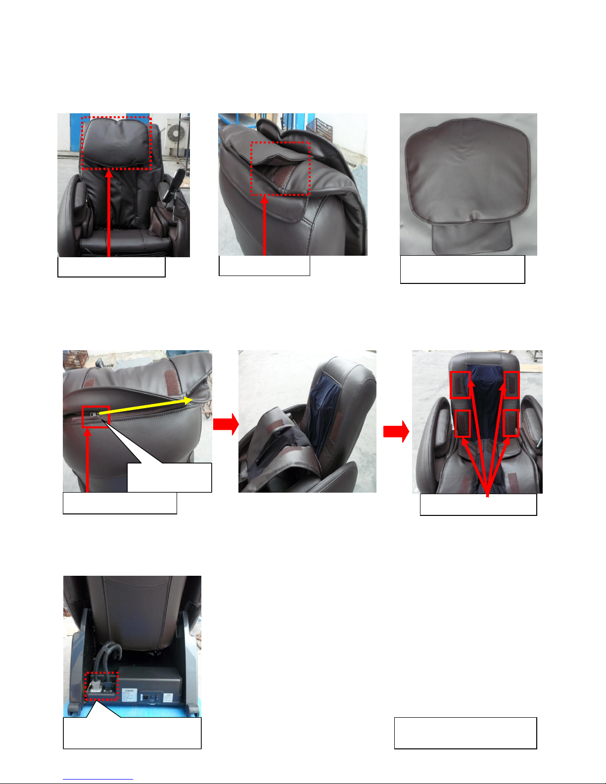
5-1: Guidance of Disassemble the Backrest Assy
A: Locate the pillow at the top, front of the chair. It is attached to the backrest pad via Velcro.
Detach it. ( As pictures below show)
B: Locate the zipper head of the backrest pad at the top, back of the chair. Unzip it to the end.
Then detach the backrest pad forwards from the backrest Velcro. ( As pictures below show)
C: Locate the backrest wire connecters at the bottom of the backrest. Then disconnect them.
(As pictures below show)
Locate the pillow
Locate Velcro
The pillow has been
detached
Unzip to the
end
Locate the zipper
4 Backrest Velcro
Locate the backrest
wire connecters
Backrest wires has
been disconnected
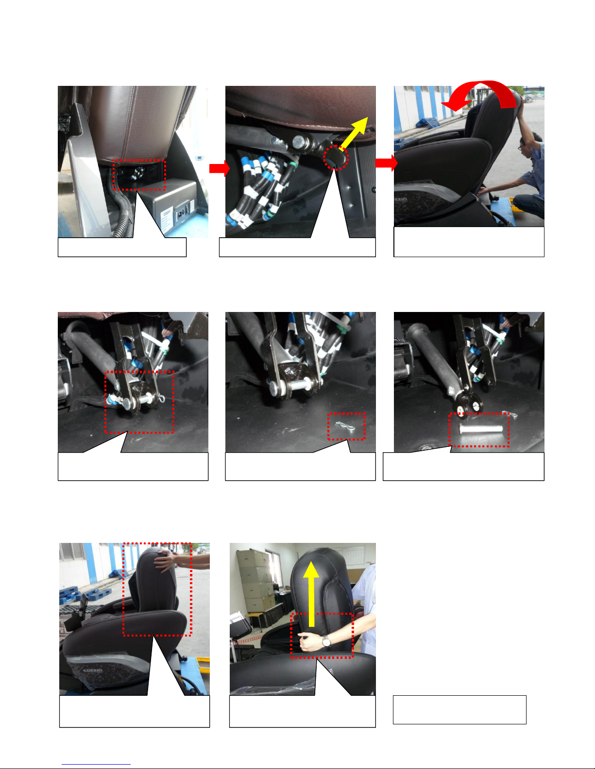
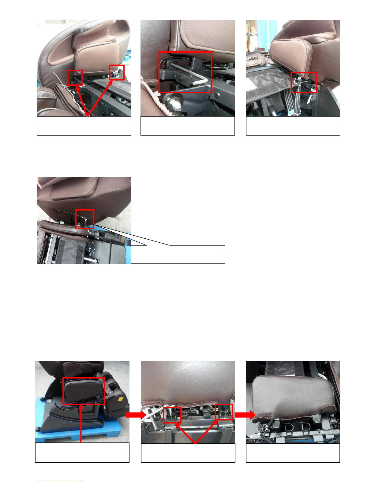
C: Locate the level lock at bottom of the backrest. Pull the level lock upwards to release from
the catch. Fold the backrest forward. ( As pictures below show)
D: Rest the backrest onto the seat pad Assy. Locate the cotter pin and the link at bottom of the
backrest. Remove the cotter pin first, then the link. ( As the pictures below show)
E: Adjust the Backrest Assy vertically and slowly lift the Backrest Assy upwards to detach. ( As
pictures below show )
Locate the level lock
Pull the level lock upwards
Push the backrest Assy
forwards
Locate the cotter pin &
link
The cotter pin has been
removed
The link has been removed
Adjust the backrest Assy
vertically
Hold the backrest at
here, then pull it up
The backrest has been
detached
5-2: Guidance of Disassemble the Backrest pad Assy
A: Disassemble the backrest assy. ( Refer to 5-1: Guidance of Disassemble the Backrest
Assy )
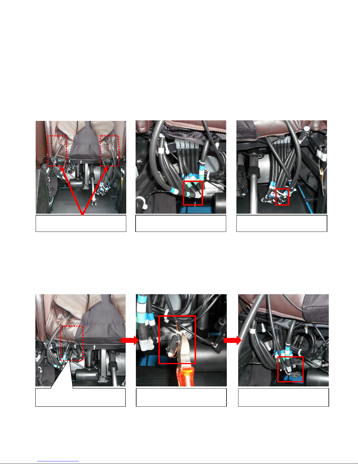
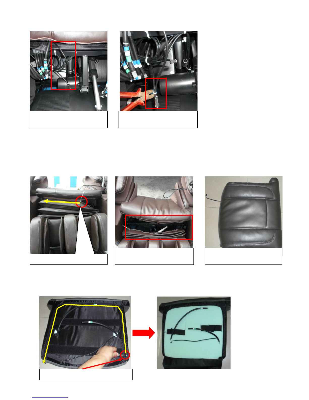
B: Locate the air hoses of backrest pad on the back of the backrest pad. Tracking along the air
hoses we can find the air hose connecters. Disconnect these two connecters. ( As pictures
below show)
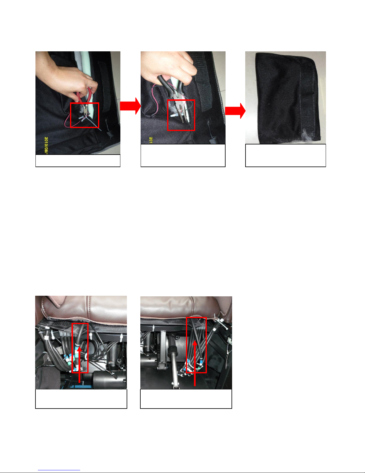
C: Locate the heater wire of the backrest pad. Tracking along the wire we can find the wire
connecter. Then use diagonal cutter get ride of the cable tie which secure the heater wire
connecter. ( As pictures below show )
D: Locate the zipper head of the zipper which between backrest pad assy and seat pad assy.
Thread a cable tie or something through the zipper head to unlock it. Unzip it to the end.
Locate the air hoses of
backrest pad
Locate one of the air
hose connecter.
Locate the other air hose
connecter
Locate the heater pad of
backrest wire.
Get ride of the cable tie
The wire connecter has
been disconnected
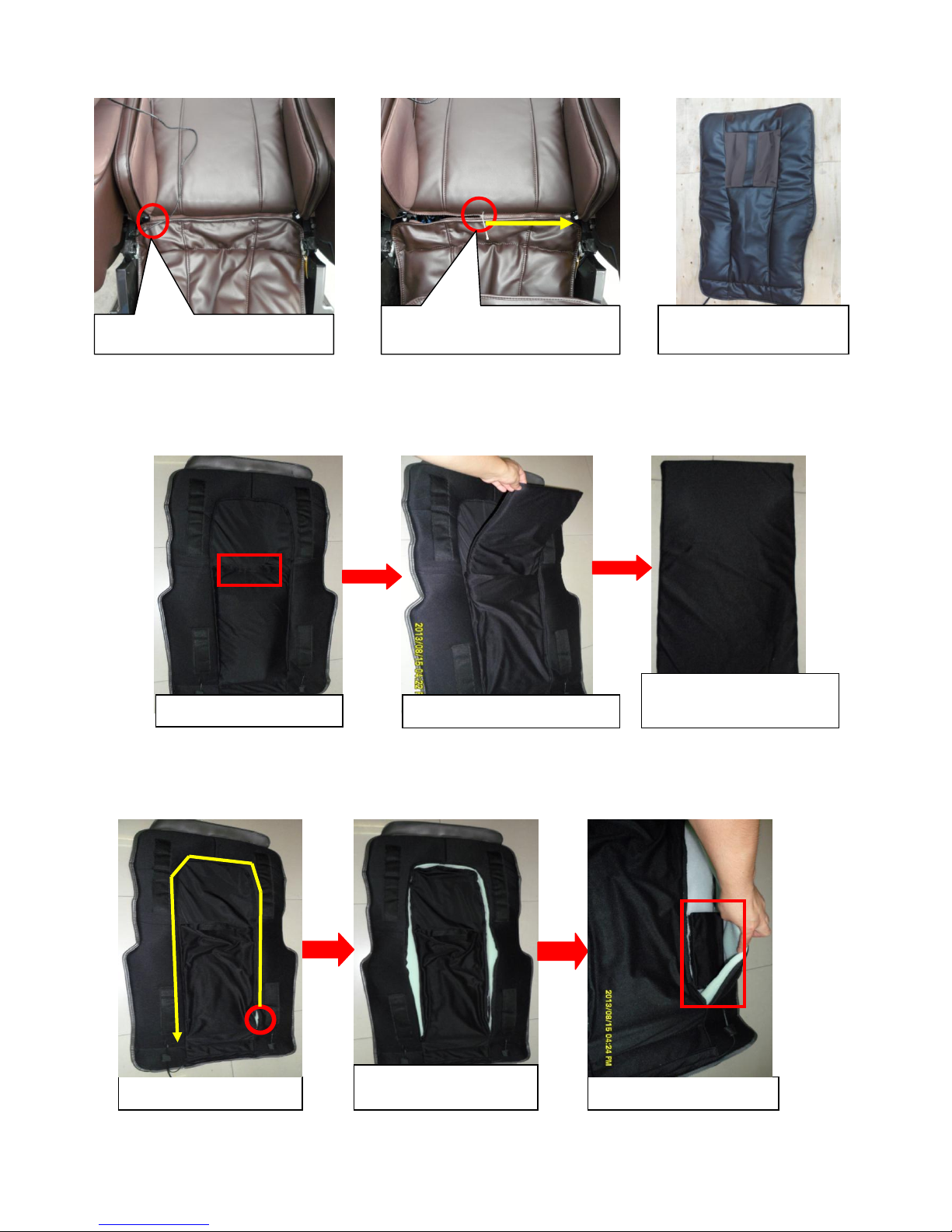
Then we can detach the backrest pad assy. ( As pictures below show )
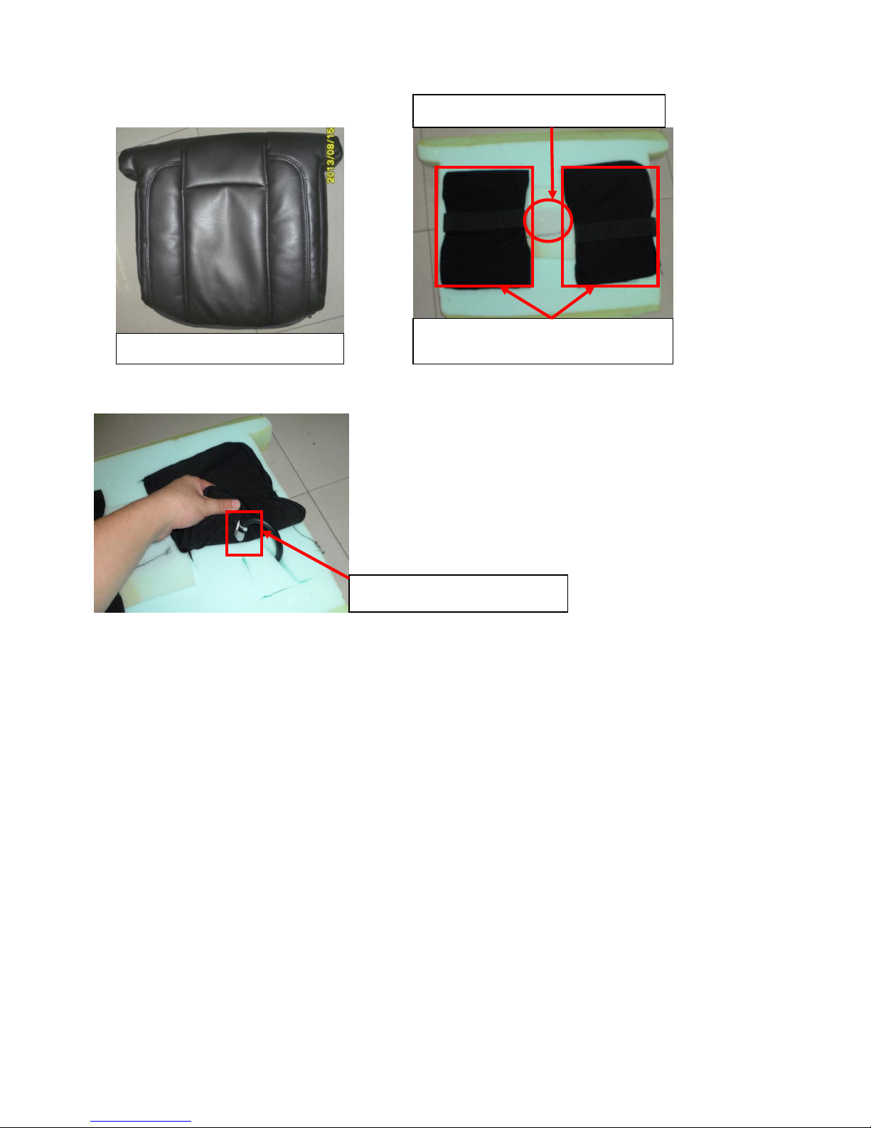
E: Separate the Velcro on the back of backrest pad. We can find a sponge pad inside. We can
take it out. ( As pictures below show )
F: Unzip the zipper which is on the rear side of backrest pad. We can find the heaters. ( As
pictures below show )
G: Use diagonal cutter get ride of the cable tie which secure the heater wire. Then use long
Locate the zipper head
Unzip the zipper to the
end
The backrest pad
has been detached
Locate the Velcro
Detach the sponge pad
The sponge pad has
been taken off
Unzip the zipper
Zipper has been
unzipped
Locate the heater
nose pliers get ride of the close end wire connecters. Then we can detach the heater. ( As
pictures below show )
5-3: Guidance of Disassemble the Seat pad Assy
A: Disassemble the backrest assy. ( Refer to 5-1:Guidance of disassemble the backrest assy. )
B: Disassemble the backrest pad assy. ( Refer to 5-2:Guidance of disassemble the backrest pad
assy.)
C: Locate the air hoses below the seat pad. Tracking along the air hose and we can find the air
hose connecters. Then disconnect them. ( As pictures below show )
D: Locate the vibration motor wire below the seat pad assy. Tracking along the air hose and we
can find the wire connecter. Use a diagonal cutter get ride of the cable tie which secure the
Cut the cable tie
Get ride of the close
end wire connecters
The heater has been
detached
Locate air hoses of seat
pad on the left
Locate air hoses of seat
pad on the right
wire connecter. Then disconnect it. ( As pictures below show. )
E: Locate the zipper head of the zipper which between seat pad and footrest upholstery.
Thread a small cable tie through the zipper head to unlock the zipper. Then unzip it to the
end. And then we can detach the seat pad assy. ( As pictures below show )
E: Use diagonal cutter get ride of the cable tie which secure the zipper heads. Then unzip the
zipper to the end. ( As pictures below show )
Locate the vibration
motor wire
Use diagonal cutter get
ride of the cable tie
Locate the zipper head
The zipper has been
unzipped
Seat pad has been
detached
Locate the zipper head
F: Take the seat pad cover off. Then we can see air bags and vibration motor. ( As pictures
below show)
G: Disconnect the air hose and we can detach the air bag. ( As pictures below show )
5-4: Guidance of Disassemble the Side Board.
A: Disassemble the backrest assy first. ( Refer to 5-1: Guidance of disassemble the backrest
assy.)
B: Disassemble the backrest pad assy. ( Refer to 5-2: Guidance of disassemble the backrest
pad assy.)
C: Disassemble the seat pad assy. ( Refer to 5-3: Guidance of disassemble the seat pad assy.)
D: Locate the two hexagon screw bolts. USE Allen Key slacken and remove these two screws
bolts. ( As pictures below show. )
Seat pad cover
Locate air bags
Locate the vibration motor
Locate air hose connecter
E: Locate the air hose connecter of the side board. Disconnect it. Then we can detach the side
board. ( As pictures below show. )
5-5: Guidance of Disassemble the Thigh Massage unit.
A: Disassemble the side board. (Refer to 5-4: Guidance of disassemble the side board.)
B: Locate the two hexagon screw bolts which secure the thigh massage unit. Use Allen Key to
slacken and remove these two screw bolts. ( As pictures below show. )
Locate the two hexagon
screw bolts
Remove the screw bolts
Remove the screw bolts
Locate the air hose
connecter.
Locate the thigh massage
assy
Locate the two hexagon
screw bolts.
The screw bolts have
been removed.

C: Disconnect the air hose then detach the thigh massage assy. ( As pictures below show )
D: Separate the Velcro then remove the cover of thigh massage assy. (As pictures below show )
E: Use screw driver slacken and remove the screws which secure the air bag. Then disconnect
the air hose. And then the air bag can be taken off. ( As pictures below show )
The thigh massage has
been taken off
Velcro has been
Separated
Cover of thigh massage
unit has been taken off
Use wrench to hold on
the screw nut, meanwhile
use screw driver slacken
and remove the screw
Disconnect the air hose
The air bag has been
taken off.
Locate air hose
connecters
Other manuals for CZ-388
3
Table of contents
Other Cozzia Massager manuals

Cozzia
Cozzia CZ-357 User manual

Cozzia
Cozzia EC-360D User manual

Cozzia
Cozzia CZ-710 Manual

Cozzia
Cozzia CZ-330 User manual

Cozzia
Cozzia CZ-710/Qi SE User manual

Cozzia
Cozzia ZEN CZ-641 User manual

Cozzia
Cozzia EC-362B User manual

Cozzia
Cozzia CG-5000 Manual

Cozzia
Cozzia HMC-200 Owner's manual

Cozzia
Cozzia CZ-710 Manual


