Cozzia BK-750 Manual

Maintenance Service Manual
Model:BK-750
BY COZZIA SERVICE DEPARTMENT

Catalog
1. Tools List.......................................................................................................................................2
2.1. Guidance of disassemble the Backrest Assy.................................................................................3
2.2. Guidance of disassemble the Footrest assembly..........................................................................4
2.3 Guidance of Disassemble the footrest PCB....................................................................................6
2.4 Guidance of disassemble the Rear cover of Backrest.................................................................... 7
2.5 Guidance of Disassemble the Rear cover of Headrest...................................................................7
2.6 Guidance of Disassemble the Bluetooth PCB.................................................................................8
2.7 Guidance of Disassemble the Side board.......................................................................................9
2.8 Guidance of Disassemble the Remote control..............................................................................11
2.9 Guidance of Disassemble the Remote control bracket/Wireless charge......................................11
2.10 Guidance of Disassemble the side board controller PCB............................................................13
2.11 Guidance of Disassemble the shoulder massage assembly/Seat side massage assembly..........14
2.12 Guidance of Disassemble the Main PCB/Power PCB/WIFI PCB/Bluetooth Audio PCB...............15
2.13 Guidance of Disassemble the massage mechanism...................................................................16
2.14 Guidance of Disassemble the Back stringing..............................................................................18
2.15 Guidance of Disassemble the Footrest actuator.........................................................................19
2.16 Guidance of Disassemble the zero gravity actuator....................................................................20

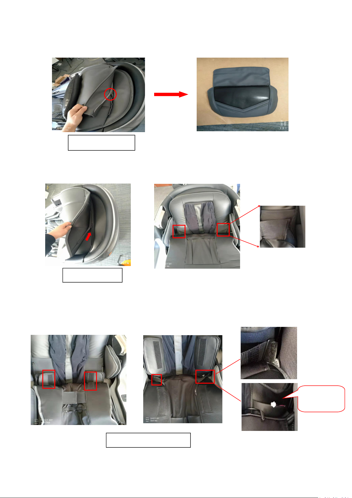
2.1 Guidance of Disassemble the Backrest Assy
A: Locate the zipper between the pillow and backrest pad,unzip the zipper to the end.Then the pillow can
be take off.
B: Locate the zipper between the backrest pad and backrest.Unzip the zipper to the end.Then detach the
backrest pad forwards from the backrest .Unzip the zipper that on the both side of backrest.
C: Continue to detach down the backrest pad,we should also detach the four Velcros and disconnect the
heater wire connector at backrest left. ( As pictures below show)
Locate the zipper
Locate the zipper
Detach the four Velcros
disconnect
the connector

D: Locate the zipper between seat pad and footrest cushion .unzip the zipper to the end.Then locate the
zipper in front of seat pad,unzip the zipper to the end.
E: Locate the zipper on both sides of seat pad ,unzip the zipper to the end.Then the backrest Assy can be
take off.
2.2 Guidance of Disassemble the Footrest assembly
A:Locate the zipper between seat pad and footrest cushion .unzip the zipper to the end
Locate the zipper
The backrest pad can be take away
Locate the zipper
Locate the zipper
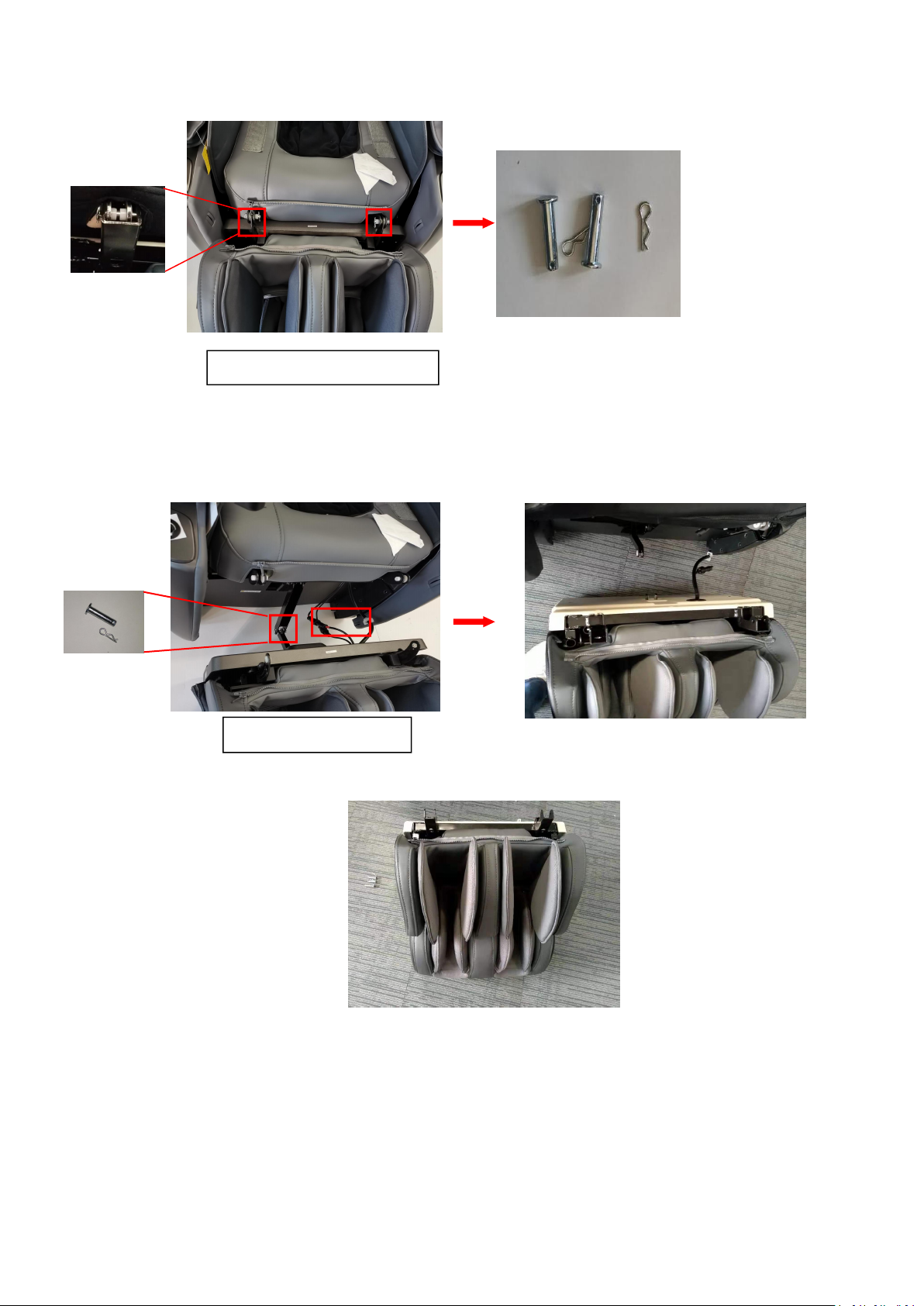
B:Locate the two cotter pins that fix on the seat and footrest ,then take off them.
C: Move backward the footrest we can find the another cotter pin that fixing the footrest.Remove the
cotter pin and disconnect the air hose connector wire with harness connector.Then the footrest can be
take away.
Locate the two cotter pins
Locate the cotter pin
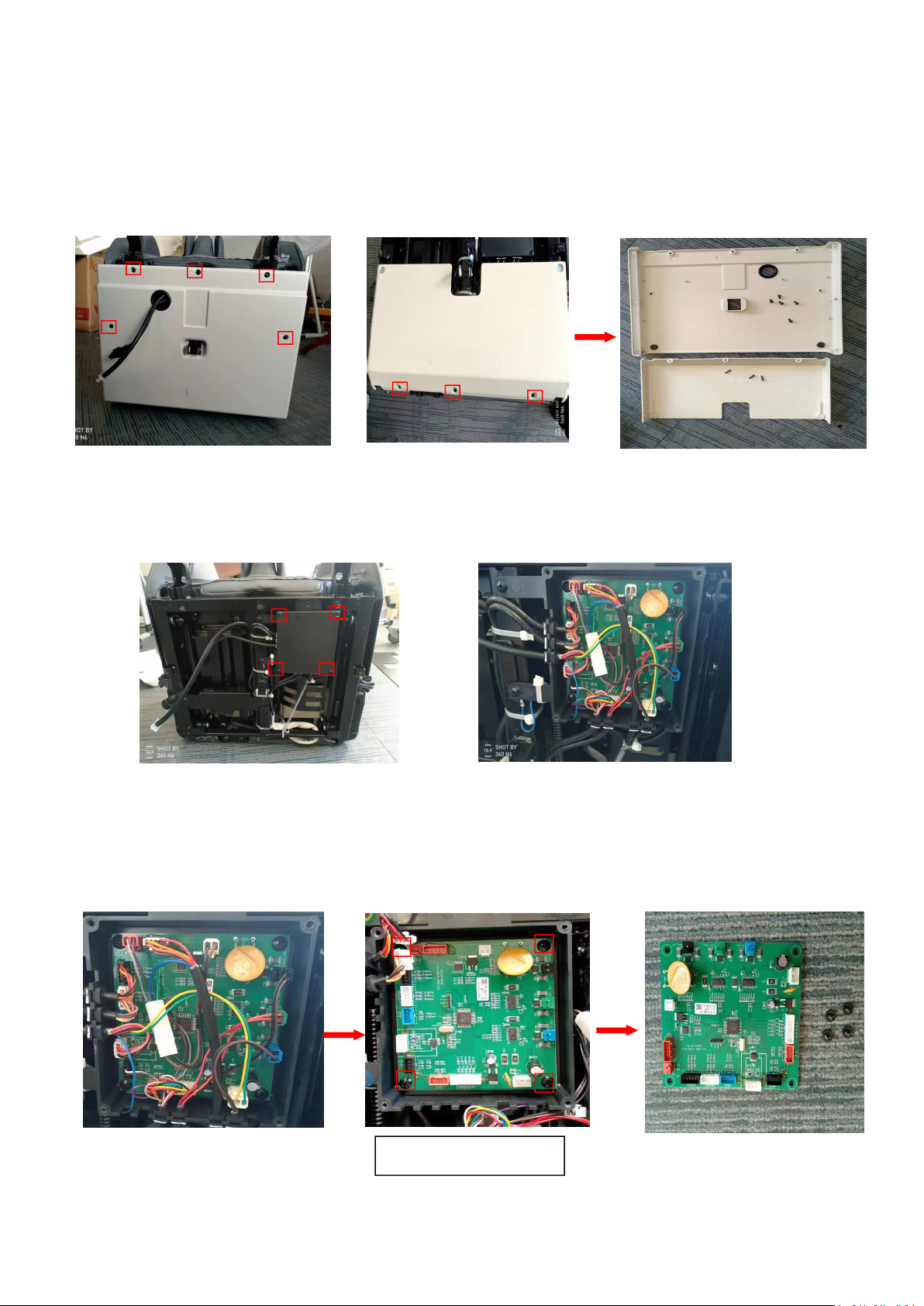
2.3 Guidance of Disassemble the footrest PCB
A:Take off the Footrest assembly(Refer to Guidance of Disassemble the Footrest assembly)
B:Locate the eight screws that fixing the rear cover of the footrest assembly and use screwdriver slacken
and remove these screws.
C:Locate the four screws that fixing the PCB box cover and remove them,we can find the footrest PCB.
D: Disconnect the wire connector on the footrest PCB and take off the four screws which fixing the Footrest
PCB.Then the Footrest PCB can be take off.
Locate the four screws
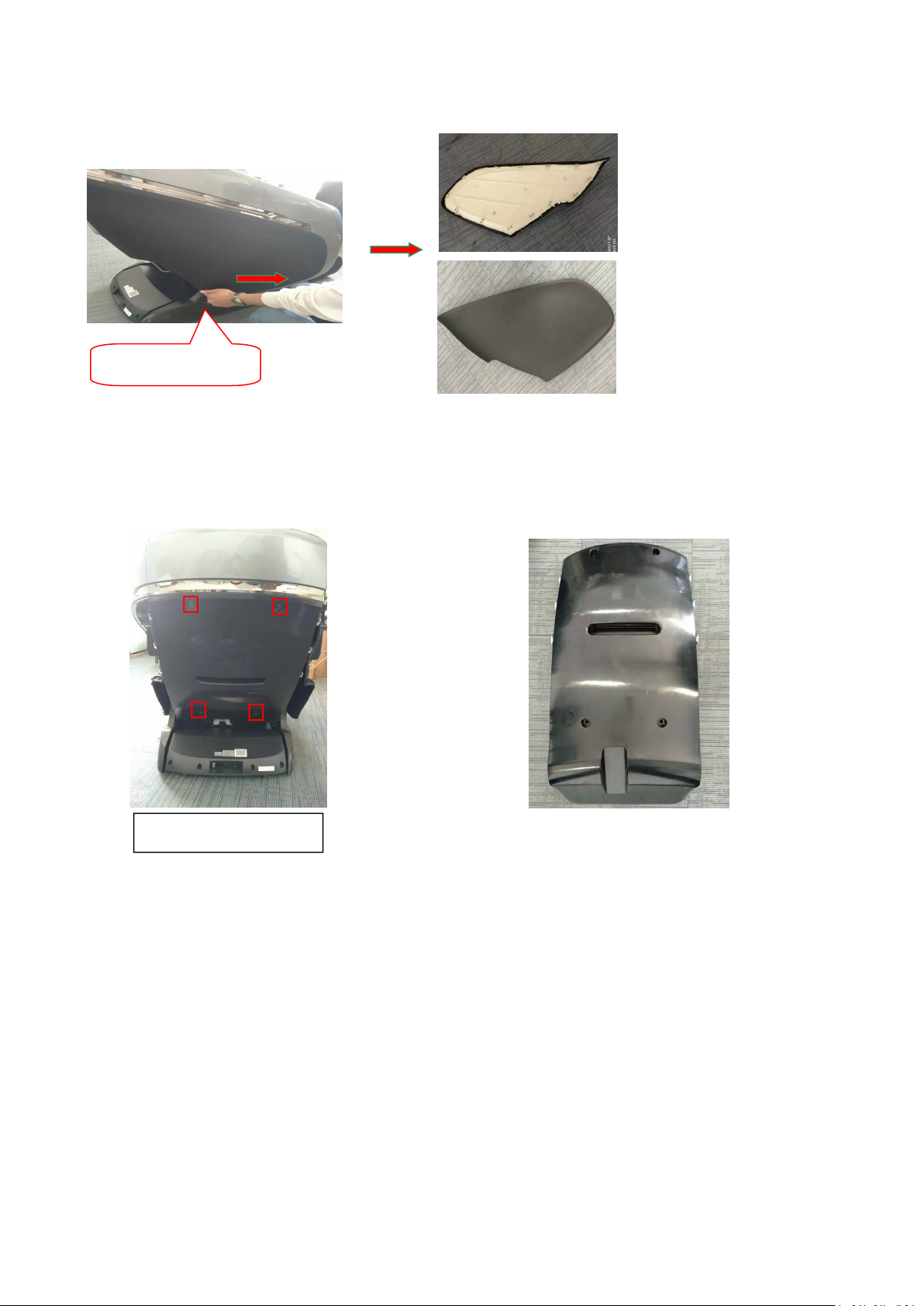
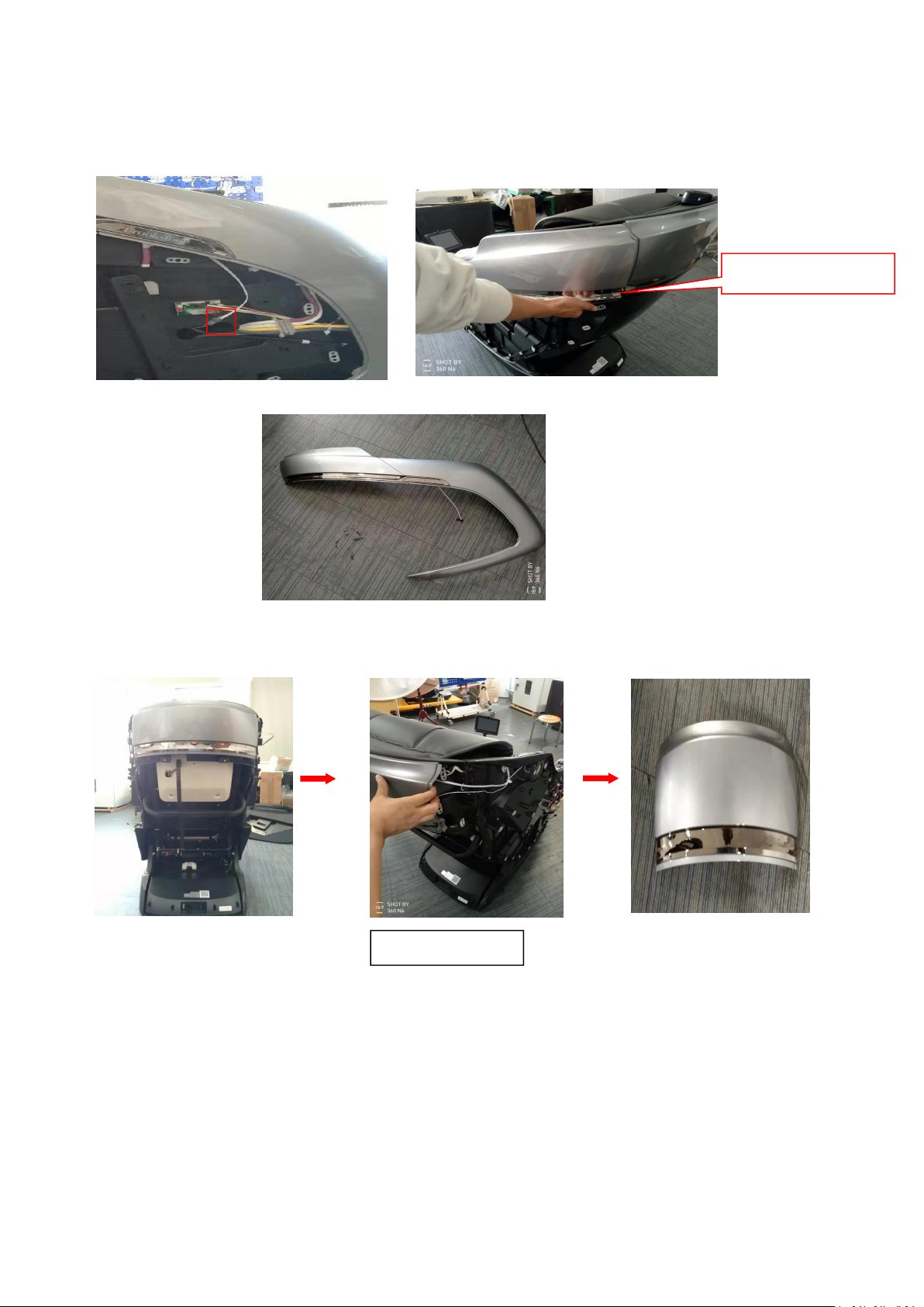
2.4 Guidance of Disassemble the Rear cover of Backrest
A:Take off the outer cover of side board on both sides that you should just pull it of,no screws.
( As pictures below show)
B:Locate the four screws on the rear cover backrest.Use screwdriver remove these screws.Then we can
detach the rear cover.
2.5 Guidance of Disassemble the Rear cover of Headrest
A:Detach the Side board outer cover and rear cover of backrest(Refer to Guidance of Disassemble the Rear
cover of Backrest)
Locate the four screws
Pull here like this
B:Disconnect the Light belt connector .Then detach the Side board decorative parts the same as detach the
Side board outer cover,just pull it of and the decorative parts can be take off. (Attention:Be careful to do not
damage the decorative parts)
C:After remove decorative parts on both sides,we can take off the headrest cover .
2.6 Guidance of Disassemble the Bluetooth PCB
A:Take off the rear cover of Headrest(Refer to Guidance of disassemble the rear cover of Headrest )
Pull of here more easy
No screw,pull it of

B:Locate the Bluetooth PCB inside of backrest .Then disconnect the wire connector on the Bluetooth PCB
and take off the four screws which fixing the Bluetooth PCB.Then the Bluetooth PCB can be take off.
2.7 Guidance of Disassemble the Side board
A: Take off the rear cover of backrest(refer to Guidance of Disassemble the Rear cover of Backrest)
Take off the rear cover of Headrest(refer to Guidance of Disassemble the Rear cover of Headrest)
B:Locate the three screws that fixing speaker and remove them.Disconnect the speaker connector from the
Bluetooth PCB meanwhile disconnect the shoulder lamp belt connector,Then we can take off the speaker
disconnect the connector

C:Locate the four hexagon that fixing side board on the frame and remove them.Then locate and remove
the other six screws that secure the side panel on the rear headrest cover
D:Disconnect the air hose connector and unplug the wire connector.
E: Lift the side board upwards then we can take off the side board.
Locate the Six screws
Locate the four hexagon
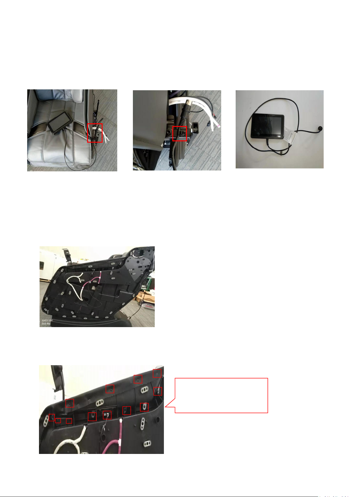
2.8 Guidance of Disassemble the Remote control
A:Take off the left side board.(Refer to Guidance of Disassemble the Side board)
B:Track the remote control wire find the wire clip on the frame.Use screw driver remove the screw which
secure the wire clip.Slacken and remove the wire connector cap and take off the remote control.
2.9 Guidance of Disassemble the Remote control bracket/Wireless charge
A:Take off the left side board outer cover and decorative parts(Refer to Guidance of Disassemble the Rear
cover of Headrest )
B:Locate the screws that fixing the armrest and the connector that connect the Wireless charge.Then use
screwdriver slacken and remove these screws and disconnect the Wireless charge connector.
Attention:
there are 11 screws and 1
connector

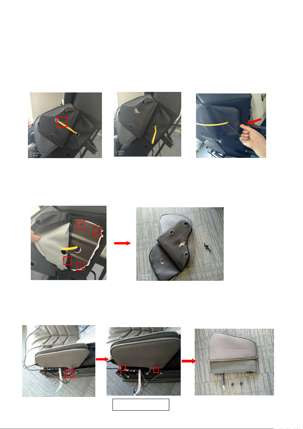
C:Pry outward with minus screwdriver and lift upward,then we can take off the armrest. ( As pictures below
show) (Attention:Be careful ,the armrest easy to deform)
D:Remove the screw and we can take off the remote control bracket.
E:Locate the four screws and remove them,we can take off the Wireless charge .
Pry the armrest gentle
Slacken and remove it
Locate the four screws

2.10 Guidance of Disassemble the side board controller PCB
A:Take off the right side board outer cover and decorative parts(Refer to Guidance of Disassemble the Rear
cover of Headrest )
B:Locate the screws that fixing the right armrest and remove it.Then take off the right armrest and
disconnect the connector on the side controller PCB.(Refer to Guidance of Disassemble the Remote control
bracket/Wireless charge)( As pictures below show)
C:Locate the five screws and remove them,we can take off the side controller PCB.
Locate the 9 screws
Disconnect the connector
Locate the 5 screws
2.11 Guidance of Disassemble the shoulder massage assembly/Seat side
massage assembly
A:Take off the side board(Refer to Guidance of Disassemble the side board )
B:Disconnect the air hose connector of shoulder massage.Then unzip the zipper of shoulder massage cover
to end.
C: Locate the four screws that fixing the shoulder massage and remove them.Then the shoulder massage
assembly can be take off.
D:Disconnect the air hose connector of seat side massage.Then locate the two screws that fixing seat side
massage on the frame,remove it.Then the seat side massage assembly can be take off.
Locate the 2 screws

Locate the 4 screws
Locate the 4 screws
2.12 Guidance of Disassemble the Main PCB/Power PCB/WIFI PCB/Bluetooth Audio PCB
A:Locate the six screws that fixing the PCB box cover.Use screw driver slacken and remove the screws then
take off the main PCB box cover.
B:Locate the main PCB on the PCB tray.Disconnect all the wire connectors that connected to it.Then slacken
and remove the screws that fixing the main PCB, then the main PCB can be take off.
C:Locate the power PCB on the PCB tray.Disconnect all the wire connectors that connected to it.Then
remove the screws that fixing the main PCB,then the power PCB can be take off.
There are two screws
on the inside

Locate the screws and connector
D:Locate the WIFI PCB on the PCB tray.Disconnect all the wire connectors that connected to it.Then remove
the screws that fixing the WIFI PCB,then the WIFI PCB can be take off.
E:Locate the Bluetooth Audio PCB on the PCB tray.Disconnect all the wire connectors that connected to
it.Then remove the screws that fixing the Bluetooth Audio PCB,then the Bluetooth Audio PCB can be take
off.
2.13 Guidance of Disassemble the massage mechanism
A:Take off the rear cover of backrest(Guidance of Disassemble the Rear cover of Backrest)
Take off the Rear cover of Headrest (Guidance of Disassemble the Rear cover of Headrest)
B:Disconnect all terminals connected to the Bluetooth PCB.Locate the screws that fixing the Headrest inner
cover and remove it.Then the Headrest inner cover can be take off.
Locate the screws and connector

C:Locate the screws that fixing rear cover of massage mechanism and Back stringing.Use screwdriver
slacken and remove these screws then we can take off the rear cover of massage mechanism.
D:Use the diagonal cutter get ride of the cable ties which fasten the Back stringing.Then disconnect the
connector which the Back stringing on the PCB.
E:Locate and remove the massage mechanism exit iron baffle on the frame.
Take off the Back stringing
Locate the exit iron baffle

F:Locate the red rolling motor wire connector and disconnect it.Use DC12~24V power supply connect to
connector to drive the mechanism out of the rack .Then the massage mechanism can be detach.
2.14 Guidance of Disassemble the Back stringing
A:Disconnect the connector which the Back stringing on the massage mechanism PCB.(Refer to Guidance
of Disassemble the massage mechanism)
B:Locate and remove the screws that fixing Back stringing on the frame.Then Use the diagonal cutter get
ride of the cable ties which fasten the Back stringing on the frame.
C:Locate the wire connector then disconnect them.The back stringing can be take off

2.15 Guidance of Disassemble the Footrest actuator
A:Take off the footrest first(Refer to Guidance of Disassemble the footrest assembly ).
Take off the backrest Rear cover(Refer to Guidance of Disassemble the Rear cover of backrest)
B:Locate the four screws on the front baffle .Take off the screws that fixing the front baffle and take off the
front baffle
C:Use the diagonal cutter get ride of the cable ties which fasten actuator wires to the frame.Then tack the
footrest actuator wire harness to locate the wire connector.Then disconnect them.
D:At front and rear of footrest actuator there are bolt which fixing the footrest actuator to the
frame.Remove the cotter pin and take off the bolts ,then we can detach the footrest actuator.
Locate the screws
Bolt at rear of thefootrest actuator.
Bolt at front of thefootrest actuator.
Table of contents
Other Cozzia Massager manuals


Cozzia
Cozzia CZ-640 User manual

Cozzia
Cozzia Renew Instruction Manual

Cozzia
Cozzia CZ-710 Manual

Cozzia
Cozzia 16028 User manual

Cozzia
Cozzia CZ-710/Qi SE User manual

Cozzia
Cozzia CZ-710 Manual

Cozzia
Cozzia CZ-628 User manual

Cozzia
Cozzia CG-5000 Manual

Cozzia
Cozzia MC-520 User manual

Cozzia
Cozzia Qi SE User manual


