CPC 485 User manual

4S5ALARMPANEL
P.N. 8114850
DOCUMENT No. 0254850
August, 1989
Data, drawings and other material con-
tained herein are proprietary to Computer
Process Controls, Inc. and may not be
reproduced without the prior approval of
Computer Process Controls.
Computer Process Controk, Inc.
1275 l{ennestone Circle, Suite 100
Marieua" GA 30066 (404) 425-2724 c?c
A]ARM 485
SET UP AND OPERATION
1. Modes of Operation
There are two modes of operation for the unit. They are:
Mode Display lndication
1. No Unacknowledged Alarms Date/Time & .'NO AIARMS" displayed.
You may press an arrow key to view any
"old" alarms in memory.
2. Unacknowledged alarms Date/Time &'Al-ARMS"displayed.
Press an arrow key to view current
alarms. Press "RESET' ONCE TO
SILENCE, TWICE TO COMPLETELY
RESET ALAHM. lf alarm reoccurs, the
annunciator will sound again.
When the unit is first powered ON, the display will indicate the time, date, and "NO
A1-ARMS". lf the unit'has been powered rip Sireviously, the internal memory may contain
alarm messages. lf this is the c'ase, the stored. alarms may be reviewed by press.ing .
either of the irrow buttons. lf no alarms have been stored, the display will show blank
alarms when scrolling with the arrow buttons.
- 2. Displaying Alarms
The following will describe the use of the arrow buttons to scrollthrough alarms stored
in memory.
The alarm messages may be thought of as a list on a sheet of paper. The display is
simply a window moving'up or down the page viewing the first two or second two lines
of any one alarm. Eaclialarm is made up olfour lines (two screens).
The down arrow will take you to the second two lines of an alarm, or to the next alarm,
depending on where you -are at when you press it. The first two lines of an alarm give
informatioh about timir and date and unit number, the second two lines give a
description of the alarm.
The up arrow willtake you to previous alarms or from the second two lines of a given
alarm to the first two lines of that alarm.
Pressing both arrow keys simultaneously will set the display back to viewing .'A[-ARMS"
or "NO ALARMS" and ttie scrolling wind6w back to Alarm #1. The unit will store a
maximum of 20 alarms.
3. Receiving Alarms
When the unit receives an alarm message, the LCD will display the wgrd "A[ARMS', the
alarm L.E.D. will illuminate, and the audi-ble alarm will sound (if the unit is set to do this).
At this point, the RESET button can be pressed once to silence the audible alarm. This
will allow thd user to view the current alarm(s) without the annoyance of the audible
alarm. lf the RESET button is pressed a sebond time, the current alarms in the 485
Alarm will be acknowledged ahd a "Fleset Alarms" message will be broadcast to all
attached devices that reSpond to the 485 Alarm. Before resetting alarms,.the pending
problems should be solvdld or the alarm will reoccur and equipment problems or
product loss could occur.
lf the 485 Alarm loses communications, it willturn on both the LED and audible alarms
ind display "Network Down". This may be.acknowledged Py pre^ssing the RESET
Outton.'This error suggests a wiring oi switch setting problem. Communications will be
initiated by another d6Vice in tess than 5 minutes or i-mmediately upon powering up the
485 alarm.
4.0 Clearing Alarms
Using either the power switch behind the lower access.panel, or the power cord,
remo-ve power frbm the 485 Alarm. Hold down all four keys and power u.p tpud! All
alarms viitt Ue cleared. lf the unit goes into the "Clock Sett' mode, press the RESET
button until "No Alarms" appears on the display.
5.0 485 Clock Setting
The following procedure sets the 485 Alarm Panel internal clock.
1. lnsure that the display shows "No Alarms".
2. Press and hold down the RESET button.
3. Press and release the TEMPS button.
4. Use the arrow buttons to incremenVdecrement the month.
5. Quickly press and release the RESET button. Notice the indicator on the second line
points to the "days" position.
6. Rbpeat steps 4 and S'for the day, hour, minute and AM/PM indicator.
7. When the date and time are as desired, a final press of the RESET button will return
the user to the "No Alarms" or "Alarms" display.
2
6. Hardware Setup
The network and mode switches are located under the bottom access panel.
6.1 Netnvork Switches set the device lD and baud rate.
Switches 1 thru 5 define the board device number (1-16).
Most applications are set for lD=1.
POSITION
!D 12345
0 00000 l=ON
1 10000 2=OFF
2 01000
3 1 1000
Switches 6 and 7 set the baud rate (normally 4800 baud). Set the baud rate using the
table below.
POSITION
BAUD AJ.
\-' 12oo o o
24W 10 l=ON
4800 01 2=OFF
9600 1 1
6.2 Jumpers JU3, JU4, and JUS set terminating resistance for the RS 485
communications bus.
DEVICES AT THE ENDS OF THE 485 BUS WIHING REQUIRE TERMINATING
RESISTORS FOR PROPER OPERATION OF THE ENTIRE NETWORK. IF THE
NETWORK ENDS AT THE 485 ALARM, MOVE THE TEBMINATING JUMPERS
FUHTHEST AWAY FROM THE 48s TEHMINAL BLOCK (TOP POSITION).
These jumpers are located on the 485A board right next to the BS-485 communication
terminal blbck. The jumper positions depend onhow the Expansion Communication
Bus is wired.
6.3 Printer Port Setup
Mode switch 1 should be ON to enable the printer. OFF disables the printer.
6.4 Audible Alarm.
Mode switch 2 enables/disables the audible alarm. Off ENABLES the audible alarm.
3

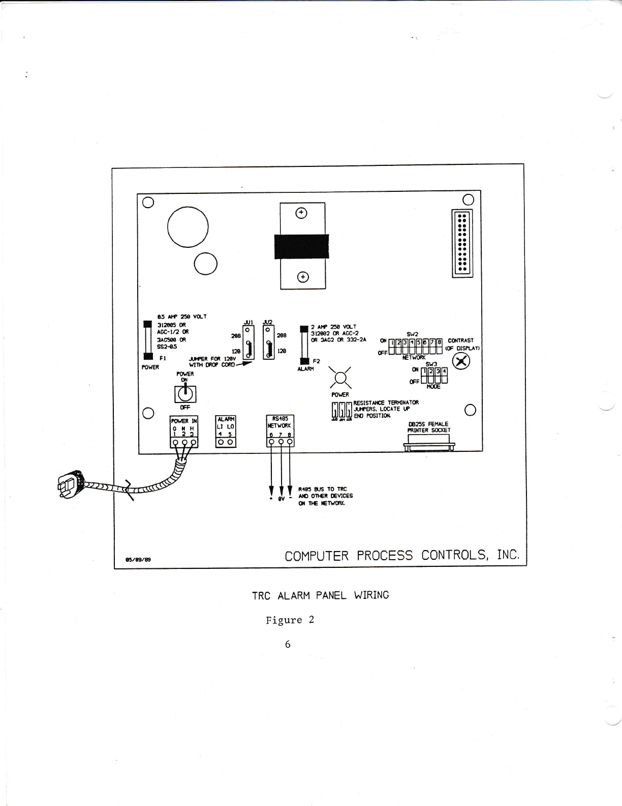
7.0 lnstallation
Mount the 485 Alarm using the six mounting holes on the outside of the enclosure.
Figur6 i. snows mounting-dimensions. Figure 2. shows.the Ylng. P9w-er.pay.be via
inElupplied drop cord aid a standard duplex outlet at 120VAC, or wired direclly to a
convehi'ent poweir supply. Connect terminals 6, 7, and I to the RS 485 network on any
1602's that you are monitoring.
8.0 Specifications
Microprocessor
Communications
Power Requirement
Features
Dimensions
Mounting Dimensions
Weight
8751 Microcontroller
RS-485 lnterface operating at 1200,
2400,4800, or 9600 Baud.
PA Y AC |208VAC Selectable
Parallel printer port, Realtime clock,
Audible and LED alarm, Alarm Reset
8.75"X8.625"X4.75*
See Figure 1.
Approx. 4 LB.
4
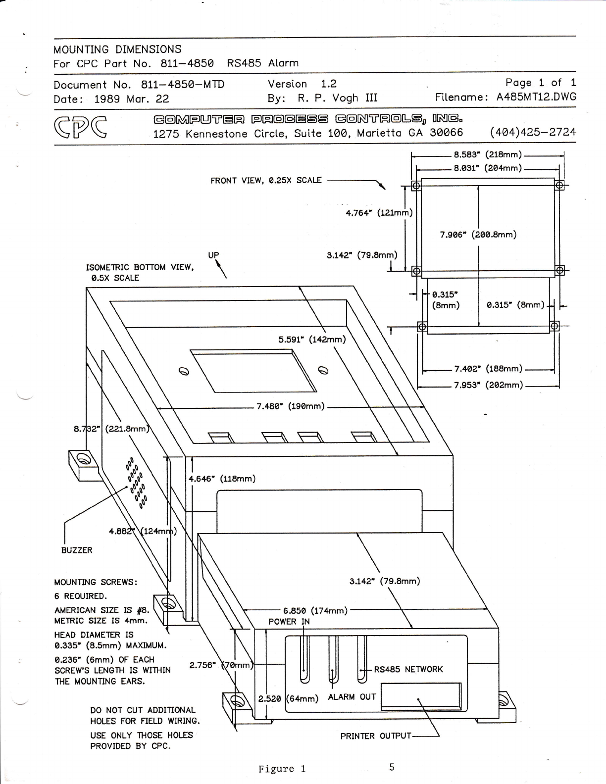
MOUNTING DIMENSIONS
For CPC Port No. 811-4850 RS485 Atorm
Document No. 8LL-485O-MTD
Dote: 1989 Mor. 22 Version L.2
By: R. P. Vogh III Poge 1 of L
Fttenome : A485MT12.DWG
GPG G@RNF[JTEH
L275 Kennestone FH@GESS E@nSTH@LSD
Circte, Suite L@O, Mor\etto GA IngG"
30066 (4@4)4zs-2724
(218mm)
ISOMETRIC BOTTOM VIEW,
O.sX SCALE
FRONT VIEW, 0.25X SCALE __----\
4.764' (121m;
3.L42'(79.8mm
P
\
BUZZER
MOUNTING SCREWS:
6 REOUIRED.
AMERICAN SIZE IS #8.
METRIC SIZE IS 4mm.
HEAD DIAMETER IS
0.33s' (a.smm) MAXIMUM.
0.236' (6mm) oF EACH
SCREW'S LENGTH IS WIfiIN
lHE MOUNTING EARS.
DO NOT CUT ADDITIONAL
HOLES FOR NELD WIRING.
USE ONLY 'IHOSE HOLES
PROVIDED BY CPC.
8.583' (218mm)
8.$L- (2o4rn ) _l I
)
)
7.9a6', (2l00.8mm)
0.315'
(8mm) 0.315' (8mm)
7.4o2' (raamm)
7.953' (202mm)
5.591' (142mm)
7.48a- (rs0mm)
(22l.Amm
4.646', (uamm)
6.85@ (174mm)
Figure 1
PRINTER OUTPUT
\i
R,r83 EJS rO lRC
I st, I rrc orrER oEvIcEs
(,l n+ Er\rcnr.
COMPUTER PROCESS CONTROLS, INC.
e5 Alf 250 vo-l
I rras u r'
1'1 tr# *J:l
U :i"' r,GR Fm ,#U
For{ER lrllH InC W@=-
IOrER
0I
I1T\I
lL./ I
TRC ALARM PANEL WiRING
Figure 2
6
Y

Other manuals for 485
1
This manual suits for next models
1
Table of contents
Other CPC Security System manuals

Popular Security System manuals by other brands


EDM
EDM Solution 6+6 Wireless-AE installation manual

Highway Safety Group
Highway Safety Group EA401 user manual

Siren
Siren LED GSM operating manual

Detection Systems
Detection Systems 7090i Installation and programming manual

Se-Kure Controls
Se-Kure Controls MicroMini SK-4841 instructions

Siemens
Siemens FDM273 manual