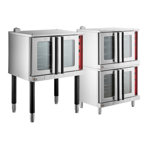
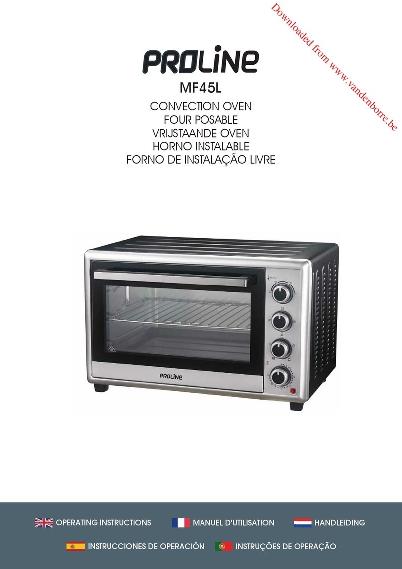
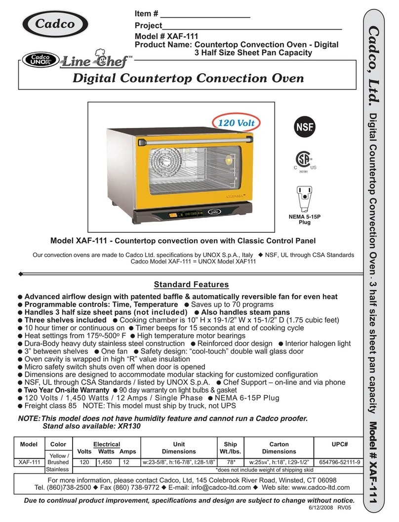
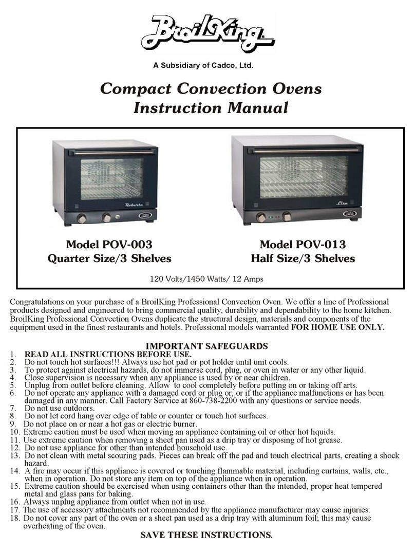
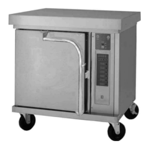
CPG 351FGC100 User manual

NOTICE
This manual is for a certied service technician and should not be used by those who are not
properly trained. This manual cannot cover all possible conditions that may occur and is not
intended to be all encompassing. You should read this manual in its entirety and the specic
repair you wish to do prior to starting the repair. This will allow you to determine if you have
the correct tools, instruments, and skills to perform the procedure.
¾"
Gas Powered
Convection Ovens
03/2022
Service Manual
351FGC100(L/N) | 351FGC200(L/N)K
351FGC100DD(L/N) | 351FGC200DD(L/N)K
Cooking Performance Group . www.cookingperformancegroup.com

. www.cookingperformancegroup.com2
Service Manual
351FGC100(L/N) | 351FGC200(L/N)K
351FGC100DD(L/N) | 351FGC200DD(L/N)K
Contents
Troubleshooting ..........................................3
Part Testing
Main Power Switch ..................................4
Cook/Cool Switch (Fan Mode).........................4
Fan Speed Switch ...................................5
Light Switch ........................................5
Timer ..............................................6
Buzzer .............................................6
Thermostat .........................................6
Transformer.........................................7
Ignition Module......................................7
Door Switch ........................................8
Heat on Indicator Light ...............................8
Surface Ignitor ......................................9
Flame Sensor .......................................9
Gas Solenoid Valve ................................ 10
Temperature Sensor ............................... 10
Panel Safety Switch ............................... 10
Part Replacement
Fan Motor ........................................ 11
Gas Burner Components ........................... 11
Internal Gas Regulator ............................. 12
Gas Conversion ................................... 12
Regulator Press Adjustment ........................ 12
Door Latch Removal ............................... 13
Door Latch Adjustment ............................ 13
Wiring Diagram ........................................ 14
Parts Diagram .......................................15-18

www.cookingperformancegroup.com 3
Service Manual
351FGC100(L/N) | 351FGC200(L/N)K
351FGC100DD(L/N) | 351FGC200DD(L/N)K
Troubleshooting
Problem Possible Solution
Burner will not turn on
Ensure gas supply is turn on.
Ensure gas supply is at the correct pressure.
Ensure unit is plugged in and has correct voltage.
Ensure unit power switch is on.
Ensure doors are closed and cook switch is engaged.
Check thermostat is set above current inside oven temperature.
Check ignition module is not locked out with RED LED light blinking.
Check surface igniter.
Check internal gas valve.
Burner will not turn off
Check thermostat is turned "OFF".
Check temperature sensor/probe.
Check internal gas valve.
Burner ames are
small or weak
Check gas supply pressure is correct.
Check manifold pressure with manometer.
Check burner air openings, adjust if needed.
Check orice opening for each burner.
Check ventilation is setup correctly.
Burner ame will not
light or maintain ame
Check gas pressure at manifold.
Check burner air openings, adjust if needed.
Check surface igniter.
Check orice openings.
Check ame sensor.
Check ignition module.
Burners are producing
a black soot
Ensure correct gas is supplied, reference nameplate.
Ensure correct ventilation is set up.
Check burner air openings.
Check orice openings.
Blower fan will not turn on
Ensure unit is plugged in and power switch is 'ON'.
If in 'cook' mode, ensure doors are closed.
Check correct voltage is going through power switch.
Check voltage is getting to fan.
Check fan speed switch.
Check both door switches.
Oven is not reaching
temperature
Ensure thermostat is set to correct temperature.
Ensure fan is running.
Ensure burners are staying on.
Check thermostat probe.

. www.cookingperformancegroup.com4
Service Manual
351FGC100(L/N) | 351FGC200(L/N)K
351FGC100DD(L/N) | 351FGC200DD(L/N)K
Part Testing
Main Power Switch
Cook/Cool Switch (Fan Mode)
1. Check for continuity, disconnect wires from rear terminals on switch, check between middle
and lower terminals when 'ON'. If none found, replace switch. If found move to next check
below.
2. With unit plugged in, check for 0.5 amps at 120 volts from #3 wire to #5 wire at back of
power switch (middle to lower terminal). (Fig. 1)
3. Check for any discoloration or deformations of electrical connections. If any are found,
replace connections.
1. Check for continuity. Disconnect wires from rear terminals on switch, check between middle
and top terminal when switch is on 'COOK' and then between middle and lower terminal
when switch is on 'COOL'. If continuity is not found in both switch positions, replace switch.
If found in both positions, see below for more testing.
2. With unit turned 'ON', check for 0.5 amps at 120 volts from
middle to top terminal when switch is on 'COOK'. (Fig. 3)
3. With unit turned 'ON'; check for 0.5 amps at 120 volts from
middle to lower terminal when switch is on 'COOL' (Fig. 3)
4. Check for any discoloration or deformations of electrical
connections. If any are found,
replace connections.
CAUTION: Components can be HOT
!
Fig. 1
Fig. 3
Fig. 2

www.cookingperformancegroup.com 5
Service Manual
351FGC100(L/N) | 351FGC200(L/N)K
351FGC100DD(L/N) | 351FGC200DD(L/N)K
Fan Speed Switch
Light Switch
1. Disconnect wires from rear of switch. Check continuity between middle and top terminals
and switch in 'HI' position. Then check continuity between middle and lower terminals and
switch is in 'LOW' position. If continuity is not found in both switch positions, replace switch.
If found in both positions, see below for more testing.
Fan running check:
- Fan speed = HI, check for voltage at the neutral (rear of the unit) and at the rear of switch,
bottom terminal. Voltage = 120 volts at 0.5 amps (Fig. 4)
- Fan Speed = Low, check for voltage at the neutral (rear of the unit) and at the rear of the
switch, top terminal. Voltage = 120 volts at 0.5 amps (Fig. 4)
2. Middle terminal on switch should always have power when unit is on.
3. Check for any discoloration or deformations of electrical connections. If any are found,
replace connections.
1. Disconnect wires from rear of switch. Check continuity between middle and lower terminal
when switch is 'ON', position. If continuity is not found in 'ON' position, replace switch. If
found, see below for more testing.
2. Reconnect wires and with light switch turned 'ON' and unit plugged in and 'ON'. Check for
voltage between neutral and lower terminal.
3. Check for any discoloration or deformations of electrical connections. If any are found,
replace connections.
Fig. 4
Fig. 6
Fig. 5
Fig. 7

. www.cookingperformancegroup.com6
Service Manual
351FGC100(L/N) | 351FGC200(L/N)K
351FGC100DD(L/N) | 351FGC200DD(L/N)K
Timer
Buzzer
Thermostat
1. Disconnect wires from rear of timer.
Turn timer knob to 0 minutes, check for
continuity across terminals on rear of
switch. If none is found, replace timer.
(Fig. 9)
2. Turn knob to between 1 and 60 minutes,
check that no continuity is found. Turn
knob to 'OFF', check that no continuity
is found. If continuity is found, replace
timer. (Fig. 9)
3. Check for any discoloration or
deformations of electrical connections.
If any are found, replace connections.
1. Disconnect wires from buzzer. Check
across terminals for approx. 2.4
kilo-ohms +/-10%. If outside of range,
replace buzzer. (Fig. 10)
2. Check for any discoloration or
deformations of electrical connections.
If any are found, replace connections.
1. Visually check board for any burners
or discoloration or corrosion. If found,
replace thermostat.
2. Check for 120 volts from COM terminal
(Fig. 12A) to input terminal (Fig. 12B).
3. Check for 24 volts from COM terminal
(Fig. 12A) to output terminal (Fig. 12C).
4. Check for any discoloration or
deformations of electrical connections. If
any are found, replace connections
Fig. 8
Fig. 10
Fig. 9
Fig. 11
Fig. 12
C
BA

www.cookingperformancegroup.com 7
Service Manual
351FGC100(L/N) | 351FGC200(L/N)K
351FGC100DD(L/N) | 351FGC200DD(L/N)K
Transformer
Ignition Module
1. Check for 120 volts at terminals (Fig. 13A).
2. Check for 24 volts at terminals (Fig. 13B). If voltage is
not correct, replace.
3. 24 volts goes to thermostat, 'HEAT ON' lamp and gas
solenoid valve.
4. Check for any discoloration or deformations of electrical
connections. If any are found, replace connections.
Check that module has power, check for 120 volts from L1 connection to GND connection and
also from L1 connection to a Neutral wire on the back of unit (Fig. 15 & 16).
Red Light Denitions:
- Solid red, no blinks: control fail, replace ignition module
- 2 blinks: ame on, but no call for heat, check thermostat
- 3 blinks: no ame, ignition locked out, check ignition sequence parts (surface igniter, gas
solenoid valve, ame detector)
S1 connection - 120 VAC surface igniter
L1 connection - 120 VAC input power (live)
W connection - Fan motor then thermostat
V1 connection - Gas solenoid valve
GND connection - Ground
S2 connection - Flame sensor
Fig. 14 Fig. 15 Fig. 16
Fig. 13
B
A

. www.cookingperformancegroup.com8
Service Manual
351FGC100(L/N) | 351FGC200(L/N)K
351FGC100DD(L/N) | 351FGC200DD(L/N)K
Door Switch
Heat on Indicator Light
1. Disconnect wires from rear of switch. Check continuity between terminals when switch lever
is in 'CLOSED', position. If continuity is not found in 'CLOSED' position, replace switch. If
found, see below for more testing.
2. With wires disconnected, check for no continuity between terminals when switch lever is
'OPEN'. If continuity is found, replace switch. If not found, see below.
3. With unit 'ON' and unit plugged in, check for 120 volts from each terminal to neutral when
switch is 'CLOSED', (Fig. 18) image shows terminal closest should only have 120 volts when
door is closed.
4. Check for any discoloration or deformations of electrical connections. If any are found,
replace connections.
1. With unit 'ON', plugged in and unit calling for heat, check for 24 volts between terminals.
Replace if no voltage is found or light does not light (Fig. 19).
2. Check for any discoloration or deformations of electrical connections. If any are found,
replace connections.
Fig. 17
Fig. 19
Fig. 18

www.cookingperformancegroup.com 9
Service Manual
351FGC100(L/N) | 351FGC200(L/N)K
351FGC100DD(L/N) | 351FGC200DD(L/N)K
Surface Igniter
Flame Sensor
1. Visually check that surface igniter 'glows' when thermostat rst calls for heat. Check with
unit 'ON' and thermostat calling for heat (Fig. 20 & 21).
2. Check for 120 volts from S2 connection on ignition module to Neutral wire on back of unit
(Fig. 22).
3. Check for 0.8 - 1.5 amps from S2 connection on ignition module to Neutral wire on back on
unit (Fig. 22).
4. Disconnect wire terminals, check resistance through igniter, approx. 23 Ohms at 70°F.
1. Visually check that ame sensor 'glows' when burner ames are 'ON'. Check with unit 'ON',
thermostat calling for heat and burner ames 'ON' (Fig. 25).
2. Check for 5 VDC on ignition module 'FC' terminals. If less than 2 VDC, replace ame sensor
(Fig. 24).
Fig. 20
Fig. 23
Fig. 21
Fig. 25
Fig. 22
Fig. 24

. www.cookingperformancegroup.com10
Service Manual
351FGC100(L/N) | 351FGC200(L/N)K
351FGC100DD(L/N) | 351FGC200DD(L/N)K
Gas Solenoid Valve
Temperature Sensor
Panel Safety Switch
1. Ensure gas is being supplied to unit. Check
incoming pressure using manometer on inlet
side of valve.
2. Check if solenoid valve is getting 24 VAC. If
no voltage, check ignition module. If voltage
is found, and still no gas is coming through,
replace gas valve (Fig. 26).
3. Check for any discoloration or deformations of
electrical connections. If any are found,
replace connections.
1. Disconnect wiring from thermostat. Check
resistance of sensor across wire terminals,
1.1 kilo-ohms +/- 10 % at 70° F. Replace
if outside of range (valve will change with
temperature) (Fig. 27).
2. Check for any discoloration or deformations of
electrical connections. If any are found,
replace connections.
1. Disconnect wires from rear of switch. Check
continuity between terminals when switch is in
'CLOSED' position. If continuity is not found in
'CLOSED' position, replace switch. If found, see
below for more testing (Fig. 28).
2. With wires disconnected, check for no continuity
between terminals when switch is in 'OPEN'. If
continuity is found, replace switch. If not found
see below.
3. With unit 'ON' and unit plugged in, check for 120 volts from each terminal to neutral when
switch is 'CLOSED'. Replace if not found on both terminals.
4. Check for any discoloration or deformations of electrical connections. If any are found,
replace connections.
Fig. 26
Fig. 27
Fig. 28

www.cookingperformancegroup.com 11
Service Manual
351FGC100(L/N) | 351FGC200(L/N)K
351FGC100DD(L/N) | 351FGC200DD(L/N)K
Fan Motor
Gas Burner Components
1. Turn unit off, disconnect gas and electrical
connections.
2. Remove right side panel to disconnect motor
wires from inside plug (Fig. 29).
3. Remove wiring from rear of unit (Fig. 30 & 31).
4. Open front doors. Remove racking and top rear
rack brackets from inside of oven.
5. Remove inside rear cover with a 10mm socket
or wrench, 2 bolts (Fig. 32 & 33).
6. Remove mounting bolts for fan motor with a
10mm socket or wrench (Fig. 34).
7. Pull fan assembly into inside of oven (Fig. 35).
8. Reassembly is reverse of removal.
1. Turn unit off. Disconnect gas and electrical
connections.
2. Remove front lower cover panel with a Phillips
screw driver.
3. Loosen and remove compression nut from gas
supply line to burner manifold (Fig. 36).
4. Remove 4 hex head bolts with an 8mm socket
from the burner manifold (Fig. 37).
5. Replace orices as needed or for gas
conversion, use a 14mm wrench.
6. Remove 4 hex bolts with an 8mm socket from
burner assembly to access the burners, surface
igniter and ame sensor (Fig. 38 & 39).
7. Remove surface igniter and/or ame sensor
with a Phillips screw driver as required for
replacement (Fig. 40).
8. Disconnect wiring from ignition module if
replacing surface igniter or ame sensor.
Fig. 29
Fig. 32
Fig. 34
Fig. 39
Fig. 36
Fig. 37
Fig. 38
Fig. 33
Fig. 35
Fig. 40
Fig. 30 Fig. 31
Part Replacement

. www.cookingperformancegroup.com12
Service Manual
351FGC100(L/N) | 351FGC200(L/N)K
351FGC100DD(L/N) | 351FGC200DD(L/N)K
ALL GAS CONNECTIONS MUST BE CHECKED FOR LEAKS
!
ALL GAS CONNECTIONS MUST BE CHECKED FOR LEAKS
!
Internal Gas Regulator
Gas Conversion
Regulator Pressure Adjustment
1. Turn unit off. Disconnect gas and electrical connections.
2. Remove hex bolts holding right side on with an 8mm
socket.
3. Loosen and remove compression nut and union joint from
either side of regulator to remove from unit (Fig. 41).
4. Remove ttings from both sides of old valve and install
on new valve with an appropriate thread sealant.
5. Install is reverse of removal. Ensure there are no gas
leaks.
1. Convert from one gas type to another by changing the burner orices. Reference 'Gas Burner
Components' on Page 11.
2. Replace regulator adjustment spring assembly. Reference 'Regulator Pressure Adjustment'
below.
3. Add new gas decals to Serial plate and internal regulator to reect change in gas supply type.
1. Manifold pressure can be adjusted. If needed and if
incoming pressure allows.
2. Remove right side panel hex bolts with an 8mm socket
and remove panel, then remove front lower cover.
3. Install manometer onto burner manifold behind lower
front panel to check pressure (reference serial plate for
required pressure), monitor if changes are needed
(Fig. 42).
4. Remove adjustment cover cap on inlet side of
regulator with a at screw driver (Fig. 43).
5. Turn adjustment screw under cap as follows:
Counter-Clockwise: Decrease pressure
Clockwise: Increase pressure
Fig. 41
Fig. 42
Fig. 43

www.cookingperformancegroup.com 13
Service Manual
351FGC100(L/N) | 351FGC200(L/N)K
351FGC100DD(L/N) | 351FGC200DD(L/N)K
Door Latch Removal
Door Latch Adjustment
1. Turn off power switch and gas supply to unit.
2. Disconnect unit from power supply.
3. Open front door(s) on unit to access latch.
4. Remove 2 Phillips head screws and pull latch from
top of door (Fig. 44).
5. Installation is reverse of removal.
1. Turn off power switch and gas supply to unit.
2. Disconnect unit from power supply.
3. Open front door(s) on unit to access latch.
4. Remove 2 Phillips head screws and pull latch from
top of door.
5. Push in on top portion of latch to remove tension
from lower locking nuts.
6. With an 8mm socket and/or wrench, turn the 2 nuts
to adjust the latch as needed.
7. Clockwise will lower the latch roller into the door.
Counterclockwise will raise the latch roller out of
the door.
8. Installation is reverse of removal.
Fig. 44
Fig. 45

. www.cookingperformancegroup.com14
Service Manual
351FGC100(L/N) | 351FGC200(L/N)K
351FGC100DD(L/N) | 351FGC200DD(L/N)K
Wiring Diagram

www.cookingperformancegroup.com 15
Service Manual
351FGC100(L/N) | 351FGC200(L/N)K
351FGC100DD(L/N) | 351FGC200DD(L/N)K
Parts Diagram
Item # Description Part #
2Blower Motor - 2 Speed 351010239
2A Blower Wheel 351010212
3Temperature Probe 351170022
4Oven Light 351130151
8Gas Safety Valve - NG 351220079
8A Gas Safety Valve - LP 351220098
9Panel Safety Switch 351080026
Item # Description Part #
15 Burner Assembly See Burner Assembly
16 Burner Orifice - LP 351302150211
16A Burner Orifice - NG 351302150212
17 Control Panel Assembly See Control Panel Assembly
19 Door Assembly - Right See Door Assembly
20 Door Assembly - Left See Door Assembly
22 Door Switch 351080079

. www.cookingperformancegroup.com16
Service Manual
351FGC100(L/N) | 351FGC200(L/N)K
351FGC100DD(L/N) | 351FGC200DD(L/N)K
Burner Assembly
Item # Description Part #
1Flame Sensor 351220004
2 Burner 35165002071
5Flame Spreading Plate 35165002068
7Surface Igniter 3511170039

www.cookingperformancegroup.com 17
Service Manual
351FGC100(L/N) | 351FGC200(L/N)K
351FGC100DD(L/N) | 351FGC200DD(L/N)K
Control Panel Assembly
Item # Description Part #
1 Buzzer 351100086
3Power Switch 351080141
4Ignition Module 351150304
5 Timer 351120028
7 Transformer 351100149
Item # Description Part #
8 Thermostat 351030169
9Heat Light 351130140
Fan Speed Switch 351080141
Light Switch 351080141
Cool/Cook Switch 351080141

. www.cookingperformancegroup.com18
Service Manual
351FGC100(L/N) | 351FGC200(L/N)K
351FGC100DD(L/N) | 351FGC200DD(L/N)K
Door Assembly
Item # Description Part #
1 Door Latch 35165002016
Door Assembly - Left 35165002014
Door Assembly - Right 35165002011
Other manuals for 351FGC100
1
This manual suits for next models
11
Table of contents
Other CPG Convection Oven manuals
