Cradlepoint COR IBR600 User manual

White Paper /COR IBR600 Vehicle Installation Guide
Cradlepoint Vehicle
Best Practices
Installation Guide
Using Cradlepoint COR IBR600
Router in 12 V and 24 V
Vehicles
WHAT YOU’LL GET:
+Overview of basic in-vehicle
electrical systems.
+The basics of power
management.
+Voltage regulation &
DC-DC converters.
+Filters, installation, fusing,
wiring, mechanical, and
thermal considerations.

White Paper /COR IBR600 Vehicle Installation Guide
©2017 Cradlepoint. All Rights Reserved. |+1.855.813.3385 |cradlepoint.com 2
OVERVIEW
The automotive environment can be particularly harsh for
electrical equipment such as routers and mobile devices. Power
in automotive systems is not stable and is often subject to
uctuations and noise.
Vehicle electrical systems are typically 12 V or 24 V, but the
actual voltage can vary widely depending on the condition of the
batteries and whether the engine is o, cranking, or running.
Just as important, many potentially damaging transient voltages
exist on vehicle power wiring. These transients, sometimes called
“spikes,” are caused by motors for electric windows, solenoids
for door locks, alternators, relays, light switches, loose electrical
connections, and corroded battery terminals. The inductance in
the vehicle’s wiring harnesses may exacerbate these transients.
Transients of hundreds of volts, both positive and negative, can
be generated with the potential to cause damage to any
electrical equipment.
Our COR IBR600 router can operate safely on 9–18 volts DC.
However, for reliable operation in a vehicle, it requires additional
ltering and conditioning in 12 V vehicles and
additional voltage regulation in 24 V systems. Most other
Cradlepoint routers are specied to operate safely from 11.4
to 12.6 volts and require regulation and ltering for all vehicle
installations.
This paper will provide background on the problems
and solutions as well as guidance for the installation
of Cradlepoint devices. We’ll recommend some
commercially available products to help minimize the
eects of the harsh automotive power environment.
FOR PROPER
AND SAFE
INSTALLATION,
THE ROUTER
MUST BE
CONNECTED TO A
FUSED CIRCUIT IN
THE VEHICLE.

BASIC SYSTEM (NO PROTECTION)
It is possible to quickly wire a basic 12 volt system such as the simple installation shown in
this diagram where power is provided to the router by connecting the 12 V input lead from
the router to a connection in the vehicle fuse block and the ground wire to chassis ground.
However, this method provides no protection against voltage variations or voltage transients.
Erratic operation or even damage to your Cradlepoint product is much more likely than if
the methods shown in the following pages are used to condition the power provided to your
Cradlepoint product or other mobile device.
©2017 Cradlepoint. All Rights Reserved. |+1.855.813.3385 |cradlepoint.com 3
White Paper /COR IBR600 Vehicle Installation Guide

White Paper /COR IBR600 Vehicle Installation Guide
©2017 Cradlepoint. All Rights Reserved. |+1.855.813.3385 |cradlepoint.com 4
Battery
Ignition Switch
M
+-
Power Manager
Fig 1. Battery Voltage During Engine Start
POWER MANAGEMENT
These devices monitor the state of the battery
and other lines such as the ignition switch to
determine if power should be applied to the
mobile device. Possible features provided by
these may include the following:
+ Provides power only when ignition
switch is turned on.
+ Monitors the battery voltage. If the
battery voltage is too low or too high,
power to the mobile device is not allowed.
+ Monitors whether the starter motor is
engaged. Does not apply power to the
mobile device while engaged.
+ May allow the device to remain powered
on for a specied time after the ignition is
switched o to prevent battery drain. This
time is typically user programmable.
The graph in Figure 1 shows how the voltage
available from the battery is reduced signicantly
when the starter motor is engaged. The voltage
may fall well below the recommended minimum
voltage required by the router causing “brown
out” conditions and possible malfunction.

VOLTAGE REGULATION
Most vehicles are designated as either 12 or
24 volt systems, yet even though the battery
is designated as 12 volts the actual voltage at
its terminals during normal vehicle operation is
typically about 13.6 V. However, depending on
its age, state of charge, and electrical load can
typically range between 10 and 16 volts. 24 volt
systems have similar characteristics and can range
between 17 and 32 volts during normal operation.
Depending on model, Cradlepoint routers can
accept an input voltage of 9–18 volts which
means some sort of voltage regulation and
conditioning is generally required.
DC TO DC CONVERTERS
Commercially available DC-DC converters take a
wide voltage range from the battery and provide
a regulated DC voltage output, typically about
13.6 volts. These converters should supply low
ripple voltage, typically less than 250 mV. Higher
quality converters may also provide features such
as reverse polarity protection, isolation, current
limiting, short circuit protection, and overvoltage
protection.
For a 24 volt system a standard regulator that
simply lowers the voltage to 12–14 volts is
acceptable. In a 12 volt system a regulator may
need to either boost the voltage or reduce it.
This dual mode regulator may be somewhat more
expensive but will protect against “brown
out” conditions caused by low input voltage.
It is important that the DC-DC converter can
provide enough power for all devices with some
extra safety margin (reserve power). Do not use
an underpowered converter.
©2017 Cradlepoint. All Rights Reserved. |+1.855.813.3385 |cradlepoint.com 5
White Paper /COR IBR600 Vehicle Installation Guide
Vehicle
Type
12 Volt
System
24 Volt
System
Input
Range to
DC-DC
Converter
10–16 VDC
20–50 VDC
Typical
Output
Voltage
13.6 VDC
13.6 VDC
Battery
12 V / 24 V
+-
10–16 V (12 V system)
17–32 V (24 V system) 13.6 V
DC-DC
Converter
(12 V or 24 V
Model)

White Paper /COR IBR600 Vehicle Installation Guide
©2017 Cradlepoint. All Rights Reserved. |+1.855.813.3385 |cradlepoint.com 6
FILTERS
Voltage transients on the router’s 12 V input power lines
may cause erratic behavior or damage. This “noise” can
range in frequency from a single spike to a few kilohertz
or hundreds of megahertz and is typically caused by
electromechanical components in the vehicle, or even by
additional electrical accessories installed in the vehicle.
Filters may help control these transients; however, good
installation techniques must be followed to ensure best
router performance and protection.
+IMPORTANT—Filters should be placed as close as
practical to the router input power. Keep power
lines to the device short. Failure to do so may
reduce the eectiveness of the lter.
+ Noise lters can be as simple as a capacitor (or
two) placed across the 12 V power line into the
device. Adding an inductor and second capacitor
to form a “pi” lter is more eective. Fig 2. Location of the filter is important. Keep lines to
mobile devices short.
Fig 3. Filter component types. Pi is preferred.
+-
Battery
Noise received Noise generated
Noise generated
M
+-
Battery
Input
Ground
Output
Keep short

+ Capacitors (caps) should be rated at least
150% of the expected voltage and a low
ESR is preferred. Over time, a higher
temperature rated cap will be less likely to
fail.
+ Caps have eective frequency ranges
depending on the material used in their
construction.
+ Aluminum electrolytic, or “metal can,” caps
are used for lower frequency noise and
voltage dips. These caps have positive and
negative terminals and must be connected
correctly or damage will occur. Capacitance
values ranging from tens to hundreds of
thousands of microfarads (uF) are available.
For example a 5000 uF 35 V 85 ºC aluminum
capacitor would be a good starting value.
+ Ceramic capacitors are used to control high
frequency noise. It is critical to keep these
as close a possible to the device input and
keep lead lengths short. Typical values are
0.001–0.47 uF, 50 VDC.
+ Inline inductors must be capable of
handling the full load current of the
device(s) attached to it.
+ Pi lters are typically sold as “noise lters”
by automotive audio stores. These must
also be able to handle full load current.
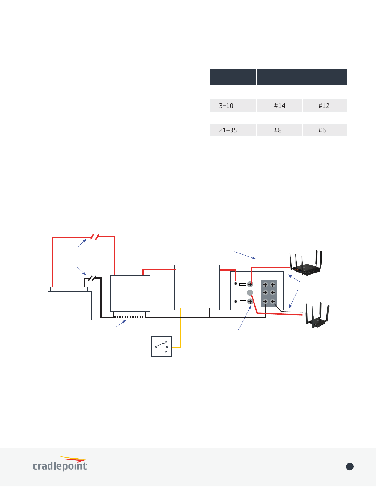
INSTALLATION, FUSING AND WIRING
Proper installation of the power conditioning
devices in relation to the mobile device you are
trying to protect is important.
+ It is best to locate all conditioning
devices such as DC-DC converters, power
management devices, distribution blocks,
and lters as close to the router equipment
as possible. That being said, some are more
critical than others.
+ Filters and distribution blocks should be
located as close to the mobile device(s) as
possible. Long power leads from the lter
to the mobile device can degrade or nullify
lter performance.
+ Use the proper wire size for the amount
of current being drawn. Long cable lengths
with undersized wire will result in voltage
losses over the length of the cable and
can possibly overheat (see table for
recommended wire size).
+ Use of a dedicated ground wire, rather
than attaching to chassis ground, may be
preferred.
+ Chassis ground can be susceptible to
corrosion eects and intermittent
connections.
©2017 Cradlepoint. All Rights Reserved. |+1.855.813.3385 |cradlepoint.com 7
White Paper /COR IBR600 Vehicle Installation Guide
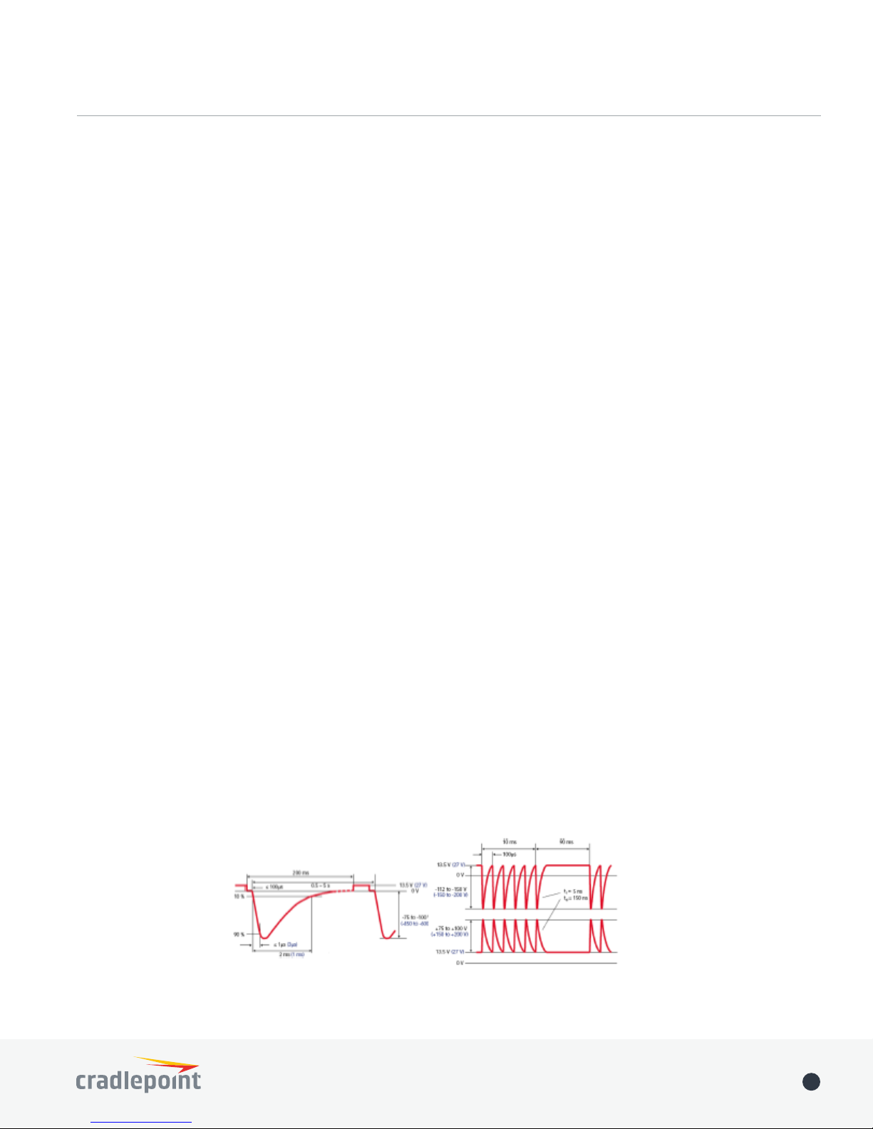
Fig 4. Standardized Examples of Automotive Transients (ISO-7637-2)

White Paper /COR IBR600 Vehicle Installation Guide
©2017 Cradlepoint. All Rights Reserved. |+1.855.813.3385 |cradlepoint.com 8
Fig 5. Possible Installation Configuration
Battery
12 V / 24 V
+-DC-DC
Converter
GND
IN OUT
13.6 VDC
No connection
if converter is
ISOLATED
Ignition
Switch
Fused Distribution
Block
Keep
cables
short
12 V IN 12 V OUT
IGNITION SW GROUND
Power Management
Long Cables Use
correct wire size
10–16 V (12 V system)
17–32 V (24 V system)
Filter
+ Isolation between devices is recommended.
Noise generated by one device can aect
another. If multiple devices are connected
at the same distribution point it may be
necessary to lter each device separately.
+ For proper and safe installation, the router
must be connected to a fused circuit in
the vehicle. For the COR IBR600 this fused
circuit requires a 1.5 A maximum time delay
(slow blow) high interrupting rating fuse. If
the supply connection is made directly to
the battery, the fuse should be installed in
the positive lead. For North America, a UL
Listed fuse is to be used.
AMPS Cable Length (AWG)
10’ 20’
3–10 #14 #12
11–20 #14 #10
21–35 #8 #6

MECHANICAL AND THERMAL
Electronics mounted in vehicles may subject to
high levels of mechanical and thermal stress. It is
important to understand that these parameters be
addressed to ensure a reliable installation.
+ Be sure the router is securely mounted
within the vehicle. For example with the
COR IBR600 family of routers includes a
mounting bracket. This bracket can hold the
router solidly in most installations. In high
shock environments it may be advisable to
add a supplemental cable tie to secure the
router in the bracket.
+ Vibration can cause early failure if not
reduced to an acceptable level. Using the
same COR IBR600 mounting bracket as
an example, special anti-vibration rubber
grommets such as the Keystone 773
(available from DigiKey) may be used. Insert
the grommets and then tighten the screw to
the point where the grommet just begins to
compress to provide vibration isolation.
+ Thermal ratings must be taken into
consideration for reliable operation. All
devices and components used in the
installation are subject to the same thermal
stresses. The COR IBR600 is rated for
ambient temperatures from -20 °C to 60 °C
(-4 °F to 140 °F). Various power conditioners
may have lower or higher ratings. Take care
that your installation is within the thermal
ratings of each device.
+ The ambient thermal environment may
be aected by many factors. Lack of
ventilation, being mounted in an auxiliary
box, or being mounted where the sun heats
it can all increase the relative ambient
temperature. Care must be taken to
understand these thermal aspects.
©2017 Cradlepoint. All Rights Reserved. |+1.855.813.3385 |cradlepoint.com 9
White Paper /COR IBR600 Vehicle Installation Guide
Fig 6. COR IBR600 Mounting Bracket
Other manuals for COR IBR600
8
Table of contents
Other Cradlepoint Automobile Accessories manuals