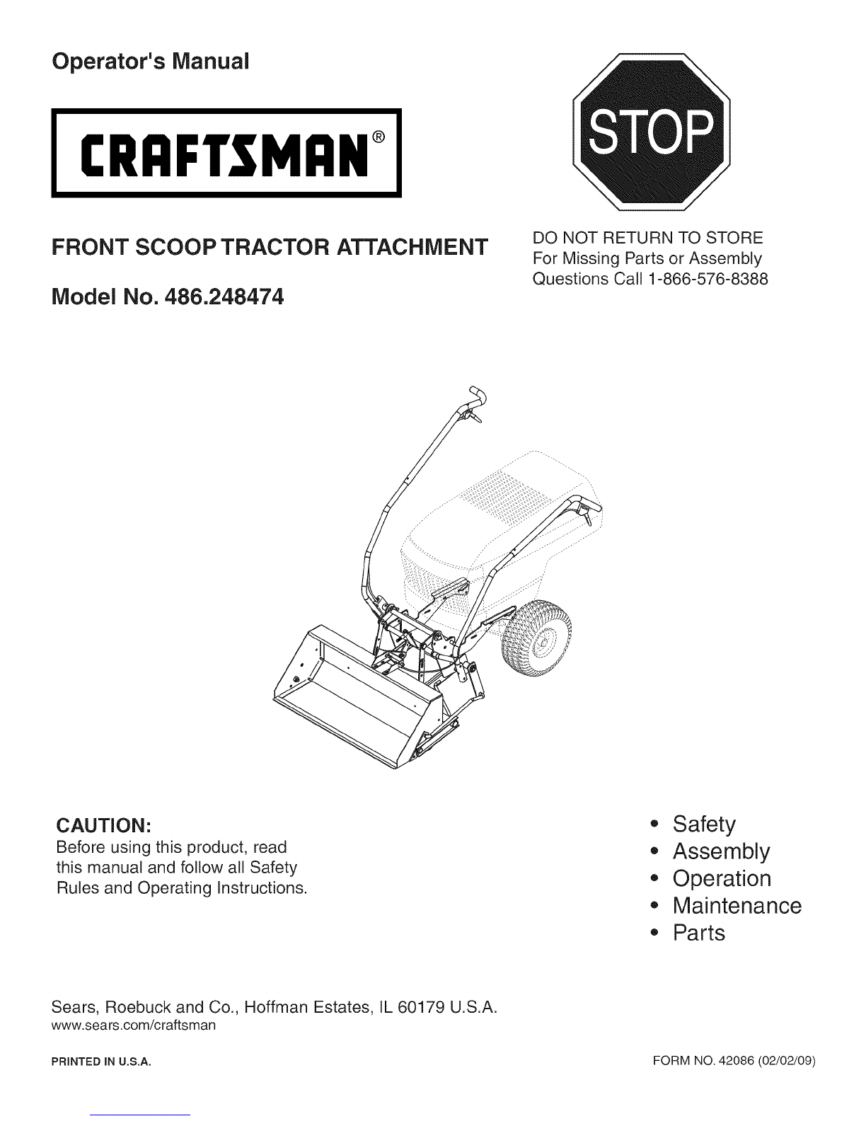
Craftsman 486.248474 User manual
Other Craftsman Lawn And Garden Equipment manuals

Craftsman
Craftsman 486.243291 User manual

Craftsman
Craftsman 486.24847 User manual

Craftsman
Craftsman 358.795660 User manual

Craftsman
Craftsman 486.24326 User manual

Craftsman
Craftsman 486.243001 User manual

Craftsman
Craftsman 486.24116 User manual

Craftsman
Craftsman 486.248463 User manual

Craftsman
Craftsman 320.74900 User manual

Craftsman
Craftsman 421264 User manual

Craftsman
Craftsman 358.799701 User manual

Craftsman
Craftsman ZTS 7500 User manual

Craftsman
Craftsman 486.244283 User manual

Craftsman
Craftsman 247.240193 User manual

Craftsman
Craftsman 247.24019 User manual

Craftsman
Craftsman 917.252492 User manual

Craftsman
Craftsman 486.244412 User manual

Craftsman
Craftsman 247.24019 User manual

Craftsman
Craftsman SNOW BLADE 486.24441 User manual

Craftsman
Craftsman 486.244121 User manual

Craftsman
Craftsman 0944.511590 User manual


Popular Lawn And Garden Equipment manuals by other brands

Vertex
Vertex 1/3 HP Maintenance instructions

GHE
GHE AeroFlo 80 manual

Millcreek
Millcreek 406 Operator's manual

Land Pride
Land Pride Post Hole Diggers HD25 Operator's manual

Yazoo/Kees
Yazoo/Kees Z9 Commercial Collection System Z9A Operator's & parts manual

Premier designs
Premier designs WindGarden 26829 Assembly instructions


AQUA FLOW
AQUA FLOW PNRAD instructions

Tru-Turf
Tru-Turf RB48-11A Golf Green Roller Original instruction manual

BIOGROD
BIOGROD 730710 user manual

Land Pride
Land Pride RCF2784 Operator's manual

Makita
Makita UM110D instruction manual

BOERBOEL
BOERBOEL Standard Floating Bar Gravity Latch installation instructions