LUBRICATION
U
All the bearings in this tool are lubricated with a suf-
ficient amount of high grade lubricant for the life of
the unit under normal operating conditions, there-
fore, no further lubrication is required.
operating
CHUCK-Your Router chuck is a precision collet type.
IMPORTANT-DO NOT TIGHTEN THE COLLET UN-
LESS A FULL SIZE 1;4 INCH SHANK BIT IS IN THE
COLLET AS THIS MAY CAUSE THE COLLET TO
BEND AND PREVENT THE INSERTION OF THE
CUTTER SHANK INTO THE COLLET. Clean collet,
collet nut and motor shaft taper frequently to main-
tain accuracy.
TO INSTALL CUTTERS-IMPORTANT-BE SURE
POWER CORD IS DISCONNECTED FROM POWER
SUPPLY. Insert shank of cutter all the way into col-
let, then withdraw the shank of the cutter approxi-
mately
Va"
away from bottom. Hold lock nut, Key No.
40, (See parts list, page 7), with locking lever, Key No.
37 and tighten collet nut, Key No. 43, securely with
wrench provided.
If difficulty in inserting cutter shank into collet is en-
countered, remove collet nut, Key No. 43, then tap
end of collet, Key No. 42, lightly with a mallet or
block of wood to release collet from the shaft.
When removing the cutter, it may have a tendency
tt;)bind or stick in collet. If this occurs, be sure collet
nut is loose, then tap the body of the cutter lightly
with a block of wood or mallet to release cutter shank
from collet. Be careful not to damage cutting edges of
cutter.
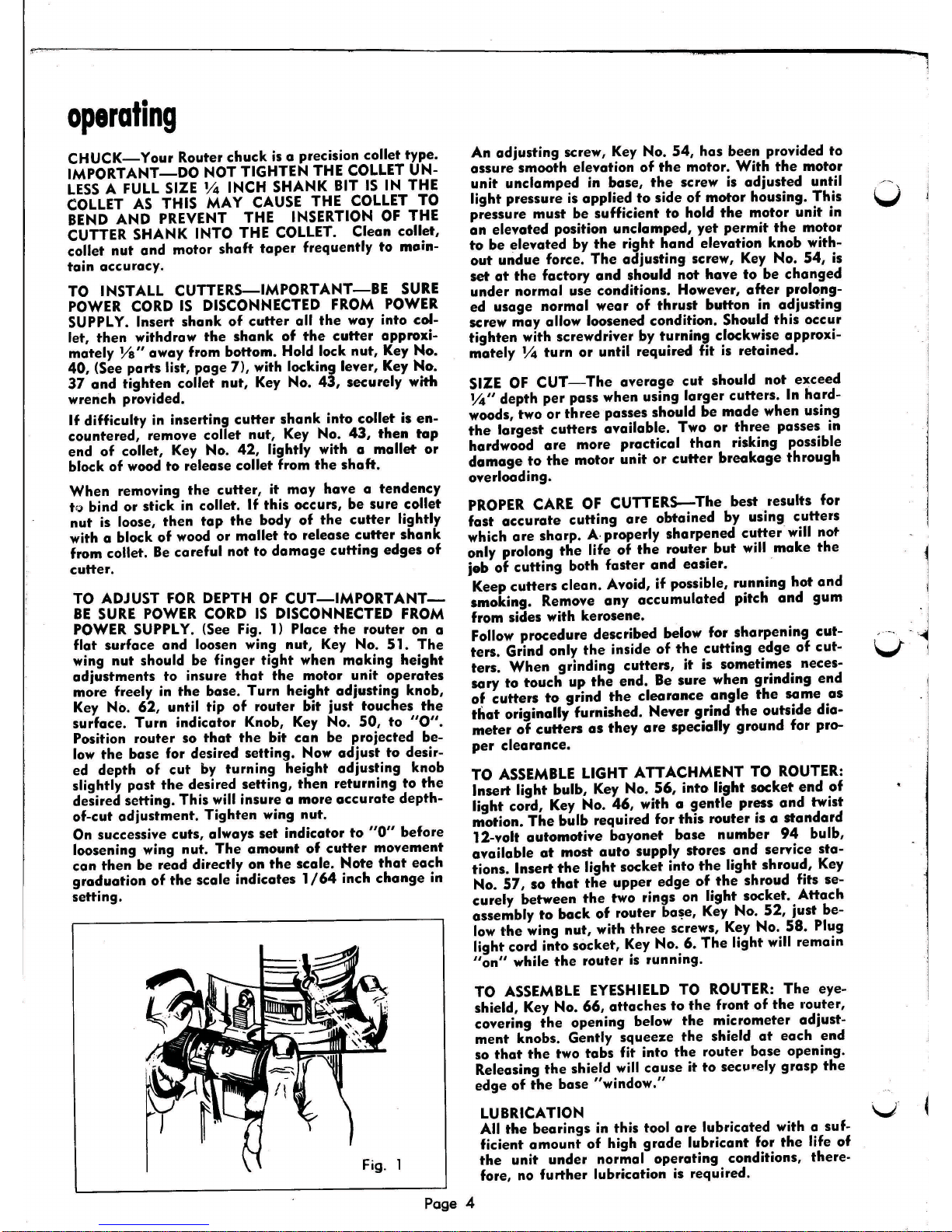
TO ADJUST FOR DEPTH OF CUT-IMPORT ANT-
BE SURE POWER CORD IS DISCONNECTED FROM
POWER SUPPLY. (See Fig. 1) Place the router on a
flat surface and loosen wing nut, Key No. 51. The
wing nut should be finger tight when making height
adjustments to insure that the motor unit operates
more freely in the base. Turn height adjusting knob,
Key No. 62, until tip of router bit just touches the
surface. Turn indicator Knob, Key No. 50, to
"0".
Position router so that the bit can be projected be-
low the base for desired setting. Now adjust to desir-
ed depth of cut by turning height adjusting knob
slightly past the desired setting, then returning to the
desired setting. This will insure a more accurate depth-
of-cut adjustment. Tighten wing nut.
On successive cuts, always set indicator to "0" before
loosening wing nut. The amount of cutter movement
can then be read directly on the scale. Note that each
graduation of the scale indicates 1/64 inch change in
setting.
Fig. 1
An adjusting screw, Key No. 54, has been provided to
assure smooth elevation of the motor. With the motor
unit unclamped in base, the screw is adjusted until
light pressure is applied to side of motor housing. This
pressure must be sufficient to hold the motor unit in
an elevated position unclamped, yet permit the motor
to be elevated by the right hand elevation knob with-
out undue force. The adjusting screw, Key No. 54, is
set at the factory and should not have to be changed
under normal use conditions. However, after prolong-
ed usage normal wear of thrust button in adjusting
screw may allow loosened condition. Should this occur
tighten with screwdriver by turning clockwise approxi-
mately 1;4 turn or until required fit is retained.
SIZE OF CUT-The average cut should not exceed
1;4" depth per pass when using larger cutters. In hard-
woods, two or three passes should be made when using
the largest cutters available. Two or three passes in
hardwood are more practical than risking possible
damage to the motor unit or cutter breakage through
overloading.
PROPER CARE OF CUTTERS-The best results for
fast accurate cutting are obtained by using cutters
which are sharp. A. properly sharpened cutter will nof'
only prolong the life of the router but will make the
job of cutting both faster and easier.
Keep cutters clean. Avoid, if possible, running hot and
smoking. Remove any accumulated pitch and gum
from sides with kerosene.
Follow procedure described below for sharpening cut-
ters. Grind only the inside of the cutting edge of cut-
ters. When grinding cutters, it is sometimes neces-
sary ta touch up the end. Be sure when grinding end
of cutters to grind the clearance angle the same as
that originally furnished. Never grind the outside dia-
meter of cutters as they are specially ground far pro-
per clearonce.
TO ASSEMBLE LIGHT ATTACHMENT TO ROUTER:
Insert light bulb, Key No. 56, into light socket end of
light cord, Key No. 46, with a gentle press and twist
motion. The bulb required for this router is a standard
12-volt automotive bayonet base number 94 bulb,
available at most auto supply stores and service sta-
tions. Insert the light socket into the light shroud, Key
No. 57, so that the upper edge of the shroud fits se-
curely between the two rings on light socket. Attach
assembly to back of router ba~e, Key No. 52, just be-
low the wing nut, with three screws, Key No. 58. Plug
light cord into socket, Key No.6. The light will remain
"on" while the router is running.
TO ASSEMBLE EYESHIELD TO ROUTER: The eye-
shield, Key No. 66, attaches to the front of the I'outer,
covering the opening below the micrometer adjust-
ment knobs. Gently squeeze the shield at each end
so that the two tabs fit into the router base opening.
Releasing the shield will cause it to secl.lrely grasp the
edge of the base "window."
v
Page 4