Craftsman 917.203930 User manual

Operator's Manual
FIN°
LAWN TRACTO
22 HR* 54" Mower
Electric Start
Automatic Transmission
Model No.
917.20393
• EspaSol, p. 37
This product has a low emission engine which operates
differently from previously built engines. Before you start the
engine, read and understand this manual.
IMPORTANT:
Read and follow all Safety
Rules and Instructions before
operating this equipment.
For answers to your questions
about this product, call:
1-888-331-4569
Craftsman Customer Help Line
Sears Brands Management Corporation, Hoffman Estates, IL 60179 U.S.A.
Visit our Craftsman website: www.craftsman.com
* The power rating as declared by the engine manufacturer is the
average gross power output at the specified RPM of a typical
production engine for the engine model measured using SAE
Standards for engine gross power. Please refer to the engine
manufacturer for details.
* La potencia nominal declarada por el fabricante del motor es la
salida media de potencia bruta a las RPM especificadas de un
motor de serie tipico para el modelo de motor, medida segQn
las normas SAE sobre potencia bruta de motor. Para mas
informaci6n, consulte al fabricante del motor.
586149596 Rev. 3

Warranty ................................................ 2
Safety Rules .......................................... 3
Product Specifications ........................... 6
Assembly/Pre-Operation ....................... 7
Operation ............................................. 13
Maintenance Schedule ........................ 21
Maintenance ........................................ 21
Service and Adjustments ..................... 26
Storage ................................................ 31
Troubleshooting ................................... 32
Espar_o! ................................................ 37
Sears Service ........................ Back Cover
CRAFTSMAN FULL WARRANTY
FOR TWO YEARS from the date of purchase, all non-expendable parts of this riding equipment are
warranted against any defects in material or workmanship. A defective non-expendable part will receive
free in-home repair or replacement if repair is unavailable.
BATTERY LIMITED WARRANTY
FOR 90 DAYS from the date of purchase, the battery (an expendable part) of this riding equipment is
warranted against any defects in material or workmanship. A new battery will be supplied free of charge.
You are responsible for the labor cost of battery installation.
ADDITIONAL LIMITED WARRANTIES
In the following additional warranties, you are responsible for the labor cost of part installation after
the second year from the date of purchase.
FOR FIVE YEARS from the date of purchase, the frame of this riding equipment is warranted against any
defects in material or workmanship. A new frame will be supplied free of charge.
FOR TEN YEARS from the date of purchase, the front axle of this riding equipment is warranted against any
defects in material or workmanship. A new front axle will be supplied free of charge.
FOR AS LONG AS IT IS USED by the original owner after the tenth year from the date of purchase, the
cast iron front axle (if equipped) of this riding equipment is warranted against any defects in material or
workmanship. With proof of purchase, a new cast iron front axle will be supplied free of charge.
WARRANTY SERVICE
For warranty coverage details to obtain free repair or replacement, call 1-888-331-4569 or visit the web
page: www.craftsman, com/warranty
In all cases above, if part repair or replacement is impossible, the riding equipment will be replaced free of
charge with the same or an equivalent model.
All of the above warranty coverage is void if this riding equipment is ever used while providing commercial
services or if rented to another person.
This warranty covers ONLY defects in material and workmanship. Warranty coverage does NOT
include:
• Expendable parts (except battery) that can wear out from normal use within the warranty period, including
but not limited to blades, spark plugs, air cleaners, belts, and oil filters.
• Standard maintenance servicing, oil changes, or tune-ups.
• Tire replacement or repair caused by punctures from outside objects, such as nails, thorns, stumps, or
glass.
• Tire or wheel replacement or repair resulting from normal wear, accident, or improper operation or
maintenance.
• Repairs necessary because of operator abuse, including but not limited to damage caused by towing
objects beyond the capability of the riding equipment, impacting objects that bend the frame, axle
assembly or crankshaft, or over-speeding the engine.
• Repairs necessary because of operator negligence, including but not limited to, electrical and mechanical
damage caused by improper storage, failure to use the proper grade and amount of engine oil, failure
to keep the deck clear of flammable debris, or failure to maintain the riding equipment according to the
instructions contained in the operator's manual.
• Engine (fuel system) cleaning or repairs caused by fuel determined to be contaminated or oxidized
(stale). In general, fuel should be used within 30 days of its purchase date.
• Normal deterioration and wear of the exterior finishes, or product label replacement.
This warranty gives you specific legal rights, and you may also have other rights which vary from state to
state.
Sears Brands Management Corporation, Hoffman Estates, IL 60179
2

,_DANGER: This cutting machine is capable of amputating hands and feet and
throwing objects. Failure to observe the following safety instructions could result
in serious injury or death.
_,WARNING: In order to prevent acciden-
tal starting when setting up, transporting,
adjusting or making repairs, always discon-
nect spark plug wire and place wire where
it cannot contact spark plug.
_,WARNING: Do not coast down a hill in
neutral, you may lose control of the tractor.
_,WARNING: Tow only the attachments
that are recommended by and comply with
specifications of the manufacturer of your
tractor. Use common sense when towing.
Operate only at the lowest possible speed
when on a slope. Too heavy of a load, while
on a slope, is dangerous. Tires can lose
traction with the ground and cause you to
lose control of your tractor.
_,WARNING: Engine exhaust, some of
its constituents, and certain vehicle compo-
nents contain or emit chemicals known to
the State of California to cause cancer and
birth defects or other reproductive harm.
_,WARNING: Battery posts, terminals and
related accessories contain lead and lead
compounds, chemicals known to the State of
California to cause cancer and birth defects
or other reproductive harm. Wash hands
after handling.
I. CHILDREN
_,WARNING! CHILDREN CAN BE IN-
JURED BYTHIS EQUIPMENT. TheAmeri-
can Academy of Pediatrics recommends
that children be a minimum of 12 year of
age before operating a pedestrian controlled
lawn mower and a minimum of 16 years of
age before operating a riding lawn mower.
_IbWARNING! CHILDREN CAN BE
SERIOUSLY INJURED OR KILLED BY
THIS EQUIPMENT. Carefully read and
follow all of the safety instructions below.
Tragic accidents can occur if the operator
is not alert to the presence of children.
Children are often attracted to the machine
and the mowing activity. Never assume
that children will remain where you last
saw them.
• Keep children out of the mowing area
and in the watchful care of a responsible
adult other than the operator.
• Be alert and turn machine off if a child
enters the area.
• Before and while backing, look behind
and down for small children.
• Never carry children, even with the
blades shut off. They may fall off and
be seriously injured or interfere with safe
machine operation. Children who have
been given rides in the past may suddenly
appear in the mowing area for another
ride and be run over or backed over by
the machine.
• Never allow children to operate the ma-
chine.
• Use extreme caution when approaching
blind corners, shrubs, trees, or other
objects that may block your view of a
child.
li.
o
GENERAL OPERATION
Read, understand, and follow all instruc-
tions on the machine and in the manual
before starting.
• Do not put hands or feet near rotating
parts or under the machine. Keep clear
of the discharge opening at all times.
• Only allow responsible adults, who are
familiar with the instructions, to operate
the machine.
• Clear the area of objects such as rocks,
toys, wire, etc., which could be picked
up and thrown by the blades.
• Ensure the area is clear of bystanders
before operating. Stop machine ifanyone
enters the area.
• Never carry passengers.
• Do not mow in reverse unless absolutely
necessary. Always look down and behind
before and while backing.
• Never direct discharged materialtoward
anyone. Avoid discharging material
against a wall or obstruction. Material
may ricochet back toward the operator.
Stop the blades when crossing gravel
surfaces.
• Do notoperate machinewithouttheentire
grass catcher, discharge chute, or other
safety devices in place and working.
3

• Slow down before turning.
• Never leave a running machine unat-
tended. Always turn off blades, set
parking brake, stop engine, and remove
keys before dismounting.
• Disengage blades when not mowing.
Shut off engine and wait for all parts to
come to a complete stop before cleaning
the machine, removing the grass catcher,
or unclogging the discharge chute.
• Operate machine onlyin daylight or good
artificial light.
• Do not operate the machine while under
the influence of alcohol or drugs.
• Watch for traffic when operating near or
crossing roadways.
• Use extreme caution when loading or
unloading the machine into a trailer or
truck.
• AIways wear eye protection when operat-
ing machine.
• Use ear protectors to avoid damage to
hearing.
• Data indicates that operators, age 60
years and above, are involved in a large
percentage of riding mower-related inju-
ries. These operators should evaluate
their ability to operate the riding mower
safely enough to protect themselves and
others from serious injury.
• Followthemanufacturer'srecommenda-
tion for wheel weights or counterweights.
• Keep machine free of grass, leaves or
other debris build-up which can touch hot
exhaust /engine parts and burn. Do not
allow the mower deck to plow leaves or
other debris which can cause build-up
to occur. Clean any oil or fuel spillage
before operating or storing the machine.
Allow machine to cool before storage.
Iii. SLOPE OPERATION
,d_,WARNING! When loading or unloading
this machine, do not exceed the maximum
recommended operation angle of 15 °.
Slopes are a major factor related to loss of
control and tip-over accidents, which can
result in severe injury or death. Operation
on all slopes requires extreme caution. If
you cannot back up the slope or if you feel
uneasy on it, do not mow it.
• Mow up and down slopes, not across.
• Watch for holes, ruts, bumps, rocks, or
other hidden objects. Uneven terrain
could overturn the machine. Tall grass
can hide obstacles.
• Choose a low ground speed so that you
will not have to stop or shift while on the
slope.
• Do not mow on wet grass. Tires may
lose traction. Always keep the machine
in gear when going down slopes.
• Do not shift to neutral and coast downhill.
• Avoid starting, stopping, or turning on a
slope. Ifthetires Iosetraction, disengage
the blades and proceed slowly straight
down the slope.
• Keep all movement on the slopes slow
and gradual. Do not make sudden
changes in speed or direction, which
could cause the machine to roll over.
• Use extreme caution while operating
machine with grass catchers or other
attachments; they can affect the stabil-
ity of the machine. Do no use on steep
slopes.
• Do not try to stabilize the machine by
putting your foot on the ground.
• Do not mow near drop-offs, ditches,
or embankments. The machine could
suddenly roll over if a wheel is over the
edge or if the edge caves in.
• If machine stops while going uphill,
disengage blades, shift into reverse and
back down slowly.
• Do not turn on slopes unless necessary,
and then, turn slowly and gradually
downhill, if possible.
IV. TOWING
oTow only with a machine that has a hitch
designed for towing. Do not attach towed
equipment except at the hitch point.
• Followthemanufacturer'srecommenda-
tion for weight limits for towed equipment
and towing on slopes.
• Never allow children or others in or on
towed equipment.
• On slopes, the weight ofthetowed equip-
ment may cause loss of traction and loss
of control.
• Travel slowly and allow extra distance to
stop.
4

V. SERVICE
SAFE HANDLING OF GASOLINE
To avoid personal injury or property dam-
age, use extreme care in handling gasoline.
Gasoline is extremely flammable and the
vapors are explosive.
• Extinguish all cigarettes, cigars, pipes,
and other sources of ignition.
• Use only approved gasoline container.
• Never remove gas cap or add fuel with
the engine running.
• Allow engine to cool before refueling.
• Never fuel the machine indoors.
• Neverstorethe machine orfuel container
where there is an open flame, spark, or
pilot light such as on a water heater or
other appliances.
• Never fill containers inside a vehicle or
on a truck or trailer bed with plastic liner.
Always place containers on the ground
away from your vehicle when filling.
• Remove gas-powered equipment from
the truck or trailer and refuel it on the
ground. If this is not possible, then refuel
such equipment with a portable container,
rather than from a gasoline dispenser
nozzle.
• Keep the nozzle in contact with the rim
of the fuel tank or container opening at
all times until fueling is complete. Do not
use a nozzle lock-open device.
• Iffuelis spilled on clothing, change cloth-
ing immediately.
• Never overfill fuel tank. Replace gas cap
and tighten securely.
GENERALSERVICE
• Never operate machine in a closed area.
• Keepall nutsand boltstighttoensurethe
equipment is in safe working condition.
• Nevertamperwithsafetydevices. Never
interfere with the intended function of a
safety device or reduce the protection
provided by a safety device. Checkthere
proper operation regularly. NEVER oper-
ate a machine with a safety device that
does not function properly.
• Keep machine free of grass, leaves, or
other debris build-up. Clean oil or fuel
spillage and remove any fue!-soaked
debris. Allow machine to cool before
storing.
• If you strike a foreign object, stop and
inspectthe machine. Repair, if necessary,
before restarting.
• Never make any adjustments or repairs
with the engine running.
• Checkgrasscatchercomponentsandthe
discharge chute frequently and replace
with manufacturer's recommended parts,
when necessary.
• Mower blades are sharp. Wrapthe blade
or wear gloves, and use extreme caution
when servicing them.
• Check brake operation frequently. Adjust
and service as required.
• Maintain orreplace safetyand instruction
labels, as necessary.
Use ear protectors to avoid damage to hearing.
Always wear eye protection when operating machine.
5

PRODUCT SPECIFICATIONS
Gasoline Capacity 3.0 Gallons/11,35 L
and type: Regular Unleaded*
Oil Type: SAE 10W30 (above32°F/0°C)
(API: SG-SL) SAE 5W30 (below 32°F/0°0)
Oil Capacity: W/Filter: 64 Oz./1,89 L
W/out Filter: 60 Oz./1,77 L
Spark Plug: Champion 24 132 03
(Gap: .030"/0.76 mm)
Charging System: 15 Amps @ 3600 RPM
Battery: Amp/Hr: 28
Min. CCA: 230
Case size: U1R
Blade Bolt Torque: 45-55 Ft. Lbs./62-75 Nm
&Gasoline containing up to 10% ethanol (El0) is
acceptable for use in this machine. The use of
any gasoline exceeding 10% ethanol (El0) will
void the product warranty.
CONGRATULATIONS on your purchase of
a new tractor. It has been designed, engi-
neered and manufactured to give you the best
possible dependability and performance.
Should you experience any problem you can-
not easily remedy, please contact a Sears or
other qualified service center. We have com-
petent, well-trained representatives and the
proper tools to service or repair this tractor.
Please read and retain this manual. The
instructions will enable you to assemble
and maintain your tractor properly. Always
observe the "SAFETY RULES".
CUSTOMER RESPONSIBILITIES
• Read and observe the safety rules.
• Follow a regular schedule in maintaining,
caring for and using your tractor.
• Follow instructions under "Maintenance"
and "Storage" sections of this manual.
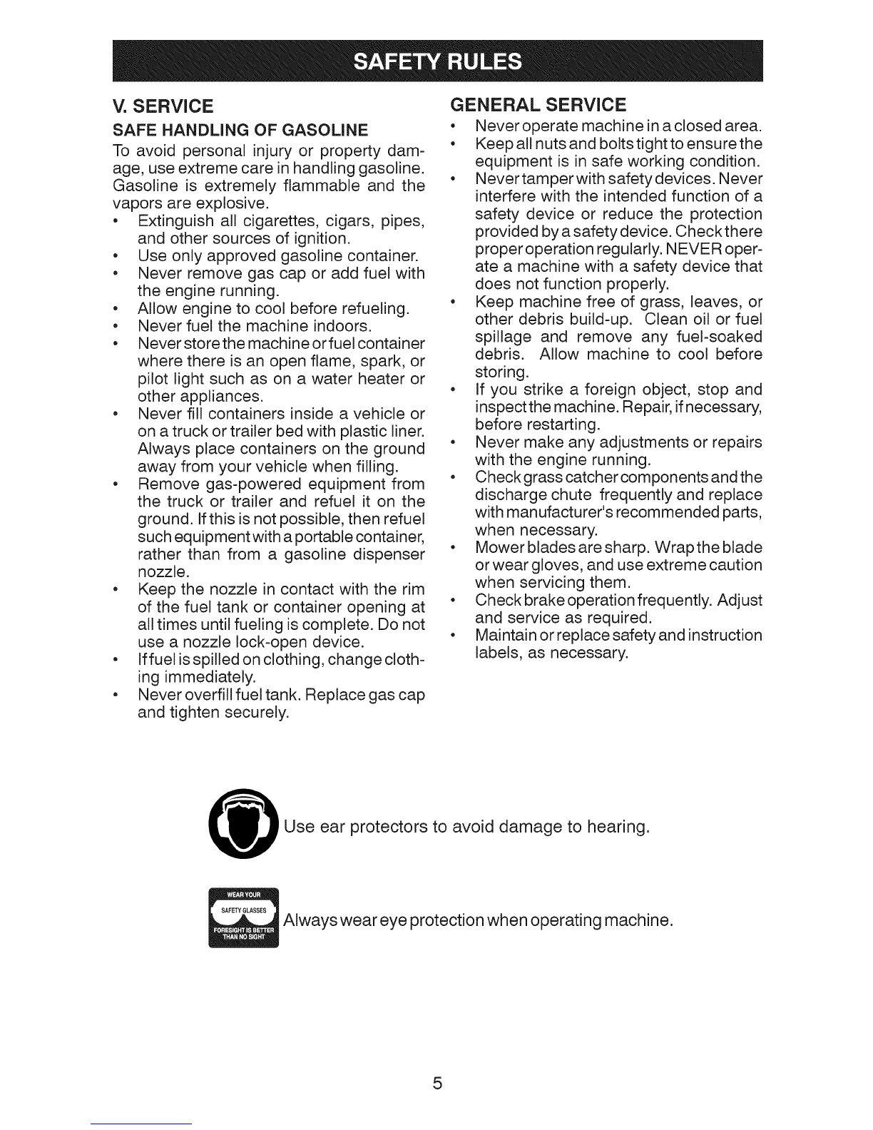
• Wear proper Personal Protective Equip-
ment (PPE) while operating this machine,
including (at a minimum) sturdy footwear,
eye protection, and hearing protection.
Do not mow in shorts and/or open toed
footwear.
• Always let someone know you are outside
mowing.
_IbWARNING: This tractor is equipped with
an internal combustion engine and should
not be used on or near any unimproved
forest-covered, brush-covered or grass-
covered land unless the engine's exhaust
system is equipped with a spark arrester
meeting applicable local or state laws (if
any). If a spark arrester is used, it should
be maintained in effective working order by
the operator.
In the state of Californiathe above is required
by law (Section 4442 of the California Public
Resources Code). Other states may have
similar laws. Federal laws apply on federal
lands. A spark arrester for the muffler is
available through your nearest Sears service
center (See REPAIR PARTS manual).
REPAIR PROTECTION AGREEMENTS
Congratulations on making a smart pur-
chase. Your new Craftsman® product is
designed and manufactured for years of
dependable operation. But like all products,
it may require repair from time to time. That's
when having a Repair Protection Agreement
can save you money and aggravation.
Purchase a Repair Protection Agreement
now and protect yourself from unexpected
hassle and expense.
Here's what's included in the Agreement:
• Expert service by our 12,000 professional
repair specialists.
Unlimited service and no charge for parts
and labor on all covered repairs.
Product replacement if your covered
product can't be fixed.
Discount of 25% from regular price of
service and service-related parts not
covered bythe agreement; also, 25% off
regular price of preventive maintenance
check.
Fast help by phone - phone support
from a Sears representative on products
requiring in-home repair, plus convenient
repair scheduling.
Once you purchase the Agreement, a simple
phone call is all that it takes for you to sched-
ule service. You can call anytime day or night,
or schedule a service appointment online.
Sears has over 12,000 professional repair
specialists, who have access to over 4.5
million quality parts and accessories. That's
the kind of professionalism you can count on
to help prolong the life of your new purchase
for years to come. Purchase your Repair
Protection Agreement today!
Some limitations and exclusions apply.
For prices and additional information call
1-800-827=6655.
SEARS INSTALLATION SERVICE
For Sears professional installation of home
appliances, garage door openers, water
heaters, and other major home items, in the
U.S.A. call 1-800=4-MY=HOME®.
6

Mower
(2) Rear
Lift Link _
(5) 1-3/16 Assemblies
O.D.Washers
(1) Small
Retainer Springs
(5) Large
Retainer Springs
(1) Front
Lift Link
Assembly
Mower Front Wheel
(1) Shoulder Bolt
(1) Wheel
©
(1) 1-1/40.D.
Washer
©
(1) 3/8-16
Locknut
if Equipped
(1) Anti-Sway Bar (1) 3/40.D.
Washers (1) Srnall Retainer
Springs
Keys
(2) Keys
(1) Oil Drain Tube
(1) Quick Connect
Slope Sheet
Your new tractor has been assembled at the factory with exception of those parts left
unassembled for shipping purposes. To ensure safe and proper operation of your tractor
all parts and hardware you assemble must be tightened securely. Use the correct tools
as necessary to ensure proper tightness.
TOOLS REQUIRED FOR ASSEMBLY
A socket wrench set will make assembly
easier. Standard wrench sizes are listed.
TO REMOVE TRACTOR
CARTON
UNPACK CARTON
FROM
(2) 7/16" wrenches Utility knife
(1) 1/2" wrench Tire pressure gauge
(1) 3/4" wrench Pliers
(1) 3/4" socket w/drive ratchet
(1) 9/16" wrench Flashlight
When right or left hand is mentioned in this
manual, itmeans when you are inthe operating
position (seated behind the steering wheel).
•Remove all accessible loose parts and
parts cartons from carton.
•Cut along dotted lines on all four pan-
els of carton. Remove end panels and
lay side panels flat.
•Remove mower and packing materials.
•Check for any additional loose parts or
cartons and remove.
7

BEFORE REMOVING TRACTOR
FROM SKID
TO CHECK BATTERY
1. Lift hood to raised position.
NOTE: If this battery is put into service after
month and year indicated on label (label is
located between terminals) charge battery
for minimum of one hour at 6-10 amps. (See
"BATTERY" in Maintenance section of this
manual for charging instructions).
• For batteryand battery cable installation
see "REPLACING BATTERY" in the
"Service and Adjustments" section in this
manual.
LABEL
ADJUST SEAT
1. Sit in seat.
2. Lift up adjustment lever (A) and slide seat
until a comfortable position is reached
which allows you to press clutch/brake
pedal all the way down.
3. Release lever to lock seat in position.
NOTE: You may now roll your tractor offthe
skid. Continue using the instructions that
follow to remove the tractor from the skid.
WARNING: Before starting, read, un-
derstand and follow all instructions in the
Operation section of this manual. Be sure
tractor is in a well-ventilated area. Be sure
the area in front of tractor is clear of other
people and objects.
TO ROLL TRACTOR OFF SKID (See
Operation section for location and
function of controls)
1. Raise attachment lift lever to its highest
position.
2. Release parking brake by depressing
clutch/brake pedal.
3. Place freewheel control in "transmission
disengaged position" (See "TO TRANS-
PORT" in the Operation section of this
manual).
4. Roll tractor forward off skid.
Continue with the instructions that follow.
TO INSTALL MOWER
1. SET PARKING BRAKE LEVER AND
LOWER ATTACHMENT LIFT LEVER
• Depress clutch/brake pedal all the way
down and hold.
• Pull parking brake lever up and hold,
release pressure from clutch/brake
pedal, then release parking brake lever.
Pedal should remain in brake position.
Ensure parking brake will hold tractor
secure.
ParkingBrake Lever
I \__L
8

_,CAUTION: Lift lever is spring loaded.
Have a tight grip on lift lever, lower it slowly
and engage in lowest position. Lift lever is
located on left side of fender.
2. ASSEMBLE FRONT GAUGE WHEEL
(W) TO FRONT OF MOWER
H, Front Mower Bracket
W, Front Gauge Wheel
X. Shoulder Bolt
Y, 1-1/40.D. Washer
Z, 3/8-16 Locknut
3. TURN STEERING WHEEL LEFT AND
POSITION MOWER
• Turn steering wheel to the left as far as it
will go and position mower on right side of
tractor with deflector shield (Q) to the rig ht.
Front
Back
fEngine
d
i - - /
Transaxle
Q. Deflector Shield
4. SLIDE MOWER UNDER TRACTOR
• Bring belt forward and check belt for pro-
per routing in all mower pulley grooves.
NOTE: Be sure mower side suspension
arms (A) are pointing forward before sliding
mower under tractor.
• Slide mower under tractor until it is
centered under tractor.
A. Mower Side Suspension Arms
B. Retainer Spring
C. Rear Lift Link(s)
D. Right Side Rear Mower Bracket
E. Front Lift Link Assembly
R Front Suspension Bracket
H, Front Mower Bracket
9
I. Left Side Rear Mower Bracket
K. Belt Tension Rod
L, Locking Bracket
M, Engine Clutch Pulley
Q, Deflector Shield
S, Anti-Sway Bar
W, Front Gauge Wheel

A. MowerSideSuspensionArms
Q. DeflectorShield
5. INSTALL ANTI-SWAY BAR (S)
(IF EQUIPPED)
ANTI-SWAY BAR (S)
_ Towards Towards
Transaxle Mower Deck _"
90° End Integrated Washer End
From right side of mower, first insert
90 ° end of anti-sway bar (S) into hole in
transaxle bracket (T), located near left
rear tire in front of transaxle.
NOTE: Depending on model, bracket (T) may
be different than shown but hole for anti-sway
bar will be in same position/location.
• Pivot the integrated washer end of anti-
sway bar (S) towards mower deck bracket
on right side of mower. Insert integrated
washer end of bar into hole in rear mower
bracket (D). Move mower as needed to
insert integrated washer end of bar into
rear mower bracket (D).
• Secure with small washer and small
retainer spring as shown.
6. ATTACH MOWER SIDE SUSPENSION
ARMS (A) TO CHASSIS
• Position front hole in side suspension arm
(A) over pin on outside of tractor chassis
and secure with large washer and large
retainer spring (B).
• Repeat on opposite side of tractor.
A,
B.
D.
S
I
Mower Side Suspension Arms
Retainer Spring
Right Side Rear Mower Bracket
7. ATTACH REAR LIFT LINKS (C)
• Insert rod end of rear lift link (C) into hole
(U) in tractor lift shaft suspension arm
and pivot link down to mower.
• Lift rear corner of mower and position slot
in link assembly over pin on rear mower
bracket (D) and secure with large washer
and large retainer spring.
• Repeat on opposite side of tractor.
10

m
\
C. Rear Lift Link(s)
D. Right Side Rear Mower Bracket
'U. Hole
ATTACH FRONT LINK (E)
• Turn steering wheel to position wheels
straight forward.
• From front of tractor, insert rod end of
front link (E) through front hole in tractor
front suspension bracket (F).
• Move to left side of mower and and insert
large retainer spring (G) through hole in
front link (E) behind front suspension
bracket (F).
• Insert other end of link (E) into hole in
front mower bracket (H) and secure with
washer and small retainer spring (J).
NOTE: Requires deck lifting.
8
9 INSTALL BELT ON ENGINE CLUTCH
PULLEY (M)
• Disengage belt tension rod (K) from
locking bracket (L).
• Install belt onto engine clutch pulley (M).
M,Engine
Clutch Pulley
IMPORTANT: Check belt for proper routing
in all mower pulley grooves and under
mandrel covers.
• Engage belt tension rod (K) on locking
bracket (L).
_CAUTION: Belt tension rod is spring
loaded. Have a tight grip on rod and engage
slowly.
• Raise attachment lift lever to highest
position.
• If necessary, adjust gauge wheels
before operating mower as shown in the
Operation section of this manual.
MOWER DRIVE BELT INSTALLATION
Follow procedure described in "TO
REPLACE MOWER BLADE DRIVE BELT"
in the "Service and Adjustments" section of
this manual.
E. Front Lift Link Assembly
R Front Suspension Bracket
G, Large Retainer Spring
H, Front Mower Bracket
J. Small Retainer Spring
M, Engine Clutch Pulley
11

CHECK TIRE PRESSURE
The tires on your tractor were overinflated at
the factory for shipping purposes. Correct
tire pressure is important for best cutting
performance.
• Reduce tire pressure to PSI shown on
tires.
CHECK DECK LEVELNESS
For best cutting results, mower housing
should be properly leveled. See "TO LEVEL
MOWER" in the Service and Adjustments
section of this manual.
CHECK FOR PROPER POSITION OF
ALL BELTS
See the figures that are shown for replacing
motion and mower blade drive belts in the
Service and Adjustments section ofthis man-
ual. Verify that the belts are routed correctly.
CHECK BRAKE SYSTEM
After you learn how to operate your tractor,
check to see that the brake is operating prop-
erly. See "TO CHECK BRAKE" in the Service
and Adjustments section of this manual.
CHECKLIST
Before you operate your new tractor, we
wish to assure that you receive the best
performance and satisfaction from this
Quality Product.
Please review the following checklist:
_" All assembly instructions have been
completed.
_" No remaining loose parts in carton.
_" Battery is properly prepared and charged.
_" Seat is adjusted comfortably and tight-
ened securely.
_" All tires are properly inflated. (For ship-
ping purposes, the tires were overinflated
at the factory).
_" Be sure mower deck is properly leveled
side-to-side/front-to-rear for best cutting
results. (Tires must be properly inflated
for leveling).
_" Check mower and drive belts. Be sure
they are routed properly around pulleys
and inside all belt keepers.
_/" Check wiring. See that all connections are
still secure and wires are properlyclamped.
_/" Before driving tractor, be sure freewheel
control is in "transmission engaged" posi-
tion (see "To Transport" in the Operation
section of this manual).
While learning howto use your tractor, pay ex-
tra attention to the following important items:
_/" Engine oil is at proper level.
_/" Fuel tank is filled with fresh, clean, regular
unleaded gasoline.
_/" Become familiar with all controls, their
location and function. Operate them
before you start the engine.
Be sure brake system is in safe operating
condition.
v"
v" Be sure Operator Presence System and
Reverse Operation System (ROS) are
working properly (See the Operation and
Maintenance sections in this manual).
12

These symbols may appear on your tractor or in literature supplied with the product.
Learn and understand their meaning.
LOW CHOKE FAST SLOWREVERSE NEUTRAL HiGH iGNiTiON
SWITCH
ENGINE ENGINE ENGINE DiFFERENTiAL
OFF START ON LOCK CLUTCH/ MOWER
BRAKE PEDAL LiFT
PARKING MOWER
BRAKE HEIGHT
REVERSE REVERSE FORWARD
OPERATION
SYSTEM(ROB)
ATTACHMENT ATTACHMENT
CLUTCH CLUTCH
DISENGAGED ENGAGED
FREE WHEEL
(Automatic Models only)
Failure to follow instructions
could result in serious injury or
death. The safety alert symbol
is used to identify safety inform-
ation about hazards which can
result in death, serious injury
and/or property damage.
CRUISECONTROL
DANGER, KEEP
HANDS AND
FEET AWAY
&
,,h({((ik£()i,,
LIGHTSON FUEL
¢
BATTERY EAR
PROTECTION
REQUIRED
@@@@@
KEEPAREACLEAR SLOPE HAZARDS
(SEESAFETY RULESSECTION)
DANGER indicates a hazard which, if not avoided,
wiil result in death or serious injury.
WARNING indicates a hazard which, if not avoided,
could result in death or serious injury.
CAUTION indicates a hazard which, if not avoided,
might result in minor or moderate injury.
CAUTION when used without the alert symbol,
indicates a situation that could result in damage
to the tractor and/or engine.
HOT SURFACES indicatesa hazard which,
ifnot avoided, could result in death, serious
injury and/or property damage.
FIRE indicatesa hazard which, ifnot avoided,
could result in death, serious injury and/or
property damage.
13

KNOW YOUR TRACTOR
READ THIS MANUAL AND SAFETY RULES BEFORE OPERATING YOUR TRACTOR
Compare the illustrations with your tractor to familiarize yourself with the locations of
various controls and adjustments. Save this manual for future reference.
@ @
Our tractors conform to the applicable safety standards of the
American National Standards Institute.
(A) ATTACHMENT LIFT LEVER - Used to
raise and lower the mower or other attach-
ments mounted to your tractor.
(B) BRAKE PEDAL - Used for braking the
tractor and starting the engine.
(C) PARKING BRAKE - Locks clutch/brake
pedal into the brake position.
(D) THROTTLE CONTROL- Used to control
engine speed.
(E) ATTACHMENT CLUTCH SWITCH -
Used to engage the mower blades or other
attachments mounted to your tractor.
(F) IGNITION SWITCH - Used for starting
and stopping the engine.
(G) REVERSE OPERATION SYSTEM
(ROS) "ON" POSITION - Allows operation
of mower or other powered attachment while
in reverse.
(H) LIGHT SWITCH - Turns the headlights
on and off.
(J) CRUISE CONTROL LEVER - Used to set
forward movement oftractor at desired speed
without holding the forward drive pedal.
(K) FORWARD DRIVE PEDAL - Used for
forward movement of tractor.
(L) REVERSE DRIVE PEDAL - Used for
reverse movement of tractor.
(M) FREEWHEEL CONTROL- Disengages
transmission for pushing or slowly towing
the tractor with the engine off.
(N) CHOKE CONTROL- Used when starting
a cold engine.
(P) SERVICE MINDER/HOUR METER-
Indicates when service is required for the
engine and mower.
14

|=
The operation of any tractor can result in foreign objects thrown into I
the eyes, which can result in severe eye damage. Always wear safety !
glasses or eye shields while operating your tractor or performing any_
adjustments or repairs. We recommend standard safety glasses or a_
wide vision safety mask worn over spectacles. J
HOW TO USE YOUR TRACTOR
TO SET PARKING BRAKE
Your tractor is equipped with an operator
presence sensing switch. When engine is
running, any attempt bythe operator to leave
the seat without first setting the parking brake
will shut off the engine.
1. Depress brake pedal (B) all the way down
and hold.
2. Pull parking brake lever (C) up and hold,
release pressure from brake pedal (B),
then release parking brake lever. Pedal
should remain in brake position. Make
sure parking brake will hold tractor secure.
STOPPING
ENGINE -
• Movethrottle control (D) between half and
full speed (fast) position.
NOTE: Failure to move throttle control be-
tween half and full speed (fast) position, be-
fore stopping, maycause engineto "backfire".
• Turn ignition key (F) to "STOP" position
and remove key. Always remove key when
leaving tractorto prevent unauthorized use.
• Never use choke to stop engine.
IMPORTANT: Leaving the ignition switch in
any position other than "STOP" will cause the
battery to discharge and go dead.
NOTE: Under certain conditions when tractor
is standing idle with the engine running, hot
engine exhaust gases may cause "brown-
ing" of grass. To eliminate this possibility,
always stop engine when stopping tractor
on grass areas.
AI_CAUTION: Always stop tractor com-
pletely, as described above, before leaving
the operator's position.
MOWER BLADES -
, To stop mower blades, move attachment
clutch control to disengaged position (¢_).
TO USE THROTTLE CONTROL (D)
Always operate engine at full speed (fast).
• Operating engine at less than full speed
(fast) reduces engine's operating effi-
ciency.
• Full speed (fast) offers the best mower
performance.
(t_l) Attachment (t_) Attachment
Clutch Control Clutch Control
"Engaged .... Disengaged"
GROUND DRIVE-
• To stop ground drive, depress brake pedal
all the way down.
IMPORTANT: Forward and reverse drive
pedals return to neutral position when not
depressed.
TO USE CHOKE CONTROL (N)
Use choke control whenever you are start-
ing a cold engine. Do not use to start a
warm engine.
• To engage choke control, pull knob out.
Slowly push knob in to disengage.
15

TOMOVE FORWARD AND BACKWARD
The direction and speed of movement
is controlled by the forward and reverse
drive pedals.
1. Start tractor and release parking brake.
2. Slowly depress forward (K) or reverse (L)
drive pedal to begin movement. Ground
speed increases the further down the
pedal is depressed.
TO USE CRUISE CONTROL
The cruise control feature can be used for
forward travel only.
SYSTEM CHARACTERISTICS
The cruise control should only be used
while mowing or transporting on relatively
smooth, straight surfaces. Other conditions
such as trimming at slow speeds may cause
the cruise control to disengage. Do not use
the cruise control on slopes, rough tertian
or while trimmimg or turning.
• With forward drive pedal (K) depressed to
desired speed, pull cruise control lever (J)
up and hold while lifting your foot off the
pedal, then release the lever.
To disengage the cruise control, depress the
brake pedal or tap on forward drive pedal.
TO ADJUST MOWER CUTTING HEIGHT
The position of the attachment lift lever (A)
determines the cutting height.
The cutting height range is approximately 1
to 4" (25,4 to 101,6 mm). The heights are
measured from the ground to the blade tip
with the engine not running. These heights
are approximate and may vary depending
upon soil conditions, height of grass and
types of grass being mowed.
• The average lawn should be cutto approxi-
mately 2-1/2" (63,5 mm) during the cool
season and to over 3" (76,2 mm) during
hot months. For healthier and better look-
ing lawns, mow often and after moderate
growth.
• For best cutting performance, grass over
6" (152,4 mm) in height should be mowed
twice. Make the first cut relatively high; the
second to desired height.
TO ADJUST GAUGE WHEELS
Gauge wheels are properly adjusted when
they are slightly offthe ground when mower
is at the desired cutting height in operating
position. Gauge wheels then keep the deck
in proper position to help prevent scalping
in most terrain conditions.
NOTE: Adjust gauge wheels with tractor on
a flat level surface.
1. Adjust mower to desired cutting height
(See "TO ADJUST MOWER CUTTING
HEIGHT" in this section of manual).
2. With mower in desired height of cut posi-
tion, gauge wheels should be assembled
so they are slightly offthe ground. Install
gauge wheel in appropriate hole. Tighten
securely.
3. Repeat for all, installing gauge wheel in
same adjustment hole.
9/16"
• Put attachment lift lever in desired cutting
height slot.
16

TO OPERATE MOWER
Your tractor is equipped with an operator
presence sensing switch. Any attempt
by the operator to leave the seat with the
engine running and the attachment clutch
engaged will shut off the engine. You must
remain fully and centrally positioned in the
seat to prevent the engine from hesitating or
cutting off when operating your equipment
on rough, rolling terrain or hills.
1. Select desired height of cut with attach-
ment lift lever.
2. Start mower blades by engaging attach-
ment clutch control.
TO STOP MOWER BLADES
Disengage attachment clutch control.
_,CAUTION: Do not operate the mower
without either the entire grass catcher, on
mowers so equipped, or the deflector shield
in place.
J
REVERSE OPERATION SYSTEM (ROS)
Your tractor is equipped with a Reverse
Operation System (ROS). Any attempt by
the operator to travel in the reverse direction
with the attachment clutch engaged will shut
off the engine unless ignition key is placed
in the ROS "ON" position.
_,WARNING: Backing up with the at-
tachment clutch engaged while mowing is
strongly discouraged. Turning the ROS "ON",
to allow reverse operation with the attach-
ment clutch engaged, should only be done
when the operator decides it isnecessary to
reposition the machine with the attachment
engaged. Do not mow in reverse unless
absolutely necessary.
USING THE REVERSE OPERATION
SYSTEM -
Only use if you are certain no children or
other bystanders will enter the mowing area.
1. Depress brake pedal all the way down.
2. With engine running, turn ignition key
counterclockwise to ROS "ON" position.
3. Look down and behind before and while
backing.
4. Slowly depress reverse drive pedal to
start movement.
5. When use ofthe ROS is no longer needed,
turn the ignition key clockwise to engine
"ON" position.
ROS "ON" Position Engine "ON" Position
(Normal Operating)
TO OPERATE ON HILLS
,_WARNING: Do not drive up or down
hills with slopes greater than 15 ° and do not
drive across any slope. Use the slope guide
provided at the back of this manual.
• Choose the slowest speed before start-
ing up or down hills.
• Avoid stopping orchanging speed on hills.
• If stopping is absolutely necessary, push
brake pedal quickly to brake position and
engage parking brake.
• To restart movement, slowly release park-
ing brake and brake pedal.
• Slowly depress appropriate drive pedal to
slowest setting.
• Make all turns slowly.
17

TOTRANSPORT
When pushing or towing your tractor, ensure
transmission is disengaged by placing free-
wheel control in freewheeling position. Free
wheel control is located at the rear drawbar
of tractor.
1. Raise attachment lift to highest position
with attachment lift control.
2. Pull freewheel control out until the free
wheel control rod locks in extended posi-
tion.
3. Do not push or tow tractor at more than
two (2) mph (3,2 km/h).
4. To reengage transmission, reverse above
procedure.
NOTE: Freewheel control will automatically
disengage when the brake/clutch pedal is
depressed.
Transmission Engaged
Transmission Disengaged
NOTE: To protect hood from damage when
transporting you rtractor on atruck or atrailer,
ensure hood is closed and secured to tractor.
Use an appropriate means of tying hood to
tractor (rope, cord, etc.).
TOWING CARTS AND OTHER ATTACH=
MENTS
Tow only the attachments that are recom-
mended by and comply with specifications
of the manufacturer of your tractor. Use
common sense when towing. Too heavy of
a load, while on a slope, is dangerous. Tires
can lose traction with the ground and cause
you to lose control of your tractor.
SERVICE MINDER/HOUR METER
Service minder shows the total number of
hours the engine has run and indicates when
the engine or mower needs servicing. After
every 50 hours of operation the oil can icon
will stay on for 2 hours or until a manual reset
occurs. To reset the display manually turn
the ignition switch to the on position, then
the off position five times (1 second on, 1
second off). To service engine and mower,
see the Maintenance section of this manual.
NOTE: Service minder runs when the ignition
key is in any position but "STOP". For
accurate reading, be sure key remains in the
"STOP" position when engine is not running.
BEFORE STARTING THE ENGINE
CHECK ENGINE OIL LEVEL
The engine in your tractor has been shipped
from the factory already filled with summer
weight oil.
1. Check engine oil with tractor on level
ground.
2. Pull up and remove oil fill cap/dipstick;
wipe oil off. Reinsert the dipstick into the
tube and push down firmly into place.
Remove and read oil level. If necessary,
add oil until "FULl" mark on dipstick is
reached. Do not overfill.
• For cold weather operation you should
change oil for easier starting (See the oil
viscosity chart in the Maintenance section
of this manual).
• Tochangeengineoil, seethe Maintenance
section in this manual.
ADD GASOLINE
• Fill fuel tank to bottom of filler neck. Do
not overfill. Use fresh, clean, regular
gasoline with a minimum of 87 octane.
Do not mix oil with gasoline. Purchase
fuel in quantities that can be used within
0 days to ensure fuel freshness.
CAUTION: Wipe off any spilled oil or fuel.
Do not store, spill or use gasoline near an
open flame.
IMPORTANT: When operating in tempera-
tures below 32°F (0°C), use fresh, clean
winter grade gasoline to help ensure good
cold weather starting.
18

CAUTION: Alcohol blended fuels (called
gasohol or using ethanol or methanol) can
attract moisture which leads to separation
and formation of acids during storage. Acidic
gas can damage the fuel system of an engine
while in storage. To avoid engine problems,
the fuel system should be emptied before
storage of 30 days or longer. Drain the gas
tank, start the engine and let it run until the
fuel lines and carburetor are empty. Use
fresh fuel next season. See Storage Instruc-
tions for additional information. Never use
engine or carburetor cleaner products in the
fuel tank or permanent damage may occur.
Fuel stabilizer is an acceptable alternative in
minimizing the formation of fuel gum deposits
during storage. Add stabilizer to gasoline in
fuel tank or storage container. Always follow
the mix ratio found on stabilizer container.
Run engine at least 10 minutes after adding
stabilizer to allow the stabilizer to reach the
carburetor. Do not empty the gas tank and
carburetor if using fuel stabilizer.
TO START ENGINE
When starting the engine for the first time or
if the engine has run out of fuel, it will take
extra cranking time to move fuel from the
tank to the engine.
1. Ensure freewheel control is in the trans-
mission engaged position.
2. Sit on seat in operating position, depress
brake pedal and set parking brake.
3. Move attachment clutch to disengaged
position.
4. Move throttle control to fast position
5. Pull choke control out for a cold engine
start attempt. For a warm engine start
attempt the choke control may not be
needed.
NOTE: Before starting, read the warm and
cold starting procedures below.
6. Insert key into ignition and turn key
clockwise to start position and release
key as soon as engine starts. Do not run
starter continuously for more than fifteen
seconds per minute. If the engine does
not start after several attempts, push
choke control in, wait a few minutes and
try again. If engine still does not start,
pull the choke control out and retry.
WARM WEATH E R STARTI NG
(50°F (10°C) and above)
7. When engine starts, slowly push choke
control in until the engine begins to run
smoothly. If the engine starts to run
roughly, pull the choke control out slightly
for a few seconds and then continue to
push the control in slowly.
• The attachments and ground drive
can now be used. If the engine does
not accept the load, restart the engine
and allow it to warm up for one minute
using the choke as described above.
COLD WEATHER STARTI NG
(50°F (10°C) and below)
7. When engine starts, slowly push choke
control in until the engine begins to run
smoothly. Continue to push the choke
control in small steps allowing the engine
to accept small changes in speed and
load, until the choke control is fully in.
If the engine starts to run roughly, pull
the choke control out slightly for a few
seconds and then continue to push the
control in slowly. This may require an
engine warm-up period from several
seconds to several minutes, depending
on the temperature.
AUTOMATIC TRANSMISSION WARM UP
Before driving the unit in cold weather, the
transmission should be warmed up as fop
lows:
1. Ensure the tractor is on level ground.
2. Release the parking brake and let the
brake slowly return to operating position.
3. Allow one minute for transmission to
warm up. This can be done during the
engine warm up period.
• The attachments can be used during
the engine warm-up period after the
transmission has been warmed up
and may require the choke control be
pulled out slightly.
19

MOWING TiPS
• DO NOT use tire chains when the mower
housing is attached to tractor.
• Mower should be properly leveled for best
mowing performance. See "TO LEVEL
MOWER HOUSING" in the Service and
Adjustments section of this manual.
• The left hand side of mower should be
used for trimming.
• Drive sothat clippings are discharged onto
the area that has already been cut. Have
the cut area to the right of the tractor. This
will result in a more even distribution of
clippings and more uniform cutting.
• When mowing large areas, start byturning
to the right so that clippings will discharge
away from shrubs, fences, driveways,
etc. After one or two rounds, mow in the
opposite direction making left hand turns
until finished.
., J
• If grass is extremely tall, it should be
mowed twice to reduce load and possible
fire hazard from dried clippings. Make
first cut relatively high; the second to the
desired height.
• Do not mow grass when it is wet. Wet
grass will plug mower and leave undesir-
able clumps. Allow grass to dry before
mowing.
• Always operate engine at full throttle
when mowing to assure better mow-
ing performance and proper discharge
of material. Regulate ground speed by
selecting a low enough gear to give the
mower cutting performance as well as the
quality of cut desired.
• When operating attachments, select a
ground speed that will suit the terrain and
give best performance of the attachment
being used.
20
Table of contents
Languages:
Other Craftsman Tractor manuals

Craftsman
Craftsman C459-60134 User manual

Craftsman
Craftsman 917.257572 User manual

Craftsman
Craftsman 917.257571 User manual

Craftsman
Craftsman 917.203920 User manual

Craftsman
Craftsman PGT9000 247.28984 User manual

Craftsman
Craftsman 917.204010 User manual

Craftsman
Craftsman 917.98644 User manual

Craftsman
Craftsman T100 Series User manual

Craftsman
Craftsman 917.99039 User manual

Craftsman
Craftsman 247.203730 User manual