56
ALMACENAMIENTO
Inmediatamente prepare su tractor para el alma-
cenamiento al final de la temporada o si el tractor
no se va a usar por 30 días o más.
ADVERTENCIA: Nunca almacene el tractor
con gasolina en el estanque dentro de un edificio
en donde los gases pueden alcanzar una llama
expuesta o una chispa. Permita que el motor se
enfríe antes de almacenarlo en cualquier recinto
privado.
TRACTOR
Remueva la segadora del tractor para el alma-
cenamiento por el invierno. Cuando la segadora
se va a almacenar por cierto período de tiempo,
límpiela cuidadosamente, quite toda la mugre,
la grasa, las hojas, etc. Guárdela en una área
limpia y seca.
1. Limpie todo el tractor (vea “LIMPIEZA” en la
sección de Mantenimiento en este manual).
2. Inspeccione y cambie las correas, si es nece-
sario (vea las instrucciones para el cambio de
las correas en la sección de Servicio y Ajustes
de este manual).
3. Lubríquelo, según se muestra en la sección
de Mantenimiento de este manual.
4. Asegúrese que todas las tuercas, los pernos y
los tornillos estén sujetados en forma segura.
Inspeccione las partes movibles para verificar
si hay daño, rotura o desgaste. Cámbielas si
es necesario.
5. Retoque todas superficies pintadas oxidadas
o picadas; aplique lija antes de pintar.
BATERÍA
• Cargue la batería completamente antes de
guardarla.
• Después de cierto período de tiempo en alma-
cenamiento, la batería puede necesitar volver
a cargarse.
• Para ayudar a evitar la corrosión y las fugas
de potencia durante largos períodos de alma-
cenamiento, se deben desconectar los cables
de la batería y se debe limpiar cuidadosamente
(vea “PARA LIMPIAR LA BATERÍA Y LOS TER-
MINALES” en la sección de Mantenimientode
este manual).
• Después de limpiarla, deje los cables desco-
nectados y póngalos en donde no puedan
entrar en contacto con los terminales de la
batería.
• Si se remueve la batería del tractor para el
almacenamiento, no la guarde directamente
sobre concreto o sobre superficies húmedas.
• Si la unidad está equipada con indicador de
batería/conector de carga, se puede adquirir
una unidad de carga opcional y conectarse
a la unidad para cargar la batería durante un
almacenamiento prolongado. Inspeccione y
limpie las terminales de la batería conforme sea
necesario antes de almacenarse durante un
tiempo prolongado con el cargador conectado.
MOTOR
SISTEMA DE COMBUSTIBLE
IMPORTANTE: Es important evitar que se
forman depositos de goma en partes funda-
mentales del sistema de combus-tible tales
como el carburador, el filtro del combustible,
la manguera del combustibles mezclados con
alcohol (conocido como gasohol o que tienen
etanol o metanol) pueden atraer humedad, lo
que conduce a la separación y a la formación
de acudos durante elalmacenamiento. La
gasolina acidica puede dañar el sistema de
combustible de un motor durante el periodo de
almacenamiento.
• Vaciar el depósito del carburante poniendo en
marcha el motor y dejándolo funcionar hasta
que el carburante termine el carburador esté
vacío.
• Nunca use los productos para limpieza del
carburador o del motor en el estanque de
combustible pues se pueden producir daños
permanentes.
• Use combustible nuevo la próxima temporada.
AVISO: El estabilizador de combustible es una
alternativa aceptable para reducir a un mínimo
la formación de depósitos de goma en el com-
bustible durante el período de almacenamiento.
Agregue estabilizador a la gasolina en el es-
tanque de combustible o en el envase para el
almacenamiento. Siempre siga la proporción de
mezcla que se encuentra en el envase del esta-
bilizador. Haga funcionar el motor por lo menos
10 minutos después de agregar el estabilizador,
para permitir que éste llegue al carburador. No
vaciar la gasolina del estanque de gasolina y el
carburador si se está usando estabilizador de
combustible.
ACEITE DEL MOTOR
Drene el aceite (con el motor caliente) y cámbielo
con aceite de motor limpio. (Vea “MOTOR” en
la sección de Mantenimiento” de este manual.)
CILINDRO(S)
1. Remueva la(s) bujía(s).
2. Vacíe 29.5 mL (1 Oz.) de aceite a través
del agujero(s) de la bujía en el cilindro(s).
3. Gire la llave de ignición a la posición de
“ARRANQUE” (START), por unos cuantos
segundos para distribuir el aceite.
4. Cambie por bujía(s) nueva(s).
OTROS
• No guarde la gasolina de una temporada a la
otra.
• Cambie el envase de la gasolina si se emp-
ieza a oxidar. La oxidación y/o la mugre en
su gasolina producirán problemas.
• Si es posible, guarde su unidad en un recinto
cerrado y cúbrala para protegerla contra el
polvo y la mugre.
• Cubra su unidad con un forro protector ad-
ecuado que no retenga la humedad. No use
plástico. El plástico no puede respirar, lo que
permite la formación de condensación, lo que
producirá la oxidación de su unidad.
IMPORTANTE: Nunca cubra el tractor mientras
el motor y las áreas de escape todavía están
calientes. 9
OPERATION
These symbols may appear on your tractor or in literature supplied with the product. Learn
and understand their meaning.
CHOKE FAST SLOWREVERSE NEUTRAL HIGH LOW
ENGINE
OFF MOWER
HEIGHT
ENGINE
ON
ENGINE
START MOWER
LIFT
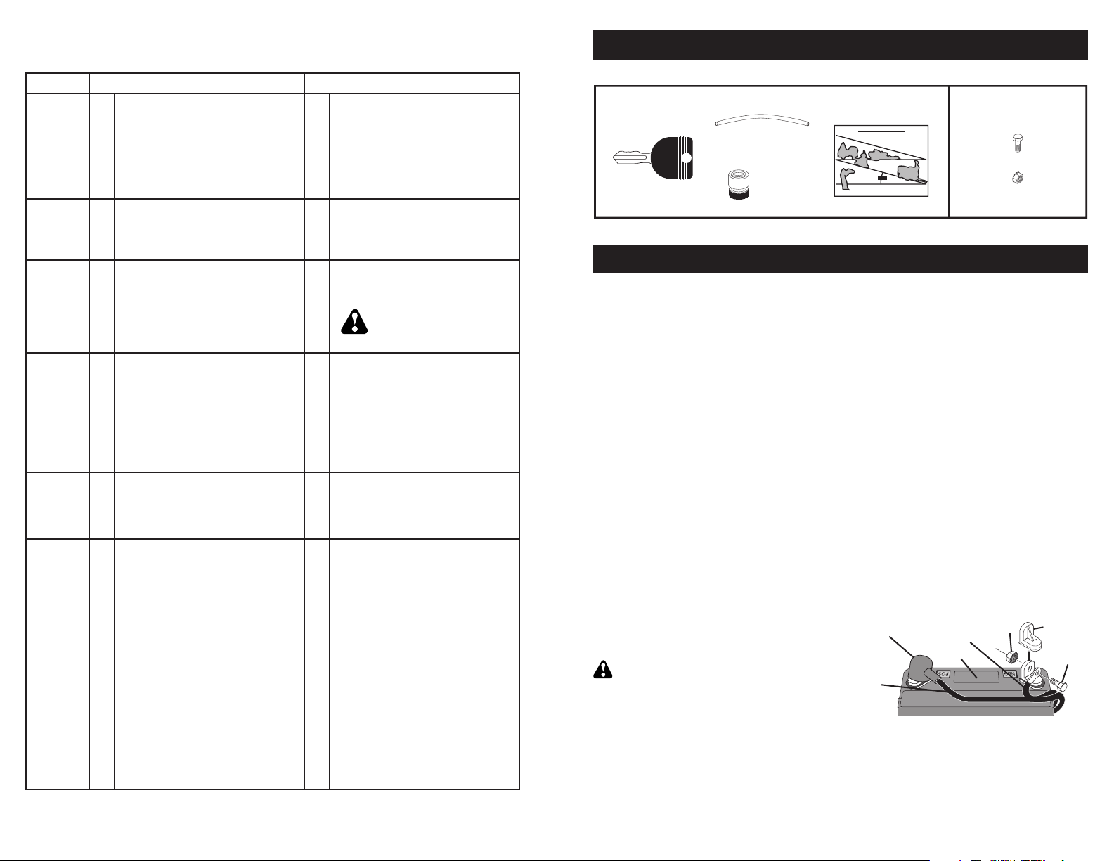
IGNITION
SWITCH
CLUTCH/
BRAKE PEDAL
PARKING
BRAKE
FREE WHEEL
(Automatic Models only)
DANGER, KEEP
HANDS AND
FEET AWAY
ATTACHMENT
CLUTCH
ENGAGED
ATTACHMENT
CLUTCH
DISENGAGED
Failure to follow instructions
could result in serious injury or
death. The safety alert symbol
is used to identify safety inform-
ation about hazards which can
result in death, serious injury
and/or property damage.
DANGER indicates a hazard which, if not avoided,
will result in death or serious injury.
WARNING indicates a hazard which, if not avoided,
could result in death or serious injury.
CAUTION indicates a hazard which, if not avoided,
might result in minor or moderate injury.
CAUTION when used without the alert symbol,
indicates a situation that could result in damage
to the tractor and/or engine.
FIRE indicates a hazard which, if not avoided,
could result in death, serious injury and/or
property damage.
HOT SURFACES indicates a hazard which,
if not avoided, could result in death, serious
injury and/or property damage.
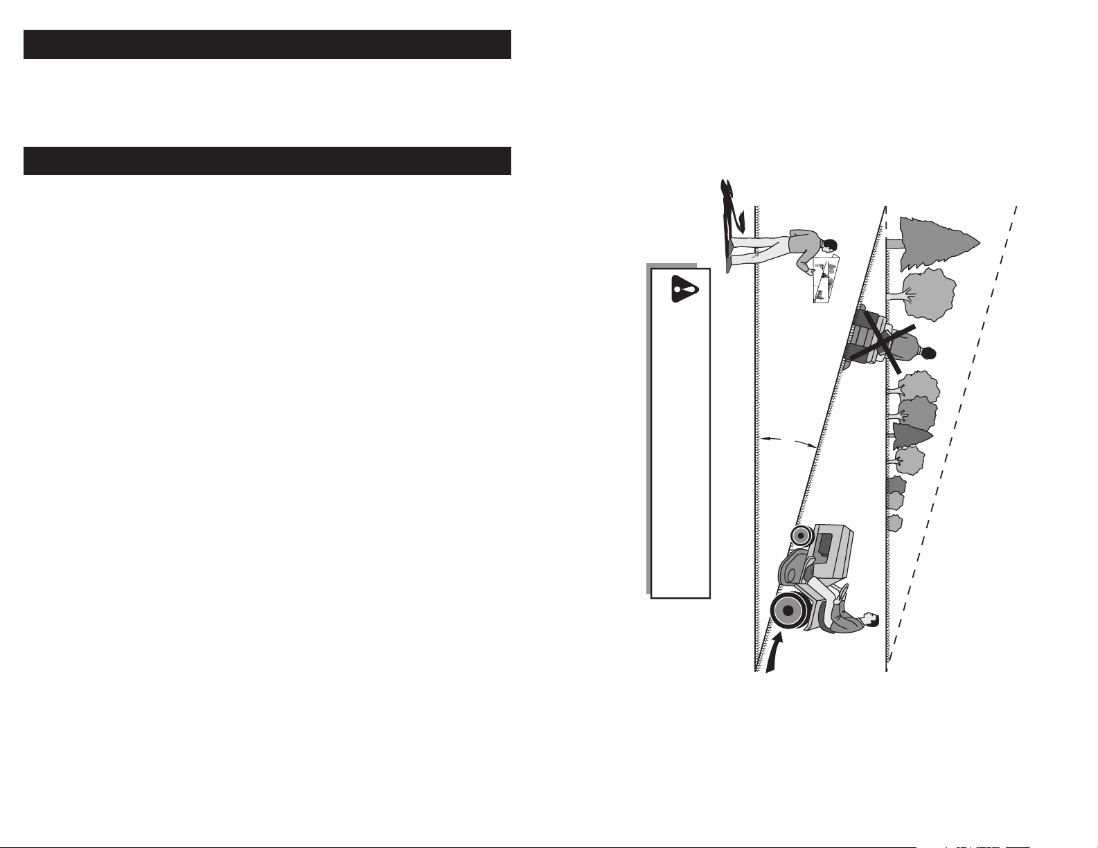
KEEP AREA CLEAR SLOPE HAZARDS
15
15
(SEE SAFETY RULES SECTION)
DIFFERENTIAL
LOCK
REVERSE FORWARD FUEL BATTERYREVERSE
OPERATION
SYSTEM (ROS)
LIGHTS ONCRUISE CONTROL EAR
PROTECTION
RECOMMENDED