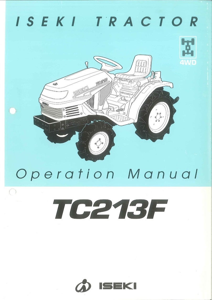
Iseki TG5390 User manual

TG5390
TG5470
(HST ASSIST SYSTEM)
MODELS:
ISEKI TRACTORS

ISEKI TRACTORS
1
TO OUR CUSTOMER
Thank you very much for purchasing an ISEKI tractor.
This operator's manual provides the information necessary for the operation of ISEKI
TG tractor which has the HST assist system. Please refer to the operation's manual of
standard HST models for ordinary operating and maintenance instructions of tractor.
The contents are mainly composed of the following item:
Technical instructions : Essential Items which you should observe while
operating the tractor
Before starting to operate the machine for the first time, you should read this operation
manual and standard HST model's manual thoroughly and carefully until you are
sufficiently familiar with the operation of the machine to do jobs safely and properly. The
manual should be kept in a handy place so you can refer to it when required. You are
advised to refer to it from time to time to refresh your understanding of the machine.
Your dealer has performed the pre-delivery service on your new machine.
He will discuss with you the operating and maintenance instructions given in this manual,
and instruct you in the proper and varied applications of this machine. Call on him at any
time when you have a question, or need equipment related to the use of your machine.
Paragraphs in the manual and labels on the machine which are
accompanied by a caution particularly important information about
safe operation to avoid accidents. You should always keep precautions
in mind and follow them during operation.
Be sure to wear
personnel protective equipment
during operation
In some of the illustrations used in this operation manual, panels or
guards may have been removed for clarity. Never operate the tractor
with these panels and guards removed.
If the removal of a shield is necessary to make a repair, it must be
replaced before operation.
All information, illustrations, and specifications contained in this manual are based on
the latest information available at the time of publication. The right is reserved to make
changes at any time without notice.

TG5390,5470
2
TABLE OF CONTENTS
TO OUR CUSTOMER................................................................................................................................................ 1
TABLE OF CONTENTS............................................................................................................................................. 2
1. INSTRUMENTS & CONTROLS - HST TYPE -...................................................................................................... 3
HST type ............................................................................................................................................................. 3
INSTRUMENT PANEL........................................................................................................................................ 4
Electric Fuel Shut-Off..................................................................................................................................... 4
Main Switch.................................................................................................................................................... 4
Indicator Light Strip........................................................................................................................................ 5
Coolant Temperature Gauge.......................................................................................................................... 6
Tachometer.................................................................................................................................................... 6
Fuel Gauge.................................................................................................................................................... 7
Horn / Light Turn Switch ................................................................................................................................ 7
BRAKES.............................................................................................................................................................. 8
Brake Pedals & Parking Brakes..................................................................................................................... 8
Parking Brake lever........................................................................................................................................ 8
ENGINE SPEED CONTROLS ............................................................................................................................ 9
TRANSMISSION SHIFT LEVERAND CONTROLS (HST type)......................................................................... 10
DIFFERENTIAL LOCK PEDAL........................................................................................................................... 11
FOUR-WHEEL DRIVE SHIFT LEVER................................................................................................................ 11
2. LUBRICATION & PERIODIC MAINTENANCE ..................................................................................................... 12
3. TROUBLESHOOTING........................................................................................................................................... 13
HSTASSIST SYSTEM ....................................................................................................................................... 13
4. SPECIFICATIONS.................................................................................................................................................. 14
ENGINE............................................................................................................................................................... 14
TRANSMISSION-HST TYPE.............................................................................................................................. 14
POWER TAKE OFF (PTO).................................................................................................................................. 14
HYDRAULIC SYSTEM - HST TYPE................................................................................................................... 14
ELECTRICAL SYSTEM ...................................................................................................................................... 15
CAPACITIES....................................................................................................................................................... 15
TREAD WIDTH SETTING
REAR ROPS TYPE............................................................................................................................................. 15
CHECK LIST....................................................................................................................................................... 16
INSTRUMENTS & CONTROLS
3
FIG. 1-1
13
6
8
9
12
11
15
16
13
7
10
2
18
4
14
17
5
INSTRUMENTS & CONTROLS
- HST TYPE -
FIG. 1-1: General layout and location of controls within operator’s area on Tractor. Specific use of these controls is
given later in this section and also in “Operation” section of this book:
1. Steering Wheel
2. Parking Brake Lever
3. Instrument Panel
4. Range Shift Lever
5. Rear PTO Selector Lever
6. Hand Throttle Lever
7. Steering Column Tilt Pedal
8. Brake Pedal
9. Hydro Forward Reverse Pedal
10. Differential Lock Pedal
11. Three Point Hitch Position Control Lever
12. Joystick Control Lever
13. Operator’s Seat
14. Four Wheel Drive (4-WD) Shift Lever
15. External Auxiliary Hydraulics Lever (Option)
16. External Auxiliary Hydraulics Lever (Option)
17. Mid-PTO Selector Lever (Option)
18. Cruise Control Lever
CAUTION: Become familiar with all operat-
ing controls prior to operating Tractor. Read
this book in its entirety before starting.
HST type

TG5390,5470
4
INSTRUMENT PANEL
FIG. 1-2: Arrangement of gauges. Control switches and
indicators located in instrument panel. Items are detailed
in the descriptions that follow:
Electric Fuel Shut-Off
Turn the main switch to off position so as to stop engine.
Main Switch
FIG. 1-3: Main switch, 1, has the four following positions:
・pOFF - Tractor engine and all electrical circuits off.
(except for head light, turn/hazard position light,
tail light, working lamp) Key can be removed.
・OON - Power supplied to all circuits. Normal op-
erating position. Linkage on fuel injection pump
moves (electrically) to the run position.
・GGLOW - Energizes glow plugs to pre-heat com-
bustion chambers and assist starting.
・fSTART - Starter activated. This position spring
loaded to “ON”.
NOTE: Main switch must be turned to “ON” before any
circuits will operate. PTO switch must be off
and gear shift lever in neutral before engine
can be started.
This tractor is equipped with an electric fuel
shut off. When main switch, 1, is turned to
“start”, “on”, or “glow” position and gear shift
lever is placed in neutral, a solenoid moves the
fuel linkage on injection pump to run position to
start engine. When main switch is turned to “off”,
solenoid moves fuel linkage to off position to
stop engine.
・When you heard the horn sound continu-
ously on starting engine or operating For-
ward or Reverse pedal, please stop the
engine.
・In the case of the horn sound a moment
and stop on starting the engine, the ma-
chine is in a normal condition.
・When you heard the horn sound continu-
ously on traveling, apply the brake and
stop immediately. And cut off the engine.
FIG. 1-2
FIG. 1-3
p

INSTRUMENTS & CONTROLS
5
FIG. 1-4: When main switch, 1, is selected to “GLOW”
position, glow indicator, 2, will illuminate after several
seconds to indicate the engine combustion chambers
are preheated and allow cold engine to be started.
Indicator Light Strip
FIG. 1-5: Indicator light strip, 3, contains several warning
lights to monitor certain functions. Currently used posi-
tions (from left to right) are:
・lMain (High) Beam - Illuminates when headlamps
in front grille are selected to high beam position
by light switch.
・MPower Take-Off (PTO) - Illuminates when PTO
control switch is moved to engage PTO clutch
pack (PTO operating). Light will go out when PTO
switch is moved to off.
・oEngine Oil Pressure - Illuminates if engine oil
pressure is low. If light comes on while engine is
running, shut off engine immediately and investi-
gate cause.
・bBattery Charge - Illuminates when main switch is
turned “ON” and will go out after engine starts, to
indicate battery is being charged.
・Coolant Temperature - Illuminates when engine is
overheating. Reduce engine speed to idle, allow
to run at no load sevral minutes and investigate
cause( refer to “Troubleshooting”).
・Fuel - Illuminates when fuel is low level in the fuel
tank.
・Inspection - Illuminates when hourmeter indicates
50/100/200/300/400・・・hour, please inspect
your tractor.
・Caution - Illuminates when it is not normal with
starting engine or sensor of Power shift is not
normal.
・Parking Brake - Illuminates when parking brake
lever is pulled up.
・4WD - Illuminates when 4WD is engaged by shift-
ing 4WD lever.
・† Trailer Indicator - Blink when turn switch is ON
with connecting 7 pins socket to your trailer or
when hazard light switch is ON.
FIG. 1-4
2
FIG. 1-5
3

TG5390,5470
6
Coolant Temperature Gauge
FIG. 1-6: Gauge, 4, indicates engine coolant tempera-
ture when main switch is selected to ON
・- Shows too cool temperature for severe work. Al-
low to warm before applying heavy load.
・- Indicates overheating. Reduce engine speed to
idle, allow to run at no load several minutes and
investigate cause (refer to “Troubleshooting”).
CAUTION: Do not service hot engine. Allow
to completely cool before servicing or re-
moving radiator cap.
Tachometer
FIG.1-7 & 1-8: Scale,5, indicates engine speed in crank
shaft revolutions per minute(rpm). Digital panel indicates
not only engine revolutions but also traveling speed, rear
PTO speed, mid PTO speed, hourmeter, trip meter.
Indication of digital panel is changed by pushing select-
able switch,6.
When rear PTO speed is 540, engine revolutions is ap-
proximately 2430 rpm.
Normally, the PTO speed should be between 540 and
600. Operating the PTO at a speed above 600 is too
fast, and may result in breakdown of the tractor or imple-
ment.
Hourmeter is used to assist in maintenance intervals of
tractor. The extreme right digit indicates 1 hour incre-
ments.
Tripmeter is used to assist in your operation. The ex-
treme right digit indicates 1/10 hour increments.
FIG. 1-6
4
FIG. 1-7
5
FIG. 1-8
6

INSTRUMENTS & CONTROLS
7
Fuel Gauge
FIG. 1-9: Scale, 7, indicates level of diesel fuel in fuel
tank when main switch is “ON”
NOTE: Use only clean diesel fuel and clean area to pre
vent dirt/water entry into fuel tank when refill-
ing.DO NOT run out of fuel as bleeding air from
the system will be required. Keep fuel tank full
to minimize condensation.
CAUTION: DO NOT refill fuel tank with en-
gine running or hot. Allow cooling period.
DO NOT smoke near fuel tank. Clean up any
spilled fuel.
Horn / Light Turn Switch
FIG. 1-10: Horn / Light Turn Switch.
Horn Switch, 8 - Horn will sound when center switch
button is depressed.
Light Switch, 9 - Is a rotary switch with three operating
positions:
・OFF - Fully counterclockwise. All lights off.
・1st - Low beam headlamps and rear tail lights.
・2nd - Main (high) beam headlamps and rear tail lights.
NOTE: When high beam is selected (2nd position),
light in indicator light strip will come on.
Turn Switch, 10 - Operate switch handle in direction
Tractor is being turned. The appropriate flashing amber
warning light (ROPS-mounted) will operate as turn sig-
nal. Return switch to center position to cancel.
NOTE: Turn lights will not self-cancel. Select turn/haz-
ard light switch to center position after complet-
ing turn.
FIG. 1-11: Turn the position lamp switch, 11, to turn the
position lamps on.
Hazard Light Switch, - Press switch, 12, to turn on haz-
ard lights. Both flashing amber warning lights will oper-
ate at the same time.
CAUTION: Hazard lights must be used any
time Tractor is driven on public roadway.
Consult local agencies for other marking re-
quirements.
FIG. 1-9
7
FIG. 1-10
10
8
9
FIG. 1-11
12 11

TG5390,5470
8
FIG. 1-12: Turn/hazard indicator lights, 13 and 14, will
operate with ROPS-mounted warning lights. This pro-
vides operator with easy indication of warning light se-
lection.
BRAKES
Brake Pedals & Parking Brakes
FIG. 1-13: Inner brake pedal, 1, and outer brake pedal, 2,
independently control the respective left and right wheel
brakes, to assist in turning.
During Tractor transport or high speed operation, brake
pedals must be latched together using interlocking plate,
3.
CAUTION: Do not use individual wheel
brakes for transporting or operating at high
speed. Always latch pedals together using
interlocking, plate, 3. Make sure brakes are
adjusted evenly.
Parking Brake lever
WARNING: ALWAYS apply the parking brake
before dismounting from the tractor.
FIG. 1-14 & 1-15: The parking brake acts on the tractor
rear wheels. To engage the brake, pull upward on the
parking brake lever, 4 to lock brakes in applied position.
To release the parking brake, press the button on the
end of the lever and push the lever down.
When pulling upward on the parking brake lever, the
parking brake indicator light will illuminate.
Ensure the parking brake is fully released before driving
off.
FIG. 1-12
13 14
FIG. 1-13
12
3
FIG. 1-14
4
FIG. 1-15

INSTRUMENTS & CONTROLS
9
ENGINE SPEED CONTROLS
CAUTION: Always select engine speed to
ensure safe operation. Reduce speed prior
to turning or reversing Tractor.
IMPORTANT: DO NOT “race” or excessively load cold
engine.
FIG. 1-16: Hand Throttle Lever, 1 - Controls engine
speed and will remain in position selected by the opera-
tor. With hand lever forward, engine will idle. Engine
speed increases as lever is pulled progressively back-
ward. FIG. 1-16
1

TG5390,5470
10
TRANSMISSION SHIFT LEVER AND CONTROLS
(HST type)
One shift lever is used to select a range of ground travel
speed through different gear reductions within the drive
train. A hydrostatic control unit (using a control pedal)
allows infinitely variable speeds, from zero to top speed,
in each range.
FIG. 1-17: Range Shift Lever, 1. Located to the left of
the operator’s seat, range lever provides three major
speed changes.
IMPORTANT: Tractor must be completely stopped
when shifting.
Hydrostatic Control Pedal, 2. Located on the right side
of the platform and it actuates the hydrostatic unit in for-
ward or reverse travel direction.
Depressing the forward portion of the pedal moves
Tractor forward, depressing the backward portion of
the pedal moves Tractor reverse. As each movement is
progressively depressed, a corresponding increase in
ground speed of Tractor will be noticed in the appropri-
ate direction.
Returning pedal towards spring-loaded neutral posi-
tion, will slow Tractor and stop it when neutral position
is reached. When pedal is completely released, Tractor
should remain stopped with the pedal assembly in neu-
tral position.
CAUTION: When you heard the horn sound
continuously on traveling, apply the brake
and stop immediately and cut off the engine.
Cruise Control Lever, 3. Located on the left side the
steering wheel. This lever actuates hydrostatic control
unit for forward travel only. Move forward pedal down
until desired forward speed is achieved, then move
cruise control lever backward to hold this speed. Move
lever forward to slow down and stop.To release cruise
control lever, move lever forward or depress brake ped-
als latched together with interlock plate.
WARNING: Cruise control should only be
used in open spaces, without obstacles,
with unobstructed view or traveling on load.
Before using cruise control lever, be make
sure to set brake pedals to be latched to-
gether with interlocking plate.
If one brake is depressed to release cruise
control,
cruise control would not be released.
You should be thoroughly familiar with releasing cruise
control. See operation section.
NOTE: Do not move cruise control lever without first mov-
ing the Hydrostatic control pedal downward in the
forward position, to prevent mechanical failures.
Do not use cruise control lever in reverse direction.
FIG. 1-17
1
32
FIG. 1-19
PEDAL
FIG. 1-18
3UNLOCK
LOCK

INSTRUMENTS & CONTROLS
11
DIFFERENTIAL LOCK PEDAL
FIG. 1-20: When differential lock pedal, 1, is depressed,
both rear axles are locked together to provide equal
traction to both rear wheels. This is especially important
when operating in loose soil or slippery conditions.
Disengage differential lock, by releasing foot pedal. If
lock does not immediately disengage, tap right and left
brake pedals alternatively until pedal is released.
CAUTION: When differential lock is en-
gaged, steering ability of Tractor will be
greatly reduced. Disengage before attempt-
ing a turn. Do not use during transport.
FOUR-WHEEL DRIVE SHIFT LEVER
FIG. 1-21: Shift lever, 1, engages and disengages drive
for the front axle. Lever forward, the front axle (4-WD) is
disengaged. Lever backward, the front axle is engaged,
and power is available to both front and rear axle.
When shift lever is pulled backward, the 4-WD indicator
light will illuminate.
IMPORTANT: Make sure the tractor is completely
stopped before engaging or disengaging
four-wheel drive.
Do not use 4-WD on hard surface. Rapid
wear of front tires and possible drive line
damage could occur if 4-WD is operated
for prolonged periods on hard surface.
FIG. 1-20
HST type
FIG. 1-21
1
FIG. 1-22

TG5390,5470
12
LUBRICATION & PERIODIC MAINTENANCE
Fuse Location (HST Assist type)
Main Fuse Box, A- Located on right side, to steering
post.
Ref Amp Function
1 15A Turn Lights
2 20A Head Lights, Tail Lights, Position
Light, Horn
3 10A Stop Light
4 10A Instrument Panel
5 15A Alternator, Fuel Pump, Safety Relay
6 10A ECU and Control System
7 20A Cab Power Supply
8 15A Assistant Power
9 15A Assistant Power
10 20A Work Light
11 10A Head Light-Hi beam(Right)
12 10A Head Light-Hi beam(Left)
13 10A Head Light-Low beam(Right)
14 10A Head Light-Low beam(Left)
15 5A Tail Light(Right)
16 5A Tail Light(Left)
17 5A Position Light(Right)
18 5A Position Light(Left)
19 5A License Plate Light
20 5A Check Mode Fuse
・Slow-Blow Fuses, B & C- In-line fuses protect rele-
vant circuit by melting when sustained heavy electrical
load or short circuit is encountered.
Fuse B is located above and to the left of battery.
Fuse C is located on left side, to rear of engine.(above
the starter)
Ref. Amp Function
B-1 40A Engine Stop Solenoid (Green)
B-2 50A Main circuit
(Red)
C-1 60A Alternator circuit
(Yellow)
C-2 40A Cabin circuit (Green)
NOTE: Failure of fuse, C,is usually caused from incor-
rect polarity (such as reversed cables when us-
ing a booster battery). Failed fuse will not allow
battery to be charged during normal operation.
IMPORTANT: Fuses are of specific amperage capacity
for the circuit in which they are located.
Do not replace fuses with unauthorized
parts.
D: Assistant Power 120W×2
E: Assistant Power 70W (with key switch ON)
F: Work Light 100W×2
G: 7Pins Socket
H: Seat Switch
G: 7 Pins Socket Location
Ref. DIN Function
①L Left Turn
②52 -
③31 Ground
④R Right Turn
⑤58R Tail Light
⑥54 Stop Light
⑦58L Tail Light
FIG. 2-1

TROUBLESHOOTING
13
TROUBLESHOOTING
Please refer to the troubleshooting of standard models for the other problems.
HST ASSIST SYSTEM
Problem Possible Cause Remedy
Sound of horn does not stop
when starting engine. Blown fuse
Defective controller
Defective hydraulic system
Defective wiring or sensors
Stop the engine.
Consult your dealer.
Sound of horn does not stop
when tractor traveling. Blown fuse
Defective controller
Defective hydraulic system
Defective wiring or sensors
Depress brake pedal and
slow down to stop the engine.
Consult your dealer.
Horn sounds a moment
when starting engine. The engine was stopped when
the cylinder is activated. When horn stop, machine is normal.
Tractor does not move to
forward or reverse. Range shift lever is “Neutral” Shift the Range shift lever
to the position except “Neutral”.
Blown fuse
Defective controller
Defective hydraulic system
Defective wiring or sensors
Stop the engine.
Consult your dealer.

TG5390,5470
14
SPECIFICATIONS
ENGINE TG5390 TG5470
Make Iseki..................................................................Iseki Diesel ............................................................Iseki Diesel
Model ..............................................................................E3CDT.....................................................................E4CG
Type of Injection, ...................................................... Indirect Injection ....................................................Indirect Injection
.......................................................................Overhead Valve......................................................Overhead Valve
Aspiration.................................................................... Turbo charger ..............................................................Natural
Displacement..................................................................1498 cm3................................................................2197 cm3
Number of Cylinders..............................................................3..............................................................................4
Bore ..............................................................................87 mm ...................................................................87 mm
Stroke ..............................................................................84 mm ..................................................................92.4 mm
Engine Horsepower (Net).....................................27.9kw @ 2600 min-1............................................33.8kw @ 2600 min-1
PTO Horsepower (Estimate)
Stanadard and Power shift type ........................23.0kw @ 578 PTO min-1...................................... 27.9kw@ 578 PTO min-1
HST type............................................................23.0kw @ 578 PTO min-1...................................... 27.9kw@ 578 PTO min-1
Firing Order ....................................................................... 1-3-2 .....................................................................1-3-4-2
Compression Ratio..........................................................21.7±0.5..................................................................21.8±0.5
Low Idle Speed..........................................................980-1020 min-1.....................................................1010-1050 min-1
High Idle Speed........................................................2760-2860 min-1....................................................2810-2910 min-1
Valve Clearance (Cold);Intake.........................................0.25 mm..................................................................0.35 mm
Air Cleaner....................................................................Dry element............................................................Dry element
Engine Cooling...................................................Liquid, forced circulation........................................Liquid, forced circulation
Cold Starting Aid.........................................................Glow plugs (3)........................................................Glow plugs (4)
TRANSMISSION-HST TYPE
Type: Primary ..................................................................stepless..................................................................stepless
Range........................................................3-speed sliding mesh............................................. 3-speed sliding mesh
Gear Speeds .....................................................3 gears forward, 3 reverse......................................3 gears forward, 3 reverse
Clutch ...............................................................................None ......................................................................None
POWER TAKE OFF (PTO)
Type ..............................................................Independent, engine driven....................................Independent, engine driven
Control.................................................................Electrohydraulic control..........................................Electrohydraulic control
Clutch .....................................................
Hydraulically engaged, multi-plate wet disc....................Hydraulically engaged, multi-plate wet disc
Rear PTO Shaft................................................35 mm diameter, six spline ....................................35 mm diameter, six spline
Output..........................................................Clockwise rotation..................................................Clockwise rotation
Engine Speed @ 540 PTO rpm ....................2430min-1..............................................................2430min-1
@ 1000 PTO rpm..................2500min-1..............................................................2500min-1
Mid-PTO Shaft (Option) ..............................25.4 mm diameter, fifteen spline................................35 mm diameter, six spline
Output..........................................................Clockwise rotation..................................................Clockwise rotation
Mid-PTO Speed @ engine rpm..................1916 @ 2600 min-1................................................1916 @ 2600 min-1
HYDRAULIC SYSTEM - HST TYPE TG5390 TG5470
Steering System
Type...................................................................Hydrostatic..............................................................Hydrostatic
Pump............................................Separate engine-mounted gear pump....................Separate engine-mounted gear pump
Maximum Output.............................................18.5 litre/min..........................................................18.5 litre/min
Pressure............................................. Relief valve setting 6860 kPa ............................... Relief valve setting 11767 kPa
Main Hydraulic System; Pump ............................Engine-mounted pump .......................................... Engine-mounted pump
Maximum Output.............................................34.4 litre/min..........................................................43.8 litre/min
Pressure............................................ Relief valve setting 15695 kPa ..............................Relief valve setting 15695 kPa
Rear Linkage
Type..............................................................Three-point hitch....................................................Three-point hitch
Size....................................................................Category I ..............................................................Category I
Control...........................................
Operated by single position control lever........................Operated by single position control lever
Lift Capacity measured at ball ends.............1270 kg .................................................................1580 kg
measured at 24 inches.............970 kg ..................................................................1400 kg

SPECIFICATIONS
15
ELECTRICAL SYSTEM
System Voltage ..................................12 volt, negative (-) ground....................................12 volt, negative (-) ground
Battery cca @
18 degreesC (0 degreesF)
.......630 cca (80D26R).................................................710 cca (115D31R)
Charging
Except CABIN type.....................
40 amp alternator with internal regulator / rectifier .....................40amp alternator with internal regulator / rectifier
CABIN TYPE..............................
40 amp alternator with internal regulator / rectifier .....................60amp alternator with internal regulator / rectifier
CAPACITIES
Engine Crankcase with Filter...........................................4.7 litres .................................................................8.0 litres
Transmission ..................................................................31.0 litres ...............................................................38.0 litres
Fuel Tank........................................................................40.0 litres ...............................................................50.0 litres
Cooling system................................................................6.7 litres .................................................................7.6 litres
Front Drive Axle (4WD Only)...........................................7.5 litres .................................................................8.5 litres
TREAD WIDTH SETTING 5390 TG5470
REAR ROPS TYPE
tyre type location size Setting(mm) tyre type locationsize Setting(mm)
Front tyres .................................. AG 7-16 ..........................................1090.................AG 9.5-16..............................................1220
AG 8-16 ..........................................1150........... Turf 29x12.00-15 ........................................1215
Turf 212/80D-15....................................1135
tyre type location size Ret. Setting(mm) tyre type location size Ref. Setting(mm)
Rear tyres.................................AG 12.4-24..................1....................1100................ AG 13.6-28 ....................1....................... 1140
............................2....................1175........................................................2.......................1220
............................3....................1215........................................................3.......................1340
............................4....................1300........................................................4.......................1420
............................5....................1415........................................................5.......................1540
AG 13.6-24 ..................1....................1100
............................2....................1175
............................3....................1215
............................4....................1300
............................5....................1415
Turf 355/80D-20....................................1170............Turf 475/65D-20.........................................1430

TG5390,5470
16
FACTORY RECOMENDED
NEW TRACTOR PRE-DELIVERY INSPECTION CHECK LIST
ISEKI
USER'S NAME AREA DATE
DEALER ADDRESS
TRACTOR MODEL SERIAL NO.
ENGINE SERIAL NO. COUNTRY
THIS PRE-DELIVERY INSPECTION CHECK LIST IS PROVIDED TO IDENTIFY THE CHECKED AND NECESSARY
ADJUST BY THE DEALER PRIOR TO DELIVERY OF THIS MACHINE.
Inpsected the following and adjusted if necessary.
ENGINE
□Radiator filled with solution □Engine RPM (full throttle)
□Cooling system connections □Governor performance
□Fan and alternator belt tension □Electrical connections
□Engine oil □Service air cleaner
□All oil drain plugs □All cleaner connections
□Oil pressure □Fuel line connections
□Engine RPM (idle) □Injection pump oil
CHASSIS
□Tyre inflation □Hydraulic system performance
□Front wheel hub bolts □Drive test
□Rear wheel hub bolts □Lubricate all grease fittings
□Torque all chassis bolts □Power-assisted streering operation (if equipped)
□Transmission oil □Front axele oil (4-WD)
□Front reduction case □Front axele operation (4-WD)
□Break pedal free-play □Operation manual with tractor
□Clutch pedal free-play
Explained the following to the owner.
□Operation manual □Fuel system servicing and cleanliness
□Safety and safety start system □Draining of engine and radiator
□Instruments and controls □Air cleaner service
□Breaking in the new tractor □Tyre care
□Power take-off operation □Wheel tread adjustment
□Lubrication and maintenance schedule □Storage
□Explain use of Rollover Protective Structure (ROPS)

WIRING HARNESS CABLE
17
TG5390FH-3, TG5470FH-3 (SHEET A)
WIRING HARNESS CABLE

18
TG5390,5470
TG5390FH-3, TG5470FH-3 (SHEET B)

Overseas Business Division
3-14, Nishi-Nippori, 5-chome, Arakawa-ku,
Tokyo 116-8541, Japan
Phone: (03) 5604-7658
Fax: (03) 5604-7703
OM-TG5390H3/-EN-10
0807-01-10
Printed in Japan
TG5390
TG5470
This manual suits for next models
1
Table of contents
Other Iseki Tractor manuals
Popular Tractor manuals by other brands

NMC-WOLLARD
NMC-WOLLARD 140 Operation, maintenance and parts manual

TYM
TYM 3515C manual

Simplicity
Simplicity 9518 Series Operator's manual

Cub Cadet
Cub Cadet 2166 Operator's manual

AL-KO
AL-KO Solo T22-103.9 HD-A V2 Translation of the original installation instructions

Cub Cadet
Cub Cadet GT 2186 Operator's manual