manuals.online logo
Brands
  1. Home
  2. •
  3. Brands
  4. •
  5. Craftsman
  6. •
  7. Water Pump
  8. •
  9. Craftsman 390.306062 User manual

Craftsman 390.306062 User manual

SEARS
OWNER'S
MANUAL
ModelNo.
390.306062
CAUTION:
Read and Follow
All Safety Rulesand
Operating Instructions
BeforeFirstUse of
ThisProduct.
SaveThisManualFor
FutureReference.
I:RRFTSMRN°
BATTERY OPERATED
BACKUP SUMP PUMP
•Safety Instructions
• Operation
• Installation
• Troubleshooting
• Repair Parts
Sears, Roebuck and Co., Hoffman Estates, IL60179 U.S.A.
PRINTED IN U.S.A. Form No. F642-9510 (Rev. 11/4/98)
CONTENTS •
Introduction/Warranty ...................... :................................. 2
Safety ................................................................................... 2
Performance ........................................................................ 3
Charger Operation ............................................................... 3
Battery Requirements .......................................................... 4
Installation/Operation ...................................................... 4-5
Electrical ........................................................................... 5-6
Service/Troubleshooting .................................................. 6-7
Repair Parts .......................................................................... 7
INTRODUCTION
Please take a few minutes to read ourinstrnctions before irv
stalling your Backup Sump Pump. It will help to assure per-
fect installation and help you avoid needless service
expenses.
IMPORTANT SAFETY INSTRUC-
TIONS for BATTERY CHARGER
I"IL,_WARNINGIRisk of electrical shock, fire, or explo-
sion. Read all instructions in owner's manual and on
charger, pump, and battery before using battery charger.
1. Unplug battery charger before attempting any cleaning.
Turning offcontrols does not reduce the risk of electrical
shock.
2. Charge only rechargeable 12-volt lead-acid batteries.
Other types may burst when charged with this charger.
3. Do not let charger get wet.
4. Use only attachments recommended or sold by battery
charger manufacturer.
5. When unplugging charger, grasp plug (not cord) to avoid
risk of damage to cord or plug.
6. Locate cord so that it cannot be stepped on, tripped over,
damaged, stretched, or flooded.
7. Do not modify cord or plug.
8. Do not attempt to service charger; it has no user-ser-
viceable parts. If charger is dropped, struck, or otherwise
damaged, take it to a qualified service technician.
SAVE THESE INSTRUCTIONS
RULES FOR SAFE INSTALLATION AND OPERATION
Carefully read and follow all safety instructions in this
n_ariual or on pump.
_k This is the safety alert symbol. When you see this
symbol on your pump or in this manual, look for 9ne of the
following signal words and be alert to the p6tendal for per-
sonal injury!
_ DANGER warns about hazards that will cause
serious personal injury, death or major property damage if
ignored.
IAWARNING}wARN]NG warns about hazards that can
cause serious personal injury, death or major property dam-
age if ignored.
& ]CAUTION warns about hazards that will or
1
CAUTION
can cause minor personal injury or property damage if ig-
nored.
The word NOTICE indicates special instru_iolas which are
important but not related to hazards.
1.To avoid risk of serious bodily injury and property dam-
age, read safety instructions carefully before installing
pump.
2.Follow local and/or national plumbing and electrical
codes when installing pump. A ground fault circuit inter-
rupter (GFCI) is recommended for use on any electrical
appliance submerged in water.
2
3.Use this pump only for backup sump pump duty in a res-
idential appfication. Ris not designed as a primary sump
pump.
4, [AWAaNING_][_azardous Voltage. Can cause severe or
fatal electrical shock. Do not plug in or unplug battery
charger while standing on a wet floor or in water. Be sure
one hand is free when plugging in or unplugging charger.
If basement floor is wet, disconnect power to basement
before walking on floor.
5.Do not lift pump by electrical cord.
6. Pump water only with this pump.
7.Do not run pump dry. To do so will damage seals and can
cause leaking and property damage.
8. Pump is permanently lubricated at the factory. Do not try
to lubricate it!
9. Keep battery charger and battery box in a dry, cool, well
ventilated area.
10.To avoid danger of fire or explosion, keep sparks and
flame away from battery.
11. L&WARNING_ Battery acid is corrosive. Do not spill on
skin, clothing, or battery charger. Wear eye protection
when working on battery.
12.Maximum vertical pumping distance is 15 feet.
13. Make sure sump is clear of debris.
BASIC TOOLS AND MATERIALS NEEDED
Pipe Wrenches Screwdriver
Hacksaw 1-1/4" Check Valve
Adjustable Wrench Teflon Tape
Knife 12-volt Battery
GENERAL INFORMATION
The Battery-Powered Back-up Sump Pump is not a substitute
for your primary sump pump. It is designed as a backup
pump to pinch-hit for your primary sump pump during a
power outage or other problem which prevents normal op-
eration. Do not use it to pump flammable liquids or chemi-
cals.
Keep battery charger dry and protected from damage.
In an emergency (such as an extended power outage)
which depletes the system battery, your automobile battery
may be temporarily substituted. Be sure to replace the sys-
tem battery as soon as possible.
CHARGER OPERATION
Backup pump vdll start automatically when sump water
level rises far enough to trip float switch. After a delay of
about 4 seconds, alarm will sound. Silence alarm by pushing
ALARM TEST/RESET button. In normal (switch actuated) op-
eration, alarm is locked-out until about 4 sec6nds after float
switch has dropped to OFF position; cycle can then begin
again.
Test alarm by pushing ALARM TEST/RESET button when
alarm is not sounding. Alarm will then sound as long as but-
ton is held down. Pushing ALARM TEST/RESET button to
test alarm overrides lockout, so alarm can be tested at any
time.
If alarm sounds, check operation of primary pump, which
may need service. If battery backup operation is due to a
power outage, alarm will sound, but no service is likely to
be required to primary pump.
Battery charger has capacity to run pump and charge battery
at the same time as long as power to the charger is not in-
terrupted. If power to charger circuit is interrupted, the
length of time that the backup pump will run depends on
the Ampere-hour capacity of the battery used.
Extended periods of operation (for example, during an ex-
tended power outage) may exhaust the battery. However,
once the load is removed, usually it will self-regenerate far
enough to allow the charger to start. The battery charger will
begin charging the battery as long as the battery has a charge
of at least 1/2 volt, and power is available to the charger.
After power is restored, charger will automatically re<barge
battery fully in about six hours.
NOTICE: Some trouble conditions will cause the alarm to
sound. See chart below for causes and action:
PROBLEM _- ACTION
Back-up pump has run Push 'Reset'. Check main pump.
Power out more than Disconnect charger from battery.
24 hours Call power company.
Continuous charging Disconnect charger from battery.
more than 24 hours Check for defective battery.
Loose connection or Disconnect charger from battery.
no power to charger Check plug, receptacle, and
power at main breaker.
After restoring power or replacing battery, alarm can be
reset.
•Purchase locally.
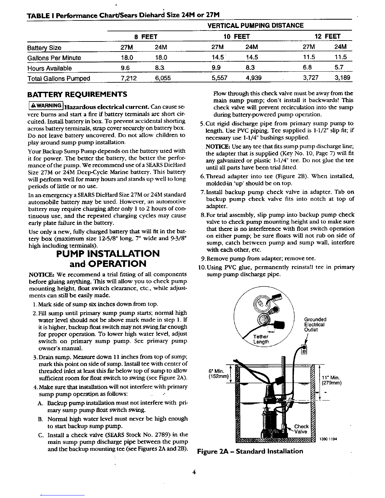
For small/shallow sump pits install as illustrated above. Installation Kit 2785
includes the necessar_ clamps and support pad needed for this installation.
Follow other instructions in the owner's manual.
Figure I - Installation in small or shallow sumps
- use Kit 2785; sump diameter is exaggerated
for clarity.
TABLE I Performance Chart/Sears Diehard Size 24M or 27M
VERTICAL PUMPING DISTANCE
8 FEET 10 FEET 12 FEET
Battery Size 27M 24M 27M 24M 27M 24M
Gallons Per Minute 18.0 18.0 14.5 14.5 11.5 11.5
Hours Available 9.6 8.3- 9.9 8.3 6.8 5.7
Total Gallons Pumped 7,212 6,0_55 5,557 4,939 3,727 3,189
BATTERY REQUIREMENTS
[A WARNING] Hazardous electrical current. Can cause se-
vere burns and start a fire if battery terminals are short cir-
cuited. Install battery in box. To prevent accidental shorting
across battery terminals, strap cover securely on battery box.
Do not leave battery uncovered. Do not allow children to
play around sump pump installation.
Your Backup Sump Pump depends on the battery used with
it for power. The better the battery, the better the perfor-
mance of the pump. We recommend use of a SEARS DieHard
Size 27M or 24M Deep-Cycle Marine battery. This battery
will perform well for many hours and stands up well to long
periods of little or no use.
In an emergency a SEARS DieHard Size 27M or 24M standard
automobile battery may be used. However, an automotive
battery may require charging after only 1to 2 hours of con-
tinuous use, and the repeated charging cycles may cause
early plate failure in the battery.
Use only a new, fully charged battery that will fit in the bat-
tery box (maximum size 12-5/8" long, 7" wide and 9-3/8"
high including terminals).
PUMP INSTALLATION
and OPERATION
NOTICE: We recommend atrial fitting of all components
before gluing anything. This will allow you to check pump
mounting height, float switch clearance, etc., while adjust-
ments can still be easily made.
1. Mark side of sump six inches down from top.
2.Fill scamp until primary sump pump starts; normal high
water level should not be above mark made in step 1. If
it is higher, backup float switch may not swing far enough
for proper operation. To lower high water level, adjust
switch on primary sump pump. See primary pump
owner's manual.
3.Drain sump. Measure down 11 inches from top of sump;
mark this point on side of sump. Install tee with center of
threaded inlet at least this far below top of sump to allow
sufficient room for float switch to swing (see Figure 2A).
4.Make sure that installation will not interfere with primary
sump pump operation as follows:
A. Backup pump installation must not interfere with pri-
mary sump pump float switch swing.
B. Normal high water level must never be high enough
to start backup sump pump.
C. Install a check valve (SEARS Stock No. 2789) in the
main sump pump discharge pipe between the pump
and the backup mounting tee (see Figures 2A and 2B).
How through this check valve must be away from the
main sump pump; don't install it backwards! This
check valve will prevent recirculation into the sump
during battery-powered pump operation.
5.Cut rigid discharge pipe from primary sump pump to
length. Use PVC piping. Tee supplied is 1-1/2" slip fit; if
necessary use 1-1/4" bushings supplied.
NOTICE: Use any tee that fits sump pump discharge line;
the adapter that is supplied (Key No. 10, Page 7) will fit
any galvanized or plastic 1-1/4" tee. Do not glue the tee
until all parts have been trial fitted.
6.Thread adapter into tee (Figure 2B). When installed,
molded-in 'up' should be on top.
7.install backup pump check valve in adapter. Tab on
backup pump check valve fits into notch at top of
adapter.
8.For trial assembly, slip pump into backup pump check
valve to check pump mounting height and to make sure
that there is no interference with float switch operation
on either pump; be sure floats will not rub on side of
sump, catch between pump and sump wall, interfere
with each other, etc.
9. Remove pump from adapter; remove tee.
lO.Using PVC glue, permanently reinstall tee in primary
sump pump discharge pipe.
6" Min. T_
(152mm)1 m
Grounded
Electrical
Outlet
4
__ 1380 1194
Figure 2A - Standard Installation
:
4
_Hazardous fumes. Follow cement manu-
facturer's instructions. Use PVC cement only in a well
ventilated place away from fire or flame.
11.Put clamp on adapter;, leave loose. Mount check valve in
adapter; thread assembly into tee.
12. Slip pump into check valve. Tighten clamp.
1-1/2xl -1/2xl -1/4
Ij Tee - PVC
'{_ Pipe Check
Valve
14640195
_--_1,----- ReducerBushing(2 Supplied)
f---1
._---- Main PumpDischargePipe
,>-__,.,
I _ I"_-- CheckValve toPrevent
i _ i Recirculationinto Sump
/____j
Figure 2B - Installation Diagram
13. Make sure battery is fully charged; then check operation
by disconnecting power to primary sump pump and fill-
ing sump until Backup Sump Pump starts. Run Backup
Pump through one complete cycle.
ELECTRICAL CONNECTIONS
AWARNING JHazardous voltage. Can cause serious or
fatal electrical shock. Review safety instructions, Page 2, be-
fore operating charger.
If your outlet is not grounded, install a copper wire (at least
14 gauge) from the outlet box to a cold water pipe. Use
ground clamp on pipe• BE SURE that the cold water pipe
used has metal continuity to electrical ground. Battery
charger is double insulated. DO NOT modify cord or plug.
CHARGER/BATI'ERY INSTALLATION
NOTICE: Alarm will sound when charger is first connected
to battery. Press ALARM TEST/RESET button on charger. If
alarm continues to sound, disconnect one charger lead from
the battery and reconnect it. Press ALARM TEST/RESET
again; alarm will stop sounding.
1. Connect charger as shown in Figure 3.
A. Connect Positive (+) lead from charger to positive battery
post.
B. Connect Negative (-) lead from charger to negative bat-
tery post.
C. Third lead from charger is factory connected to lead from
pump motor/float gwitch.
NOTICE: If charger is connected backwards, pump will
not operate properly, battery will not charge.
2. Plug in power cord to a115-125 Volt AC outlet delivering
at least 2 amps. Do not use a switch controlled outlet.
Mark circuit in main power panel =Backup sump pump
power supply; do not turn off".
3. With charger properly connected and iplugged in, the
panel on the front of the charger will appear _ in one of
the following:
A. If battery is dead, charger will supply about 10 amps
power (see Figure 4A).
B. If battery is near full charge, charger will deliver about
5 amps power (see Figure 4B).
C. If battery is fully charged, charging current will be 0
amps and green LED lamp will be lighted (see Figure
4C).
Black
Battery Clamp
Positive
Black
t411 1194
Figure 3 - Wiring Connections
A,
B,
CHARGING
Co
1413 1194
Figure 4 - Battery Backup Control Panel
A. Battery depleted - charging current 10amps.
B. Battery nearly charged - current about 5 amps.
C. Charge comlSlete - current 0amps, LED lightsup.
4. The charger is equipped with aiself-resetting circuit
breaker which protects it from teanporary overloads. In
case of an overload, the circuit breaker will open. It au-
tomatically resets after a short cool<lown period. In some
conditions where the overload is extended the breaker
will cycle, repeating the open/reset process Indefinitely.
When this happens, normally the charger will emit a dick-
ing sound as the breaker opens and resets.
NOTICE: If the clicking sound continues for more than
30 minutes or so, check for reversed charger connections
to the battery and for shorted cells in the battery.
BATTERY MAINTENANCE
NOTICE: To protect battery case from chipping and goug-
ing, do not let battery sit on concrete floor. Install battery on
a shelf or protective pad (plywood, 2x4s, etc.). Always in-
stall battery in a dry location that is protected from flooding.
Every three months, check battery as follows to maintain
battery in best condition:
1. Unplug battery charger.
2. On batteries with removable top caps, measure specific
gravity of the electrolyte. Use a hyclrometer (available at
auto parts stores). If the specific gravity of any cell is less
than 1.225 or if there is more than .050 variation between
cells, replace the battery.
3. Check electrolyte level and refill as needed.
4. Check battery terminals and clamps for tightness and cor-
rosion. Clean and tighten as needed.
5. Plug in battery charger.
TROUBLESHOOTING
Pump won't run.
I. Check all connections.
2. Check for low or defective battery.
3. Check that automatic switch is free to swing up and
down.
4. Blown fuse in switch circuit. Unplug pump and check to Figure 5
see ifimpeller is free to turn. Ifimpeller is locked, remove
the housing around the impeller and remove the ob-
struction. Reassemble pump and reconnect. Replace fuse.
Motor hums but pump won't run:
1. Check for low or defective battery.
Pump runs but pumps very tittle or no water:
1. Make sure a check valve is installed and functioning be-
tween primary pump discharge and Backup Sump Pump
tee. Figure 6
2. Check for obstruction in discharge pipe.
3. Discharge pipe length and/or height exceeds capacity of
pump. See Table I, Page 4, for pump capacity.
4. Check for low or defective battery. Figure 7
Pump cycles too frequently: ..
1. Tether length too short on automatic float switch. Make
sure that tether is at least 2"; see Figure 2.
2. Main check valve located between discharge of primary
pump and the Backup Sump Pump tee or check valve not
installed or working properly. Install or repair as required.
SWITCH REPLACEMENT
1. Unplug battery charger from wall outlet.
2. Disconnect both battery daml_s from battery terminals.
3. Unbolt black switch wire from battery clamp.
4. Unplug fuse holder in white wire; save fuse.
5. Make a note of tether length (see Figure 2) before loos-
erring cord clamp.
6. Remove cord from cord clamp and replace with new
cord. Make sure tether length is the same as the old
switch's tether.
7. Strip insulation off of white wire on new switch, leaving
3/8" bare wire'exposed at the wire end (see Figure 5).
8. Insert stripped wire end in small end of fuse holder half;
crimp holder onto wire and check crimp for tightness
(Figure 6).
NOTICE: Be sure that fuse holder half which you are in-
stalling will mate with fuse holder half on pump wire.
9. Insert fuse into holder and snap halves of housing to-
gether (Figure 7).
lO.Remount block on band and cord clamp assembly on
pump.
11. Strip black swifch wire back 3/8" from end of wire. Crimp
wire terminal onto end of wire and check for tightness.
12. Bolt black switch wire onto battery terminal clamp.
13. Reinstall battery clamps:
A. Black switch wire damps to positive battery terminal.
B. Black pump wire clamps to negative battery terminal.
NOTICE: DO NOT reverse terminal connections.
14.Turn pump upside down; unclip and remove screen. Do
not remove screw-mounted bottom plate. Lift switch to
momentarily "bump" pump. Check for correct operation
and rotation (pump must rotate counter-clockwise
when looking at end of shaft - Figure 8). If not, reverse
wires to battery and recheck.
Figure 8
6
15. Replace screen.
16. Plug in charger to wall outlet.
17.Fill sump with water and check switch action. Adjust
tether ff necessary.
LA CAUTION ]DO NOT test run pump for more than
5seconds without water in it. Running pump dry for
extended periods could damage pmnp and voids war-
fancy.
Figure 9 - Battery Hold Down Strap Buckle Threading
Craftsman Battery Backup Sump Pump
Model 390.306062
Brown -.
Black 6A 6B
¥ Clamp
y Clamp
12
/
Negative 14121194
REPAIR PARTS LIST
Key No, Part No. Pert Description
1
2
3
4
5
6A
6B
7
8
9
10
11
12
PS217-5E
PS17-41
CC0030-13
U17-1148
U17-1149
PS17-100
PS117-77A
PS22-1
PS78-3P
U78-846P
U78-876P
Switch Assembly #
Pump Complete'*"
Cord Clamp
Fuse Holder
15-Amp Time-Delay Fuse (2 suppliedt)
Wire Ten,ninal (4 Red.)
BatteryTerminal Clamps (2 Req,)
Battery Case (includes strap and strap brackets)
Charger'*
Check Valve
Hose Clamp 1" min. -2" max. S.S.
Pips Adapter
Tee 1-1/2 x 1-1/2 x 1-1/4 PVC
Reducer Bushing (2 Req.)
# When ordering, alsoorder Key Nos. 4(Fuse Holder) and 5 (Fuse) requiredfor installation.
* Not illustrated.
** Standard Hardware Item; purchase locally.
*** No component pads available for pump or battery charger.
tSecond fuse issuppliedas spare,
7
SEARS
OWNER'S
MANUAL
Model No.
390.306062
The model number Of
your Backup Sump Pump
will be located on the
pump, not the battery
charger
When requesting service
or ordering parts, always
give the following
information:
•ProductType
•Model Number
• Part Number
• Part Description
I:RRFTSMRW
BATTERY OPERATED
BACKUP SUMP PUMP
Fortherepairor replacementpartsyouneed
Cull7 am-7pm, 7daysaweek
1-800-366-PART
(1-800-386-7278)
ForIn-homemajorbrandrepairservice
Call24 hoursaday,7 daysaweek
1.800-4-REPAIR
(1-800-473-7247)
Forthe locationofa
SearsRepairServiceCenterinyourarea
Call24 hoursa day,7 daysaweek
1-800-488-1222
Forinformationonpurchasinga Sears
MaintenanceAgreementortoinquire
aboutanexistingAgreement
callgam- 5 pro,Monday-Saturday
1-800-827-6655
SEARS
A
Amer_a_ RepairSpecialists
Sears, Roebuck and Co., Hoffman Estates, IL 60179 U.S.A.

Other Craftsman Water Pump manuals

Craftsman 390.2532 User manual

Craftsman

Craftsman 390.2532 User manual

Craftsman CMXWUSD61236 User manual

Craftsman

Craftsman CMXWUSD61236 User manual

Craftsman HYDROGLASS 390.2511 User manual

Craftsman

Craftsman HYDROGLASS 390.2511 User manual

Craftsman 390.251183 User manual

Craftsman

Craftsman 390.251183 User manual

Craftsman SEARS 390.251483 User manual

Craftsman

Craftsman SEARS 390.251483 User manual

Craftsman 390.253251 User manual

Craftsman

Craftsman 390.253251 User manual

Craftsman HYDROGLASS 390.262454 User manual

Craftsman

Craftsman HYDROGLASS 390.262454 User manual

Craftsman HYDROGLASS 390.2508 User manual

Craftsman

Craftsman HYDROGLASS 390.2508 User manual

Craftsman 390.253250 User manual

Craftsman

Craftsman 390.253250 User manual

Craftsman 83.2655 User manual

Craftsman

Craftsman 83.2655 User manual

Craftsman 390.306062 User manual

Craftsman

Craftsman 390.306062 User manual

Craftsman HYDROGLASS 390.2511 User manual

Craftsman

Craftsman HYDROGLASS 390.2511 User manual

Craftsman 390.260293 User manual

Craftsman

Craftsman 390.260293 User manual

Craftsman 390.30479 User manual

Craftsman

Craftsman 390.30479 User manual

Craftsman HYDROGLASS 390.252282 User manual

Craftsman

Craftsman HYDROGLASS 390.252282 User manual

Craftsman 390.304692 User manual

Craftsman

Craftsman 390.304692 User manual

Craftsman 390.2655 User manual

Craftsman

Craftsman 390.2655 User manual

Craftsman 390.304692 User manual

Craftsman

Craftsman 390.304692 User manual

Craftsman 390.269151 User manual

Craftsman

Craftsman 390.269151 User manual

Craftsman 390.269151 User manual

Craftsman

Craftsman 390.269151 User manual

Craftsman 20930 User manual

Craftsman

Craftsman 20930 User manual

Craftsman 390.250255 User manual

Craftsman

Craftsman 390.250255 User manual

Craftsman HYDROGLASS 390.2622 User manual

Craftsman

Craftsman HYDROGLASS 390.2622 User manual

Craftsman 390.303302 User manual

Craftsman

Craftsman 390.303302 User manual

Popular Water Pump manuals by other brands

Xylem FLYGT 3045 Installation, Care and Maintenance

Xylem

Xylem FLYGT 3045 Installation, Care and Maintenance

MAXIMATOR GX35 operating instructions

MAXIMATOR

MAXIMATOR GX35 operating instructions

emaux SB & SR Series Installation and operation manual

emaux

emaux SB & SR Series Installation and operation manual

Becker VTLF 2.200 operating instructions

Becker

Becker VTLF 2.200 operating instructions

Alemite 9911-HA1 Service guide

Alemite

Alemite 9911-HA1 Service guide

AMT 3941-96 Specifications information and repair parts manual

AMT

AMT 3941-96 Specifications information and repair parts manual

WilTec CTF-2800 operating instructions

WilTec

WilTec CTF-2800 operating instructions

Barnes BP25 Series Installation and operation manual

Barnes

Barnes BP25 Series Installation and operation manual

Grundfos DMH 251 Installation and operating instructions

Grundfos

Grundfos DMH 251 Installation and operating instructions

Wilo MultiPress-MP3 Series Installation and operating instructions

Wilo

Wilo MultiPress-MP3 Series Installation and operating instructions

Zoeller AquaNot 585 manual

Zoeller

Zoeller AquaNot 585 manual

STAR Water Systems COND-1 installation instructions

STAR Water Systems

STAR Water Systems COND-1 installation instructions

SKF Lincoln P 215 Series installation instructions

SKF

SKF Lincoln P 215 Series installation instructions

Franklin Electric Turf Boss FTB1CI-SSI Series owner's manual

Franklin Electric

Franklin Electric Turf Boss FTB1CI-SSI Series owner's manual

Lutz-Jesco MAGDOS LA operating instructions

Lutz-Jesco

Lutz-Jesco MAGDOS LA operating instructions

Buhler P2.ATEX Series Assembly, installation and operation instructions

Buhler

Buhler P2.ATEX Series Assembly, installation and operation instructions

Crane DEMING 5411 Series Installation, operation & maintenance manual

Crane

Crane DEMING 5411 Series Installation, operation & maintenance manual

Pentair Myers TPL15-R5S Installation and service manual

Pentair

Pentair Myers TPL15-R5S Installation and service manual

manuals.online logo
manuals.online logoBrands
  • About & Mission
  • Contact us
  • Privacy Policy
  • Terms and Conditions

Copyright 2025 Manuals.Online. All Rights Reserved.