CraftyMech TPG User manual

1
Test Pattern Generator
Updated 6/7/2021 - Firmware 05
(C) 2014-2021 CraftyMech LLC
http://craftymech.com

3
Usage
e Test Pattern Generator produces display patterns for use with
Standard Resolution (15.7khz) and Medium Resolution (24khz) RGB
monitors. ese patterns may be used to calibrate a display, or diagnose
display issues.
FEATURES
• Selectable resolution (Standard/Medium)
• Single button operation
• On-screen Menu for easy conguration
• +/- H,V Sync, +/- Composite Sync
• R,G,B Cut-o
• Inverted video mode for Sanyo/Sharp monitors
• Battery level indicator
• Low-power Sleep mode (15,30,45,60 minute timer)
• Uses 9V battery (not included)
• Power LED

4
Quick Guide
How do I access the Menu?
e Menu is displayed by holding down the MODE button.
What is the green bar on the title screen?
e horizontal green bar is the battery level indicator. When the title
screen is rst displayed, the bar will be empty. e intitial battery
level reading will take about two seconds. Refer to Section 3 for more
information.
I only want to display the patterns that I nd useful.
You can enable/disable patterns (and animations) via the on-screen
Menu. If all patterns & animations are disabled, then only the title screen
will be displayed.
I changed the DIP switch for resolution but nothing happened.
Resolution change will take eect when the TPG is power-cycled. is
protects you from accidently changing the resolution, and possibly
damaging the monitor circuitry.
5
CONTENTS
1. Output Header 5
2. Resolution 6
3. Battery Level 7
4. Patterns 8
5. Animations 9
6. DIP Switches 10
7. Menu 11
8. Troubleshooting 13
9. Test Cables 15

6
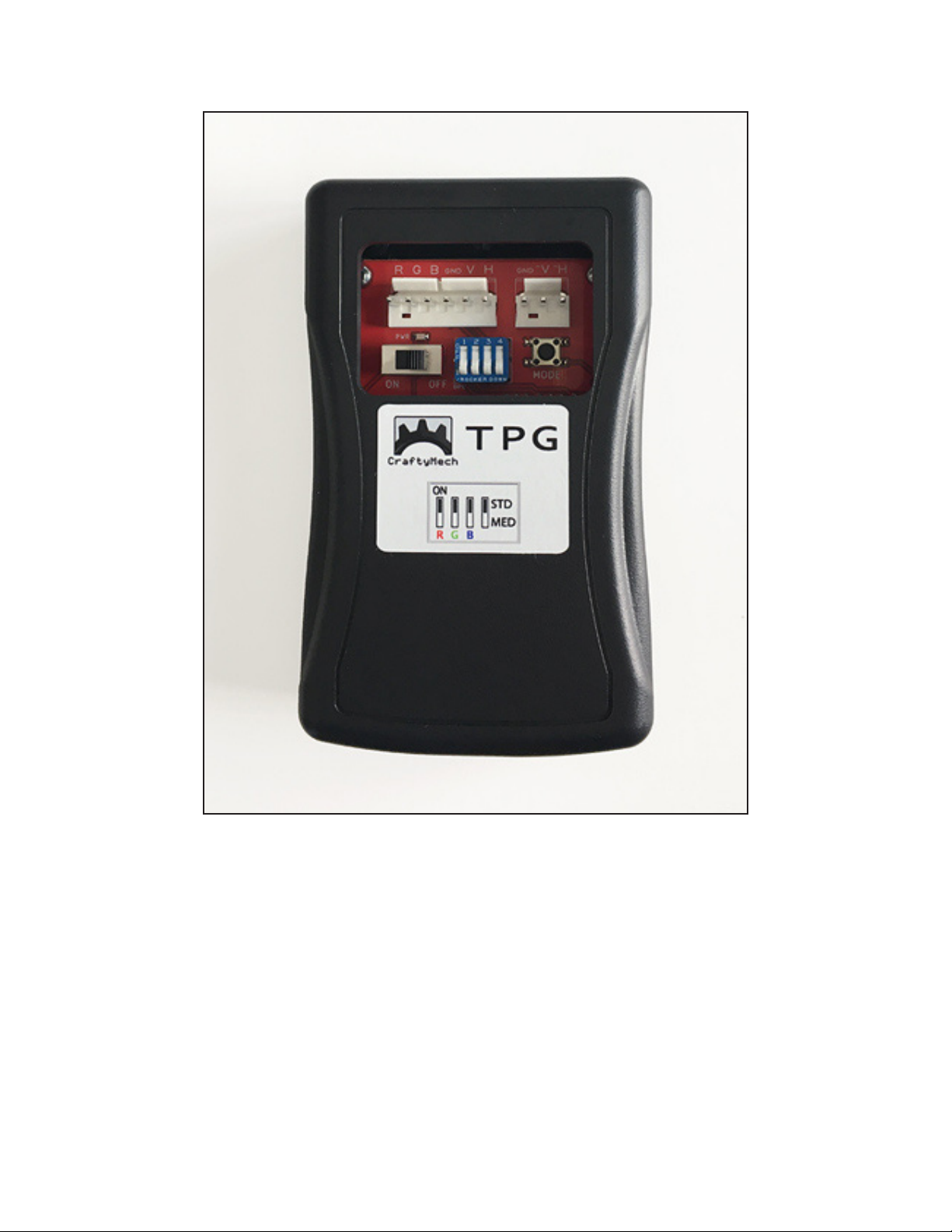
1: Output Header
e output header is a 10 pin interface for connecting the TPG to a
monitor chassis.
e layout from left to right is: R, G, B, GND, V, H, n/c, GND, -V, -H
It is recommended to use a test cable with a 4 position connector for
R,G,B,GND and a 2 position connector for the desired sync polarity.
e H output pins may be used for composite sync. If composite sync
output from the H pins is not desired, this option can be disabled from
the Menu (hold down the MODE button).
e connector pins on the output header are .156” pitch. Although
separated into two blocks of 6 and 3 pins, the output header will accept
a 10 pin connector. However, it will be easier to remove connectors from
the output header if they are split into smaller blocks (4 and 2 pins as
recommended above).

7
2: Resolution
e TPG supports Standard Resolution (15.7khz) and Medium
Resolution (24khz) modes.
e resolution is selected with position 4 of the DIP Switch, while the
unit is powered o. If the resolution is changed while the power is on, the
setting will take eect on the next power cycle.
Always double check the resolution switch setting before connecting the
TPG to a monitor chassis. Mismatching the resolution & chassis type
may result in damage to the chassis when the TPG is powered on.
Notes on Medium resolution
• ese patterns are not available: 8 Color Bars (Alternate
version), RGB Crosshatch.
• ese animations are not available: Trippy, Solar, Maze, and Hypno.

8
3: Battery Level
e TPG includes a built-in battery level indicator that is displayed
on the (1) title screen, and (2) Menu screen. When the title screen is
rst displayed, it will take about two seconds for the initial battery
measurement to complement.
e battery level is visualized as a horizontal bar lled with green to
indicate battery health. When battery level is critical, the bar will be near
empty and colored red.
e battery level will be checked periodically while the TPG is powered
on. Access the Menu (by holding down the MODE button), to view the
most recent battery reading.
e battery level is measured by checking the output of the TPG’s +5v
voltage regulator. As the 9volt battery capacity diminishes from use, the
output of this voltage regulator will drop below the nominal +5v. Critical
battery level is reached when the output of the TPG’s voltage regulator
drops below +4.5v. At this point operation will become unstable, and the
9volt battery must be replaced.
9
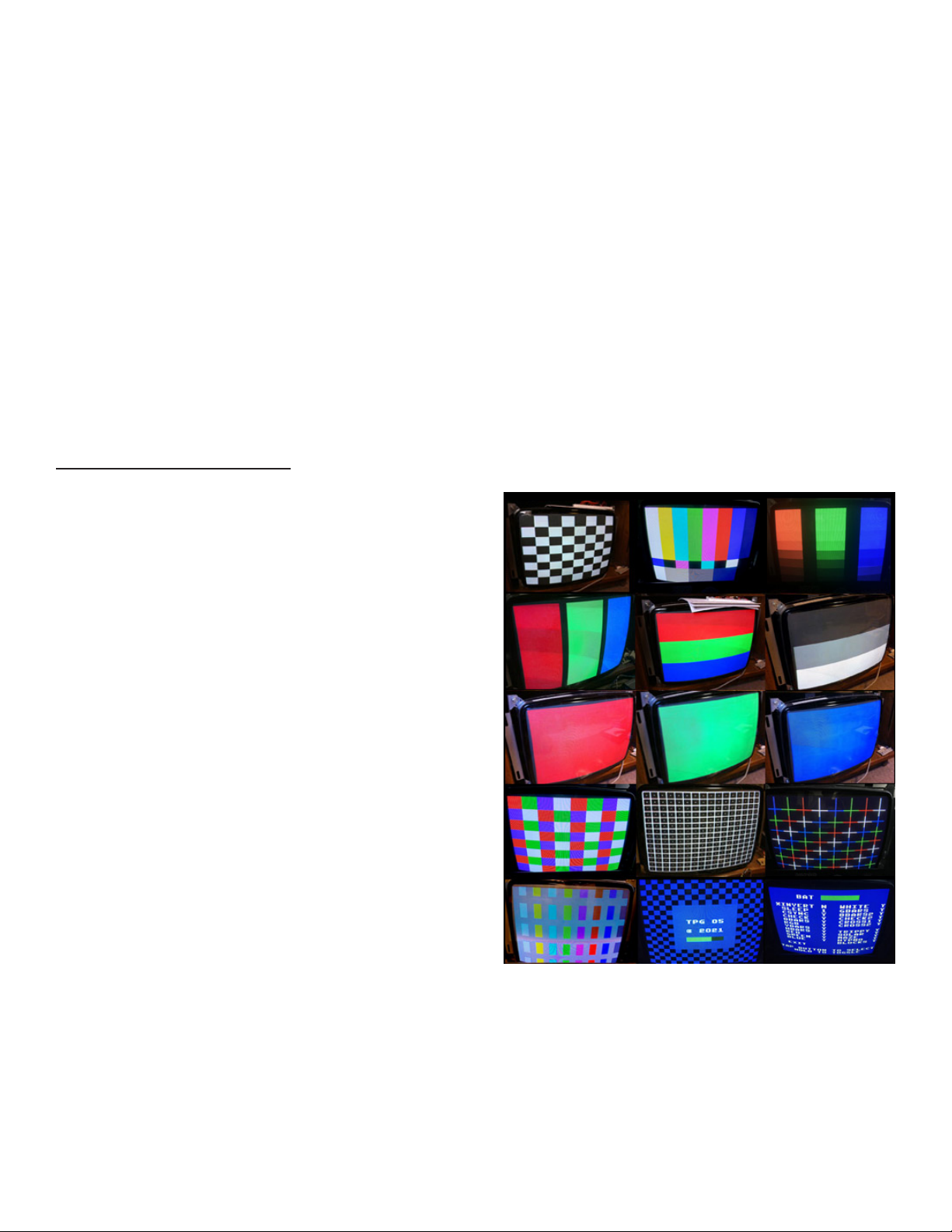
4: Patterns
e MODE button is used to select the test pattern to display. Pressing
MODE will cycle through the available patterns for the chosen resolution.
Holding down MODE will display the Menu, where patterns may be
toggled ON/OFF.
When cycling through patterns using the MODE button, only enabled
patterns will be displayed.
PATTERN LIST
Checkerboard (Black & White)
8 Color Bars
Color Gradients (R,G,B)
Vertical Bars (R,G,B)
Horizontal Bars (R,G,B)
Solid Red
Solid Green
Solid Blue
Solid White
Horizontal Bars (Black & White)
8 Color Bars (Alternate version)
Checkerboard (4 Color)
Crosshatch w/ center dots
RGB Crosshatch

10
5: Animations
e TPG includes looping sequences for verifying operation over an
extended time. ey are designed to refresh the display continously,
preventing image burn-in that might occur with a static pattern. ere are
ve animations included, which can be enabled/disabled via the Menu.
ANIMATION LIST
Trippy - is sequence plots Cos(x) while cycling the color palette, with
shrinking/expanding borders.
Solar - A vertical scrolling loop of a randomly generated solar are,
plotted with Sin(x)/x.
Maze - First made famous as a one-line code demo for the Commodore
64, this sequence is a vertically scrolling randomly generated maze.
Hypno - Don’t stare at this animation for too long! Real-time scrolling
parametric plot of Sin(x+ y).
Blocks - ese randomly positioned falling blocks stack up until they ll
the screen.

11
6: Dip Switches
e Dip Switch bank has 4 switches. Dip switches are always in one of
two states: ON or OFF. e switch numbers run from left (1) to right (4).
A switch is ON, when the top of the rocker switch is depressed. A switch
is OFF, when the bottom of the rocker switch is depressed.
Dip 1: Red Channel
OFF: Cut O (no signal) ON: Red signal active
Dip 2: Green Channel
OFF: Cut O (no signal) ON: Green signal active
Dip 3: Blue Channel
OFF: Cut O (no signal) ON: Blue signal active
Dip 4: Resolution
OFF: Medium Res ON: Standard Res

12
7: Menu
e on-screen Menu is activated by holding down the MODE button. e
Menu is only supported in Standard resolution, although the settings will
carry over to Medium resolution.
e MODE button is used to navigate the Menu options. A short press of
the MODE button will move the cursor to the next option, while a longer
press of the MODE button will toggle the option between Y/N.
Moving the cursor to EXIT, and holding down the MODE button, will exit
the Menu and re-display the last selected pattern.
BATTERY LEVEL
ere is a battery level indicator at the top of the Menu screen. is
horizontal bar will ll with green to indicate battery health. When
battery level is critical, the bar will be near empty and colored red.
SPECIAL FUNCTIONS
Invert
is feature will output an inverted signal compatible with Sanyo and
Sharp monitors used with Nintendo arcade boards. e overscan area of
the video signal is not inverted, so white borders will appear around the
test patterns (outside the display area). When inverted, the title screen
will have a blue & white checkerboard.

13
Sleep
e sleep/resume feature of the TPG is designed to save battery life if the
unit is accidently left on. When enabled, the TPG will enter a low-power
state after the congured time interval of no activity (pressing the MODE
button resets the sleep timer). When the TPG is in Sleep mode, pressing
the MODE button will resume operation by displaying the last selected
pattern.
ere are 4 time intervals that may be selected in the Menu: 15, 30,
45, and 60 minutes. ese options are represented by values of 1 (15
minutes), 2, 3, and 4 (60 minutes). e Sleep feature may be disabled by
toggling the value to N.
is function is enabled by default with a time interval of 30 minutes.
CSYNC
When enabled, this function will output a signal on the H pins suitable
for use as Composite Sync. If disabled (N), then both the H & V output
pins must be connected to the signal header on the monitor chassis to
drive the display. Disabling this function can be used to test a chassis
with a fully separated H/V sync signal. is function setting does not
take eect until exiting the Menu.
e Menu is always displayed with CSYNC enabled, to prevent a
condition where no display results from disabling CSYNC.
is function is enabled (Y) by default.

14
8: Troubleshooting
Use the following guide to help solve issues you may encounter while
using the TPG with an arcade monitor.
e monitor will not sync.
• Try both sync polarity combinations. It is recommended to rst use
-H/-V, and if the monitor will not sync, then try +H/+V.
• Check your sync connection between the TPG and chassis to ensure
that the polarity matches (-sync connected to -sync input on the
chassis, +sync connected to +sync input on the chassis). Most chassis
follow the standard Wells Gardner input pinout (from left to right) of:
R, G, B, GND, +V, +H, n/c, -V, -H
• Some chassis will not sync properly if V is connected when being fed
composite sync. If your test cable has a separate connector for sync
(recommended), try turning the sync connector so just the H pin is
connected.
• If you are sure the sync is connected properly between the TPG &
monitor chassis, then the hold/sync pot on the chassis may need to
be adjusted slightly to lock in the picture. If there are two adjustment
pots on the chassis, start with vertical, then horizontal hold.
No picture.
• Check that at least one of the three R,G,B Dip Switches=ON.
• Check battery voltage with a multi meter, a reading of at least +6.5v is
needed for stable operation of the TPG.
• Check that the resolution DIP switch matches the monitor type you
are testing (Standard or Medium resolution).

15
e TPG frequently resets back to the title screen.
• Battery voltage is approaching the critical point (< +6.5v), where the
TPG may not work properly. Replace the 9V battery.
e display is too dim/bright, or the contrast is too low/high.
Adjustment of the monitor chassis brightness/contrast pots may be
needed, to better match the RGB signal levels of the TPG.
e TPG does not enter sleep mode if left running.
• e sleep function must be enabled from the Menu (hold down the
MODE button to display the Menu).
Have a question, or issue that was not covered by the troubleshooting
guide? Please send an email to support@craftymech.com

16
8: Test Cables
e part numbers below can be used to build your own test cable for use
with the TPG. e recommended length is 6’, with a pair of connectors on
each end (4pin + 2pin).
e connector pinout is as follows, from left to right:
4pin: R,G,B, Ground
2pin: H,V
Using a separate 2pin connector for sync allows you to easily change sync
between -H/-V, and +H/+V.
Molex part numbers:
09-50-8021 Housing, 2 pin .156” x 2
09-50-8041 Housing, 4 pin .156” x 2
08-50-0134 Crimp terminal .156”
Online Resellers:
greatplainselectronics.com/products.asp?cat=86
digikey.com
mouser.com

17
Table of contents


