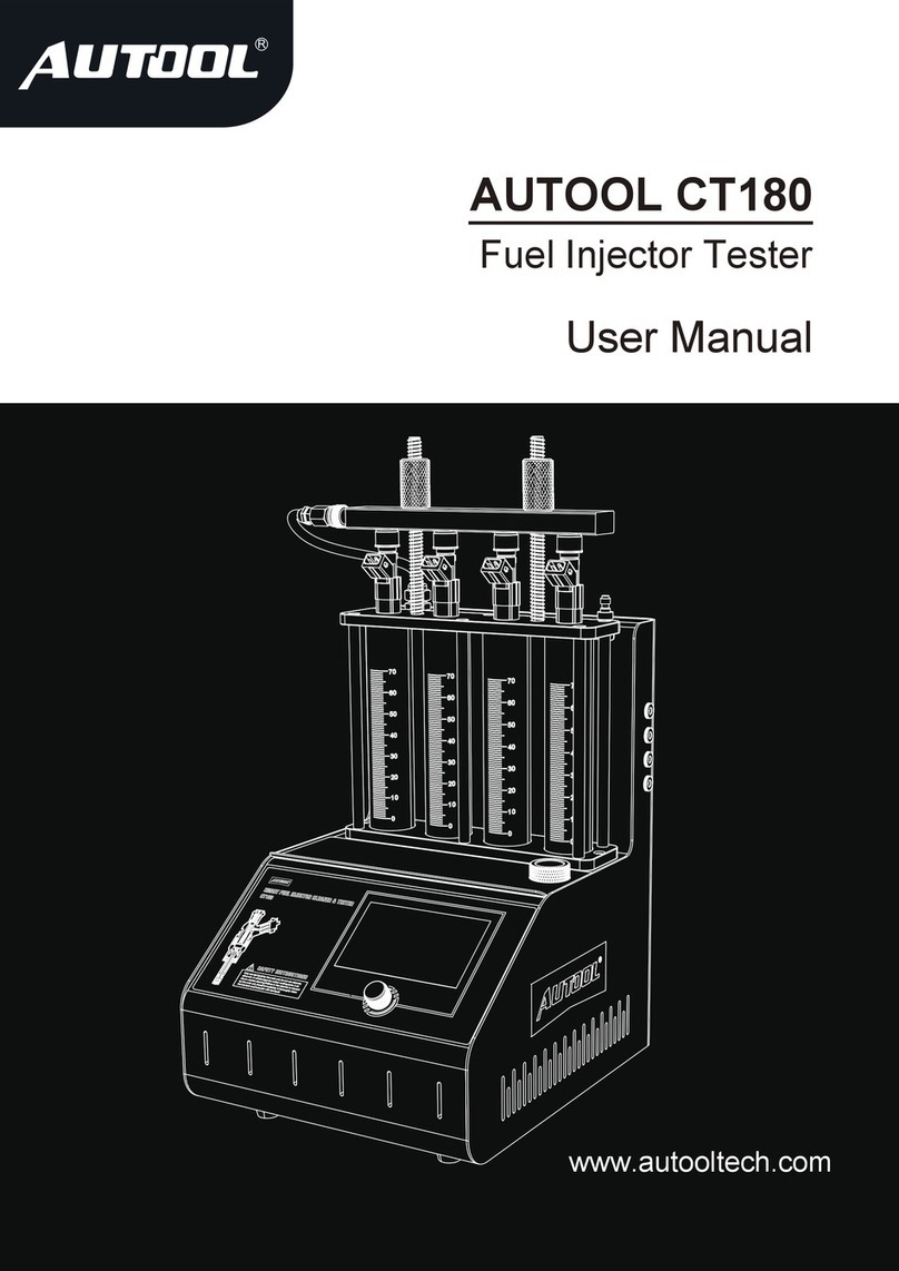
AU Tool CT400 User manual

www.autooltech.com
AUTOOL CT400
Injector Cleaner & Tester
User Manual

Copyright Information
All rights reserved by AUTOOL TECH. CO., LTD. No part of this publication may
be reproduced, stored in a retrieval system, or transmitted in any form or by any
means, electronic, mechanical, photocopying, recording or otherwise, without
the prior written permission of AUTOOL. The information contained herein is
designed only for the use of this unit. AUTOOL is not responsible for any use of
this information as applied to other units.
Neither AUTOOL nor its affiliates shall be liable to the purchaser of this unit or
third parties for damages, losses, costs, or expenses incurred by purchaser or
third parties as a result of: accident, misuse, or abuse of this unit, or unautho-
rized modifications, repairs, or alterations to this unit, or failure to strictly
comply with AUTOOL operating and maintenance instructions.
AUTOOL shall not be liable for any damages or problems arising from the use of
anyoptions or any consumable products other than those designated as
OriginalAUTOOL Products or AUTOOL Approved Products by AUTOOL.
Other product names used herein are for identification purposes only and may
betrademarks of their respective owners. AUTOOL disclaims any and all rights
in those marks.
Manual are either trademarks, registered trademarks, service marks, domain
names, logos, company names of or are otherwise the property of AUTOOL or
its affiliates. Incountries where any of the AUTOOL trademarks, service marks,
domain names, logos and company names are not registered, AUTOOL claims
other rights associated with unregistered trademarks, service marks, domain
names, logos, and company names. Other products or company names referred
to in this manual maybe trademarks of their respective owners. You may not use
any trademark, service mark, domain name, logo, or company name of
AUTOOL or any third party without permission from the owner of the applicable
trademark, service mark, domain name, logo, or company name. You may
contact AUTOOL by visiting AUTOOL at https://www.autooltech.com, or writing
to [email protected], to requestwritten permission to use Materials on
this manual for purposes or for all other questions relating to this manual.

Table of Contents
Overview
1.1 Functions and features
1.2 Working environment and technical parameters
Structure
2.1 Overview structure
2.2 Control panel
Operation Procedures
3.1 Ultrasonic cleaning
3.2 Test functions
Maintenance
Precautions
Warranty
1
1
2
3
3
3
4
4
5
8
9

Overview
1.1 Functions and features
This GDI Fuel Injector 6-cylinder Cleaner and Tester is a great upgrade, which
adapts the latest GDI design. It not only can be used to clean and test the
standard injectors, of note that it can carry out GDI injectors cleaning and tesst.
It comes with multi voltages available for GDI injectors, which enables to adapt
for different types of injector testing. The machine is the necessary and preferred
equipment for the automotive serving and maintenance, research, and teaching
training departments.
Functions
● Ultrasonic cleaning: To perform simultaneous cleaning on one or several
injectors and to remove the carbon deposits on the injector completely.
● Uniformity test: To test the uniformity of injecting amount of each injector.
● Sprayability test: To monitor the spraying status of each injector with the
help of a backlight.
● Leakage test: To test the sealing and dribbling conditions of injectors under
system pressure.
● Injecting flow test: To check the injecting amount of the injector under
specific working parameters (e.g. same time, same number of times).
● Automatic test: Under specific working parameters, test injectors by
simulating different working conditions.
● Adopted with the latest unique GDI fuel injector driving software, which can
drive 12V, 70V, 120V high-pressure fuel injectors.
Features
● Adopting the powerful ultrasonic cleaning technology, the equipment offers
complete cleaning to the injectors.
● Fuel pressure control through microcomputer offers stable pressure control
and large adjustable range.
● Adopting high-definition digital control panel display, it makes the operation
simple and easy to learn.
● Test liquid level can be displayed visually. It can also be recovered for
recycling use.
● With the help of the bright background light of the LED, it is possible to
clearly observe the various working conditions of the injectors.
● Replaceable composite coupling with patented and suitable for many
models.
● The test time, operating frequency, number of injecting, and minimum
switching pulse width of the injector can be adjusted freely within the allowed
adjustment range.
1

1.2 Working environment and technical parameters
Working environment
● Power supply: AC 110/220V ±10%
● Frequency: 50-60HZ±0.5
● Relative humidity: <85%
● Ambient temperature: 0℃~+40℃
● External magnetic field strength: <400A/m
● No open flames are allowed around
Technical parameter
● Fuel tank capacity: 1500 ml
● Test tube amount: 140 ml
● RPM range: 0~7500 r/min
● Time range: 0~9900 times
● PWM pulse width: 0~20.0 ms
● System pressure: 0~0.55Mpa (adjustable)
● Timing: 0~20 minutes adjustable
● Ultrasonic cleaning power: 60W (intermittent work)
● Ultrasonic cleaning frequency: 28 KHZ±0.5 KHZ
● Dimensions: 390mm (length) × 410mm (width) × 430 mm (height)
● Weight: 16.6KG
2

Structure
2.1 Overview structure
1- Filling inlet; 2- Test tube; 3- Drain button; 4- Control panel;
5- Pulse signal cable; 6- Ultrasonic cleaning bath; 7- Power switch;
8- Power socket; 9- Pressure gauge; 10- Test liquid drain valve;
2.2 Control panel
● Pulse width display: function options and pulse width adjustment.
● Display of working hours/injecting times: display the working hours and
injecting times of the injectors.
● Start key: press to execute the selected work item.
● Function menu selection buttons.
● Pause key: Press it to temporarily stop the selected work item.
● Time and frequency adjustment button: adjust the working time and spray
frequency of the fuel injector.
● Stop key: stop the selected work item and return to the selected work item.
● Pressure decrease adjustment button.
3

● Pressure increase adjustment button.
● Text description of function menu.
How to use the drain button
When performing work items 8, 9, and 10, press the button to close the drain
valve. Then the oil injected by the fuel injectors is closed in the glass tube, so as
to compare the amount of oil injected by each fuel injector. After the observation,
open the oil drain valve and return the test liquid to the oil tank.
Operation Procedures
3.1 Ultrasonic cleaning
Injector Cleaner takes advantage of the penetrability and cavitation impact
wave caused by ultrasonic waves traveling through the middle to provide
powerful cleaning on objects with complex shapes, cavities, and pores so that the
stubborn carbon deposits can be removed from the injectors.
Preparation:
● Remove the injector from the vehicle engine to check the rubber seals inside
for damage. Replace the damaged rubber seals with another same type of
rubber seal to avoid leakage during testing. Put the outside of injectors in
gasoline or detergent, and wipe them with a soft cloth after cleaning the outside
oil sludge carefully.
● Turn on the power (Note: There will be a delay of several seconds when this
device is restarted after a long power disconnection).
● Take out the cleaning bracket from the accessory box, then put it into the
ultrasonic bath, and put the clean fuel injector in the positioning hole of the
cleaning bracket in the ultrasonic bath.
3.1.2 Operation steps
Ultrasonic Cleaning:
● Add appropriate injector cleaning liquid into the ultrasonic bath, which
slightly immerses over the cleaning bracket will be fine.
● Turn on the ultrasonic switch on the right side of the main unit to start
ultrasonic cleaning.
● During the ultrasonic cleaning process, pulse signals can be input to the fuel
injector.
Steps:
● Plug the injector pulse signal wires into injectors respectively in turn. (Special
injectors need to be connected with adapter wires).
● Press the item selection up and down keys to select the "01 Ultrasonic
Cleaning" item, and then press the working time up and down keys to set the
4

time. (The system defaults to 10 minutes, if you need to modify the time, you can
change it with the up and down keys)
● Press the run key, and the system starts to input pulse signals.
When finished cleaning, take out the injectors from the ultrasonic tank. Wipe off
the cleaning liquid with a soft cloth and prepare for the next operation.
Notes:
● During the cleaning process, you can hear the intermittent vibration when
you take the fuel injector out and put it near your ear, which can determine
whether the injector has a pulse signal.
● Before the injector detergent is added into the ultrasonic cleaner, do not turn
on the ultrasonic cleaner. Otherwise, damage may be incurred.
● Only the ultrasonic cleaning liquid matched with the machine can be added
to the ultrasonic tank, and other cleaning liquid can not be used instead,
otherwise, the surface coating of the equipment and the mask will peel off, which
will not be covered by the warranty.
3.2 Test functions
This function is to detect the sprayability, dripping, blockage, fuel injecting
angle of the fuel injectors and the amount and uniformity of the fuel injection of
each fuel injector at different RPM.
3.2.1 Preparation
● Add test liquid. Pour the test liquid from the filling port. (Approximately
1000ML is added, and the liquid level should not be lower than 800ML every
time)
● Installation of fuel injectors
Schematic diagram of injector installation
A. Install the injector adapter and the plug into the Fuel distributor assembly
B. Install the fuel injector in the forward direction (apply a little grease on the "O"
ring of the fuel injector)
5
Adapter for fuel
injector
Injector
Fuel distributor
assembly

C. Install the fuel distributor assembly and the fuel injectors on the Top assem-
bly plate and tighten and fix it with a fixed screw nut and a fixed screw sleeve.
Get ready to test.
D. Select 12v/70v/120v according to injector type.
3.2.2 Steps:
Item 02 idle speed test:
● Connect the quick connector of the black outlet hose on the machine with
the male end connector on the fuel distributor assembly, and insert the pulse
line of the fuel injector.
● Press the item selection up and down keys to select the "02 Idle Speed
Test" item.
● Press the working time up and down keys to set the time. (Normally set to
10 minutes)
● Press the “run” key to start working.
● Rotate the pressure adjustment knob to adjust the pressure to 2-5 kg.(In the
electronic spraying system, the oil pressure is generally 2-5 kg).
● Press the up and down keys to select the appropriate pulse width. (The
system defaults to 3MS, generally adjusted to 3MS).
● The working time will gradually decrease, and when it reaches 0, the
system will stop automatically.
03 middle-speed test:
● Press the item selection up and down keys to select the "03 middle-speed
test" item.
● Press the RUN button.
● The rest of the operation steps are consistent with item 02.
04 High-speed tests:
● Press the item selection up and down keys to select the "04 High-speed
test" item.
● Press the RUN button.
● The rest of the operation steps are consistent with item 02
05 Accelerated test:
● Press the project selection up and down keys to select the "05 Accelerated
test" item.
● Press the RUN button.
Notes:
1)The fuel pressure, working time and pulse width are automatically set by the
system. The time system presets 10s as a loop cycle, which can be set by the
user.
6

7
2)The system will automatically loop three times in a row to simulate the working
conditions and fuel spraying amount of the fuel injectors when the engine is
accelerating uniformly at 1,500 -15,000 rpm.
06 Various speed test:
● Press the item selection up and down keys to select the "06 Various speed
est" item.
● Press the RUN button.
Notes:
1)The fuel pressure, working time and pulse width are automatically set by the
system. The time system presets 10s as a loop cycle, which can spare the labor
of setting by the user.
2)The system will automatically loop three times in a row to simulate the working
conditions and fuel spraying amount of the fuel injectors when the engine is
idling (1,500 rpm), middle-speed (9,000 rpm), and high-speed (15,000 rpm).
07 Leakage test:
● Press the item selection up and down keys to select the "07 Leakage test"
item.
● Press the working time selection keys to set the time. (Generally set to 1
minute)
● The remaining operation steps are consistent with item 02.
Notes:
1)The pulse width system is preset to 3ms, no need to set it again.
2)Simulate whether the fuel injectors drip and leak when the oil pressure of the
vehicle is 0.3Mpa.
tem 08 Idle fuel injecting amount test:
● Press the item selection up and down keys to select the "08 Idle fuel
injecting amount test" item.
● Press the up and down keys to set the number of times of injection.
(Generally set to 2,000 times)
● The remaining operation steps are consistent with item 02.
Notes:
1)Simulates the working condition and injection amount of the engine at idle
speed when the injectors work a certain number of times.
09 Middle-speed fuel injecting amount test:
● Press the item selection up and down keys to select the item "09
Middle-speed fuel injecting amount test".
● The rest of the operation steps are consistent with item 08.
10 High-speed fuel injecting amount test:

8
● Press the item selection up and down keys to select the "10 High-speed fuel
injecting amount test" item.
● The rest of the operation steps are consistent with item 08.
Notes:
1)Uniformity. This is for checking the uniformity carried out at various rpm.
When the test liquid level is at 2/3 of the test tube, please pause or stop the
machine to observe the uniformity of the injecting amount. Injecting difference of
all injectors on one vehicle should be kept within 2%. Or refer to the relevant
technical manual of the fuel injector to determine the uniformity of the injecting
amount.
2)Observe the shape of the injectors. Observe whether the injecting shapes and
angles of all fuel injectors on the same vehicle are identical at various speeds.
At the same time, you can adjust the injection pulse width of the fuel injectors to
compare whether the minimum injection pulse width among the fuel injectors is
consistent.
3) Leakage test. Leakage test is to inspect the sealing conditions of the injector
needle valve under system pressure. (Observe the tightness of the fuel injectors,
generally, there should be no leakage within one minute)
11 Reverse Flush Test:
● Press the item selection up and down keys to select "11 Reverse Flush",
and install the injectors in the opposite direction for cleaning.
12 Fully Automatic Cleaning items:
● Cleaning time can be set to a maximum of 20 minutes. Please connect to
various special parts that can clean the combustion chamber or throttle.
Maintenance
1. Tidy up
● Turn off the power and unplug the power plug.
● Put all the connectors back into the accessory box for storage.
● Put the ultrasonic cleaner back into the original bottle and seal it, and wipe
the equipment clean with a dry soft cloth.
● If it is not used for a long time, open the test liquid valve and drain the test
liquid back into the original bottle for sealed preservation.
2. Maintenance
Replacement of test liquid
● Impurities can be built up in the test liquid after being used for a period of
time. Do not use contaminated test liquid, otherwise, injector and fuel pumps

9
can be blocked. Drain the test liquid by removing the level indicator on the left of
the main unit. It is better to clean the fuel tank with a little test liquid before the
tank is filled in with the new liquid. After cleaning, close the test liquid valve
again and pour in new test liquid.
Replacement of Fuse
● There is a square box marked with a fuse at the power socket on the left
side of the equipment, and the fuse can be seen by opening the square box. If it
is blown, replace it with a new one (5A).
Precautions
● Since the test device is quartz glass, which is easy to be broken, please
don't place other objects around the device to avoid breaking by bumping.
● If there is no digital display after power on (there may be a delay of several
seconds), please check whether the power supply has electricity; if there is a
power failure, please check whether the plug is firmly connected, or check
whether the fuse is blown. If there is no break, and the switch is still not working
after pressing several times, please contact your local dealer, do not disassem-
ble it by yourself, otherwise our company shall not warranty.
● Do not switch on the ultrasonic system when there is no ultrasonic
detergent in the ultrasonic cleaning chamber. Otherwise, damage to the
ultrasonic cleaner can result.
● It must be emptied completely before adding 1000ml of test liquid for every
test liquid change.
● The use of unqualified test liquid will cause corrosion of the pump and oil
supply line and failure of the pressure gauge.
● Only the ultrasonic cleaning liquid matched with the machine can be added
to the ultrasonic bath, and other cleaning liquid can not be used instead,
otherwise, the surface coating of the equipment and the mask will peel off, which
will not be covered by the warranty.
● Kerosene, gasoline, pure water and other testing and cleaning solutions are
strictly forbidden to be used as the testing and cleaning solution for this equip-
ment. Otherwise, it will damage the "O" ring and rubber parts of the pipeline
inside the equipment and cause leakage.
● Do not mix cleaning liquid with testing liquid.
● Please place the machine on a flat surface and use the four feet to support
the weight of the machine, otherwise the ultrasonic cleaning bath will be
damaged, which is not covered by the warranty.

Warranty
● Thank you for choosing our products, we will provide you with the following
services and promises.
● The warranty period of this product is 1 year.
● After the warranty period expires, repairs will be charged for replacement
parts.
● After the failure, please contact the manufacturer, we will give you the most
complete service in the
shortest time.
The following items are not covered by the warranty:
● Vulnerable parts are not covered by the warranty, including: glass tube, signal
sire, stickers, connectors pressure gauge, oil outlet pipe.
● When no cleaning agent is added to the ultrasonic tank, turning on the
ultrasonic
cleaning switch will damage the ultrasonic system, which is not covered by the
warranty.
● If the testing agent is not replaced in time after long-term use, the oil pump
filter
screen is blocked and the oil pump is burned out of the warranty.
● The use of fuel injector cleaning agent as fuel injector testing agent will cause
the
fuel pump to burn out, which is not covered by the warranty.
● Man-made faults are not covered by the warranty.
Disclaimer: All information, illustrations, and specifications contained in this
manual, AUTOOL resumes the right of modify this manual and the machine itself
with no prior notice. The physical appearance and color may differ from what is
shown in the manual, please refer to the actual product. Every effort has
been made to make all descriptions in the book accurate, but inevitably there
are still inaccuracies, if in doubt, please contact your dealer or AUTOOL
after-service centre, we are not responsible for any consequences arising from
misunderstandings.

深圳市偶然科技有限公司
广东省深圳市宝安区北八路航城锦驰产业园
Shenhua Innovation Park, Baoan, Shenzhen, China
www.autooltech.com
+86-400 032 0988 / +86-755-27807580
Table of contents
Other AU Tool Test Equipment manuals
AU Tool
AU Tool CT180 User manual
AU Tool
AU Tool BT 260 User manual
AU Tool
AU Tool BST-100 User manual
AU Tool
AU Tool CT500 User manual
AU Tool
AU Tool LM708 User manual
AU Tool
AU Tool BST-100 User manual

AU Tool
AU Tool BT-660 User manual
AU Tool
AU Tool SPT360 User manual
AU Tool
AU Tool BT160 User manual
AU Tool
AU Tool BT70 User manual
