EcoWater ESS1102XR32 User manual

OWNER’S MANUA
How to install, operate and maintain your
EcoWater Systems
Solid State Timer Water System
EcoWater Systems LL
P.O. Box 64420, St. Paul, MN 55164-0420
www.ecowater.com
Designed, Engineered &
Assembled in the U.S.A.
System tested and certified by the
Water Quality Association against SA B483.1.
System tested and certified by NSF International
against NSF/ANSI Standard 44
for hardness reduction,
and certified to NSF/ANSI Standard 372.
7365972 (Rev. A 5/16/17)
Model
ESS1102XR32

2
ECOWATER
SYSTEMS Table of Contents, Inspect Shipment & Safety Guides
TAB E OF CONTENTS
Page
Warranty . . . . . . . . . . . . . . . . . . . . . . . . . . . . . . . . . . . . . . . . . . . . . . . . . . . . . . . . . . . . . . . . . . . . . . . . . . . . . . . . . . 3
Specifications & Performance laims . . . . . . . . . . . . . . . . . . . . . . . . . . . . . . . . . . . . . . . . . . . . . . . . . . . . . . . . . . . . 4
Dimensions . . . . . . . . . . . . . . . . . . . . . . . . . . . . . . . . . . . . . . . . . . . . . . . . . . . . . . . . . . . . . . . . . . . . . . . . . . . . . . . . 5
Before Starting Installation . . . . . . . . . . . . . . . . . . . . . . . . . . . . . . . . . . . . . . . . . . . . . . . . . . . . . . . . . . . . . . . . . . . . 6
Media Loading . . . . . . . . . . . . . . . . . . . . . . . . . . . . . . . . . . . . . . . . . . . . . . . . . . . . . . . . . . . . . . . . . . . . . . . . . . . . . . 7
Typical Installation Illustrations . . . . . . . . . . . . . . . . . . . . . . . . . . . . . . . . . . . . . . . . . . . . . . . . . . . . . . . . . . . . . . . . . 8
Installation Instructions . . . . . . . . . . . . . . . . . . . . . . . . . . . . . . . . . . . . . . . . . . . . . . . . . . . . . . . . . . . . . . . . . . . . . 9-12
Sanitizing Procedure . . . . . . . . . . . . . . . . . . . . . . . . . . . . . . . . . . . . . . . . . . . . . . . . . . . . . . . . . . . . . . . . . . . . . . . . 12
Programming the Electronic ontroller . . . . . . . . . . . . . . . . . . . . . . . . . . . . . . . . . . . . . . . . . . . . . . . . . . . . . . . 13-19
Programming the Electronic ontroller (Softeners) . . . . . . . . . . . . . . . . . . . . . . . . . . . . . . . . . . . . . . . . . . . 13-14
ontroller Features / Options (Softeners) . . . . . . . . . . . . . . . . . . . . . . . . . . . . . . . . . . . . . . . . . . . . . . . . . . . . . 15
Programming the Electronic ontroller (Filters) . . . . . . . . . . . . . . . . . . . . . . . . . . . . . . . . . . . . . . . . . . . . . . . . 16
ontroller Features / Options (Filters) . . . . . . . . . . . . . . . . . . . . . . . . . . . . . . . . . . . . . . . . . . . . . . . . . . . . . 16-17
Features (All Models) . . . . . . . . . . . . . . . . . . . . . . . . . . . . . . . . . . . . . . . . . . . . . . . . . . . . . . . . . . . . . . . . . 17-19
Wiring Schematic . . . . . . . . . . . . . . . . . . . . . . . . . . . . . . . . . . . . . . . . . . . . . . . . . . . . . . . . . . . . . . . . . . . . . . . . . . 18
Routine Maintenance . . . . . . . . . . . . . . . . . . . . . . . . . . . . . . . . . . . . . . . . . . . . . . . . . . . . . . . . . . . . . . . . . . . . . 20-21
Troubleshooting . . . . . . . . . . . . . . . . . . . . . . . . . . . . . . . . . . . . . . . . . . . . . . . . . . . . . . . . . . . . . . . . . . . . . . . . . 22-23
Repair Parts . . . . . . . . . . . . . . . . . . . . . . . . . . . . . . . . . . . . . . . . . . . . . . . . . . . . . . . . . . . . . . . . . . . . . . . . . . . . 24-27
Recommended maximum allowable inlet water
pressure is 125 psi. If daytime pressure is over 80
psi, nighttime pressure may exceed the maximum.
Use a pressure reducing valve if necessary. Be sure
the addition of a pressure reducing valve will not
reduce the flow to less than the 3 gallons per minute.
The water softener works on 24V DC electrical power,
supplied by a direct plug-in power supply (included).
Be sure to use the included power supply, and plug it
into a nominal 120V, 60 Hz household outlet that is in
a dry location only, grounded and properly protected
by an overcurrent device such as circuit breaker or
fuse.
This system is not intended to be used for treating
water that is microbiologically unsafe or of unknown
quality without adequate disinfection before or after
the system.
European Directive 2002/96/E requires all
electrical and electronic equipment to be
disposed of according to Waste Electrical
and Electronic Equipment (WEEE) require-
ments. This directive or similar laws are in
place nationally and can vary from region to
region. Please refer to your state and local
laws for proper disposal of this equipment.
Follow the installation instructions carefully. Failure to
install the water softener properly voids the warranty.
Before you begin installation, read this entire manual.
Then obtain all the materials and tools you will need
to make the installation.
Check local plumbing and electrical codes. The
installation must conform to them.
Use only lead-free solder and flux for all sweat-sol-
der connections as required by state and federal
codes.
Use care when handling the water softener. Do not
turn upside down, drop, or set on sharp protrusions.
Do not locate the water softener where freezing tem-
peratures occur. Do not attempt to treat water over
120°F. Freezing, or hot water damage voids the war-
ranty.
Avoid installing in direct sunlight. Excessive sun heat
may cause distortion or other damage to non-metallic
parts.
The water softener requires a minimum water flow of
3 gallons per minute at the inlet.
The parts required to assemble and install the water
softener are included with the unit. Thoroughly check
the water softener for possible shipping damage and
parts loss. Also inspect and note any damage to the
shipping carton.
Remove and discard (or recycle) all packing materials.
To avoid loss of small parts, we suggest you keep the
small parts in the parts bag until you are ready to use
them.
INSPECT SHIPMENT
SAFETY GUIDES

3
ECOWATER
SYSTEMS Warranty
LIMITED WARRANTY
EcoWater Systems C Advantage Warranty
ESS1102XR32 Water onditioning System
ongratulations! You have just purchased the highest quality water conditioning product on the market.
To whom is this warranty extended?
EcoWater Systems LL warrants its products to the original owner and guarantees that the products will be free from defects
in materials and workmanship from the original date of installation.
How does my warranty work?
If, during the respective warranty period, a part proves, after inspection by EcoWater, to be defective, EcoWater will, at its sole
option repair or replace that part at no charge, other than normal shipping, installation or service charges.
What is covered by the warranty?
EcoWater Systems LL guarantees that,
for the LIFETIME of the original owner, the MINERAL TANK will not rust, corrode, leak, burst, or in any other manner fail to per-
form its proper functions and that,
for a period of TEN (10) YEARS after installation, the SALT TANK will be free of defects in materials and workmanship and will
perform its proper function and that,
for a period of THREE (3) YEARS after installation, the VALVE BODY, ELE TRONI FA EPLATE and ALL OTHER PARTS
will be free of defects in materials and workmanship and will perform their normal functions.
How do I obtain warranty service?
Should you need service, your local, independent EcoWater Dealer is only a phone call away.
PHONE:____________________________________________________________
To obtain warranty service, notice must be given, within thirty (30) days of the discovery of the defect, to your local EcoWater
Systems dealer.
If I need a part replaced after the factory warranty expires, is the replacement part warranted?
Yes, EcoWater Systems LL warrants FA TORY REPAIRS as well as all REPLA EMENT PARTS for a period of 90 DAYS.
This warranty does not include normal shipping, installation or service charges.
Are any additional warranties available?
We are pleased to say, YES! EcoWater Systems LL sells an EXTENDED, PARTS ONLY WARRANTY for the ELE TRONI S
portion of your product. This warranty is called the "Perfect Ten" and extends the three year warranty on the electronic FA E-
PLATE, WIRING HARNESS, DRIVE MOTOR, POWER SUPPLY, POWER ORD, SENSOR HOUSING, and MI RO SWIT H-
ES to a total of TEN YEARS from the date of original installation. Your local dealer will provide details regarding this warranty
or will refer you to the factory for additional information. Should your local dealer not offer this warranty, you may contact the
factory for additional information.* This guarantee may be subject to normal shipping and installation or service charges.
General Provisions
The above warranties are effective provided the water conditioner is operated at water pressures not exceeding 125 psi, and
at water temperatures not exceeding 120°F; provided further that the water conditioner is not subject to abuse, misuse, alter-
ation, neglect, freezing, accident or negligence; and provided further that the water conditioner is not damaged as the result of
any unusual force of nature such as, but not limited to, flood, hurricane, tornado or earthquake. EcoWater Systems LL is
excused if failure to perform its warranty obligations is the result of strikes, government regulation, materials shortages, or other
circumstances beyond its control.
*THERE ARE NO WARRANTIES ON THE WATER ONDITIONER BEYOND THOSE SPE IFI ALLY DES RIBED ABOVE. ALL IMPLIED
WARRANTIES, IN LUDING ANY IMPLIED WARRANTY OF MER HANTABILITY OR OF FITNESS FOR A PARTI ULAR PURPOSE, ARE
DIS LAIMED TO THE EXTENT THEY MIGHT EXTEND BEYOND THE ABOVE PERIODS. THE SOLE OBLIGATION OF E OWATER SYS-
TEMS LL UNDER THESE WARRANTIES IS TO REPLA E OR REPAIR THE OMPONENT OR PART WHI H PROVES TO BE DEFE -
TIVE WITHIN THE SPE IFIED TIME PERIOD, AND E OWATER IS NOT LIABLE FOR ONSEQUENTIAL OR IN IDENTAL DAMAGES. NO
E OWATER DEALER, AGENT, REPRESENTATIVE, OR OTHER PERSON IS AUTHORIZED TO EXTEND OR EXPAND THE WARRANTIES
EXPRESSLY DES RIBED ABOVE.
Some states do not allow limitations on how long an implied warranty lasts or exclusions or limitations of incidental or conse-
quential damage, so the limitations and exclusions in this warranty may not apply to you. This warranty gives you specific legal
rights, and you may have other rights which vary from state to state. This warranty applies to consumer-owned installations only.

4
SPECIFICATIONS
Model ESS1102XR32
Model ode ST31
Rated Softening apacity (grains @ lb. salt dose)
13,400 @ 2.9
28,600 @ 9.2
34,400 @ 15.6
Rated Efficiency (grains / lb. @ minimum salt dose) 4,620 @ 2.9
Water Used During Regeneration @ Minimum Salt Dose 56.2 gal. / 1,000 grains
Amount of High apacity Resin 51 lbs. (0.98 cu. ft.)
Resin Tank Nominal Size (dia. x height) 10 x 47 in.
Service Flow Rate 8.3 gpm
Pressure Drop at Rated Service Flow 14.9 psig
Intermittent Flow @ 15 psi p8.3 gpm
Intermittent Flow @ 30 psi p12.2 gpm
Water Supply Maximum Hardness 110 gpg
Water Supply Maximum lear Water Iron ¢5 ppm
Min. - Max. Water Supply Pressure u20 - 125 psi
Min. - Max. Water Supply Temperature 40 - 120 °F
Minimum Water Supply Flow Rate 3 gpm
Max Drain Flow Rate 2.2 gpm
pIntermittent flow rate does not represent the maximum service flow rate used
for determining the unit’s rated capacity and efficiency. ontinuous operation at
flow rates greater than the service flow rate may affect capacity and efficiency
performance.
¢apacity to remove clear water iron is substantiated by independent laboratory
test data. State of Wisconsin requires additional treatment if water supply con-
tains greater than 5 ppm clear water iron.
uanada working pressure limits: 1.4 - 7.0 kg/cm².
This system, when containing EcoWater Systems resin part number 0502272 in the
amount listed above, conforms to NSF/ANSI 44 for the specific performance claims
as verified and substantiated by test data.
This softener has a rated softener efficiency of not less than 3,350 grains of total hardness exchange per pound of
salt (based on sodium chloride). This softener has been proven to deliver soft water for at least ten continuous min-
utes at the rated service flow rate. The rated salt efficiency is measured by laboratory tests described in NSF/ANSI
Standard 44. These tests represent the maximum possible efficiency that the system can achieve. Operational effi-
ciency is the actual efficiency after the system has been installed. It is typically less than the rated efficiency, due to
individual application factors including water hardness, water usage, and other contaminants that reduce a softener's
capacity.
ECOWATER
SYSTEMS Specifications & Performance Claims

5
ECOWATER
SYSTEMS Dimensions
FIG. 1
32”
BRINE TANKMEDIA TANK
IN - OUT
36-9/16”
3-3/8”
14” 16”
14” 16”
56-5/8”
49-3/4”
6
ECOWATER
SYSTEMS Before Starting Installation
WHERE TO INSTA THE SOFTENER
= To soften all water in the home, install the water
softener close to the water supply inlet, upstream
of all other plumbing connections, except outside
water pipes. Outside faucets should remain on
hard water to conserve salt and softening capacity.
= Place the softener near a floor drain, or other
acceptable drain point (laundry tub, sump, stand-
pipe, etc.) to carry away regeneration discharge
water.
= onnect the softener to the main water supply
pipe UPSTREAM OF the water heater. DO NOT
RUN HOT WATER THROUGH THE SOFTENER.
The temperature of water passing through the sof-
tener must be less than 120°F.
= Do not install the softener in a place where it could
freeze. Damage caused by freezing is not cov-
ered by the warranty.
= Put the softener in a place water damage is least
likely to occur if a leak develops. The manufactur-
er will not repair or pay for water damage.
= A 120V, 60 Hz electrical outlet, to plug the included
power supply into, is needed near the softener.
Be sure the electrical outlet and power supply are
in an inside location, to protect from wet weather.
= If installing in an outside location, you must take
the steps necessary to assure the softener, instal-
lation plumbing, wiring, etc., are as well protected
from the elements, contamination, vandalism, etc.,
as when installed indoors.
= Keep the softener out of direct sunlight. The sun's
heat may soften and distort plastic parts.
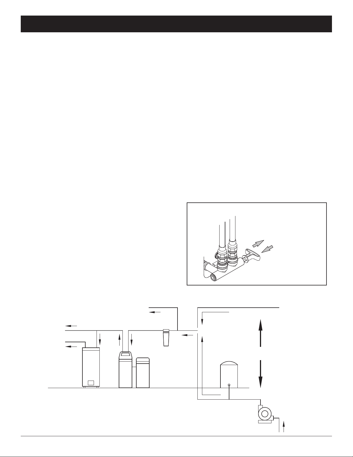
THE PROPER ORDER TO INSTA WATER TREATMENT EQUIPMENT
FIG. 3
Pressure
Tank
City Water Supply
Well Water Supply
Well
Pump
OR
Optional
Sediment
Filter
Water
Heater
Water
Softener
Untreated Water to
Outside Faucets
Hot Water
to House
old Water
to House
FIG. 2
SING E BYPASS VA VE
Pull out for “Service”
(Soft water)
Push in for
“Bypass”
TOO S, PIPE & FITTINGS,
OTHER MATERIA S YOU WI NEED
= ALWAYS install an EcoWater Systems bypass valve,
or a 3-valve bypass system. Bypass valves let you
turn off water to the softener for repairs if needed,
but still have water available to the house pipes.
= Plastic inlet and outlet fittings are included with the
softener, which allow water flow equivalent to 1 inch
nominal pipe. To maintain maximum valve flow, 1”
pipes to and from the softener fittings are recommend -
ed. Do not reduce the pipes to less than 3/4” size.
= Use copper, brass or PEX plastic pipe and fittings.
= Drain hose, 1/2” inside diameter minimum, is needed
for the valve drain.
= If a rigid valve drain is needed, to comply with
plumbing codes, you can buy the parts needed to
connect a 1/2” minimum copper tubing drain.
NOTE: The ommonwealth of Massachusetts plumbing
code 248- MR shall be adhered to. A licensed plumber
shall be used for this installation.
7
ECOWATER
SYSTEMS Media oading
MEDIA OADING
Model ESS1102XR32, as manufactured, contains no
media. Before plumbing the system, load media (See
table on Page 13 for amounts):
1. Move the system into installation location and set it
on a flat, level surface.
2. Take off the unit’s top cover and unplug the wiring
connections between the valve and the control
board (PWA).
3. Remove retainer clips and clamp sections from the
tank neck and carefully lift the valve off the tank.
4. Remove the top distributor from the tank neck,
leaving the bottom distributor (including riser pipe)
in place. enter the distributor in the tank.
5. With a pail or hose, fill the tank with about 12” of
water. The water acts as a cushion to protect the
bottom distributor while filling the tank with gravel
and media.
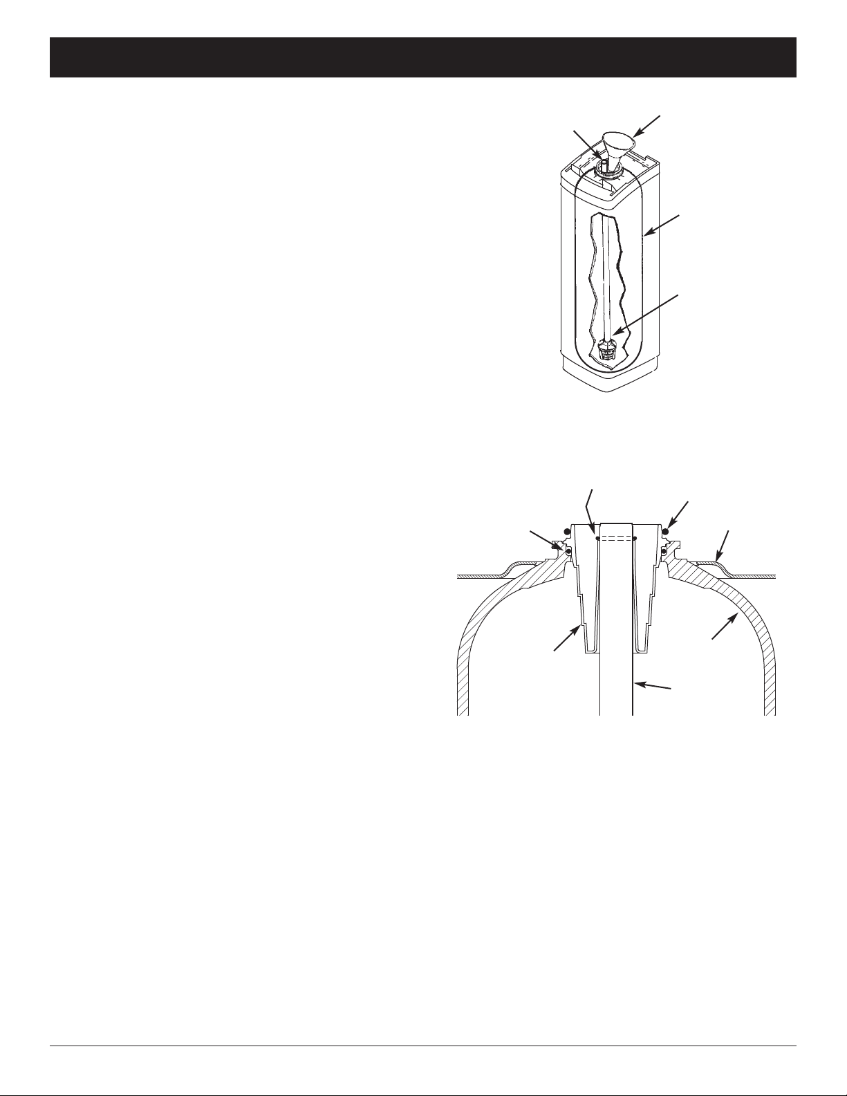
6. over the top end of the distributor riser pipe with a
clean rag, to keep gravel and media out (See Fig. 4).
7. Using a larger neck funnel, add the gravel (if used)
and media in that order. Be sure the distributor
remains centered. Use water sparingly to speed
flow through the funnel (It may become necessary
to siphon water from the bottom of distributor if
tank becomes full of water).
8. Flush the tank opening with water to clean media
particles from the top of the tank. Uncover the bot-
tom distributor riser pipe.
9. Finish filling the tank with water, up to the top of
the tank.
IMPORTANT: Be sure to fill with water. This will elim-
inate air space and prevent excessive
air-head pressure when tank is pres-
surized.
10. Install the o-ring seals and top distributor exactly
as shown in Figure 5. If the o-rings need lubrica-
tion, use a high quality silicone grease.
11. Lower the valve assembly onto the tank, centering
over the riser tube. Push downward, against the
o-ring, and install the clamp sections, securing
with the retainer clips.
12. Reconnect the wiring between the valve and the
control board (PWA).
FIG. 4
Funnel
Plug or cover top of
riser pipe
Tank
Make sure
bottom distributor
is centered
FIG. 5
Rim
Riser pipe
Top
Distributor
Tank
O-Ring,
2-7/8” x 3-1/4”
(thick)
O-Ring,
13/16” x 1-1/16”
O-Ring,
2-3/4” x 3”
(thin)

8
ECOWATER
SYSTEMS Typical Installation Illustrations
FIG. 6
Soft Water
OUT
INSTA ATION USING ECOWATER BYPASS VA VE
MAIN WATER PIPE
Hard Water
IN
INSTA ATION USING 3-VA VE BYPASS
MAIN WATER PIPE
BYPASS
Valve
OUTLET
Valve INLET
Valve
For soft water SERVI E:
-Open the inlet and outlet
valves
For hard water BYPASS:
- lose the inlet and outlet
valves
-Open the bypass valve
CROSS-OVER
Use if water supply flows from the left.
Include single or 3-valve bypass.
HARD
WATER
TO SOFTENER
INLET
SOFT
WATER
FROM SOFTENER
OUTLET
Hard Water
to Outside
Faucets
EcoWater
Bypass Valve
1-1/2”
Air Gap
1-1/2”
Air Gap
1-1/2” Air Gap
AUNDRY
TUB
SUMP
STAND
PIPE
To standpipe, sump, laundry tub or other suitable drain.
CONNECTING A RIGID VA VE DRAIN TUBE
ompression Fitting.
1/4 NPT x 1/2” O.D.
Tube (not included)
lip
Barbs
1/4 NPT
Threads
1/2” Outside Dia.
opper Tube
(not included)
ut barbs from drain fitting (pull
clip to remove fitting from valve)
1-1/2”
Air Gap
F OOR
DRAIN
Brine Tank
Overflow
Hose*
Secure Valve Drain Hose
in place over Floor Drain
Valve
Drain
Hose
*Do not connect the water
softener valve drain hose to
the brine tank overflow hose.
120V,
60 Hz
Outlet
IN ET
OUT ET
IN ET
OUT ET

9
ECOWATER
SYSTEMS Installation
1. TURN OFF WATER SUPP Y
a. lose the main water supply valve near the well
pump or water meter.
b. Shut off the electric or fuel supply to the water
heater.
c. Open high and low faucets to drain all water from
the house pipes.
2. INSTA BYPASS VA VE AND/OR
P ASTIC INSTA ATION ADAPTORS:
a. If installing a single bypass valve, push the bypass
valve, with lubricated o-ring seals in place, into the
valve inlet and outlet ports (See Figure 7).
- OR -
b. If installing a 3-valve bypass system, slide plastic
installation adaptors, with lubricated o-ring seals in
place, into the valve inlet and outlet ports, respec-
tively (See Figure 7).
c. If adding a turbine to the system, be sure the tur-
bine and support are in place in the valve outlet, as
shown in Figure 8.
d. Snap the two large plastic clips in place on the inlet
and outlet ports, from the top, down (See Figure 9).
Be sure they snap into place. Pull on the bypass
valve or installation adaptors, to make sure they
are held securely in place.
3. COMP ETE P UMBING TO AND FROM
THE SOFTENER
Using the “Typical Installation Illustration” on page 8
as a guide, observe all of the following cautions while
you connect inlet and outlet plumbing:
= Be sure incoming, hard water is directed to the
valve IN ET port.
= Be sure to install bypass valve(s).
= If making a soldered copper installation, do all
sweat soldering before connecting pipes to the fil-
ter fittings. Torch heat will damage plastic parts.
= Use pipe joint compound on all external pipe
threads.
= When turning threaded pipe fittings onto plastic fit-
tings, use care not to cross-thread.
= Support inlet and outlet plumbing in some manner
(use pipe hangers) to keep the weight off of the
valve fittings.
FIG. 9
O-ring lip
ross section of
valve inlet or outlet
Bypass valve or
installation adaptor
Snap clips into place between
larger diameter rings
FIG. 7
FIG. 8
*Turbine *Turbine Support Assembly
Valve Outlet
FIG. 10
Turn the bypass
valve downward if
connecting to floor
level plumbing
IN ET
OUT ET
IN ET
OUT ET
Plastic Installation
Adaptors
(install with lubricated
o-rings in softener valve
or bypass valve)
EcoWater
Bypass Valve
Lubricated
O-Rings
lips
lip
lip
*Turbine and support not included
10
ECOWATER
SYSTEMS Installation
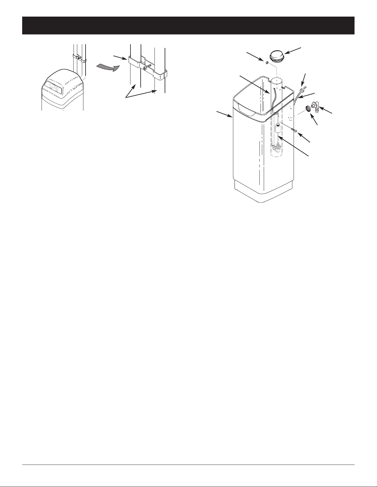
6. BRINE TANK ASSEMB Y
a. Position the brinewell in the recess at the bottom of
the brine tank and attach it to the side with the
screw and washer provided (See Figure 12).
b. Lower the brine valve into the brinewell until it is
sitting on the bottom. Route the brine tube out of
the brinewell through the top slot, and put the
brinewell cover into place (See Figure 12).
4. CO D WATER PIPE GROUNDING
The house cold water pipe (metal only) is often used
as a ground for the house electrical system. The 3-
valve bypass type of installation, shown in Figure 6,
will maintain ground continuity. If you use the plastic
bypass, continuity is broken. To restore the ground,
do either step 4a or 4b following.
a. Use the EcoWater ground clamp kit (not included)
to make a jumper across the inlet and outlet pipes
(See Figure 11).
b. Install a #4 copper wire across the removed sec-
tion of main water pipe, securely clamping at both
ends – parts not included.
5. INSTA VA VE DRAIN HOSE
a. Take a length of 1/2” inside diameter hose and
attach to the valve drain fitting, securing it with a
hose clamp (See Figure 6 on page 8).
b. Locate the other end of the hose at a suitable drain
point (floor drain, sump, laundry tub, etc.). heck
and comply with local codes. Refer to Figure 6 on
page 8 if codes require a rigid pipe drain run.
IMPORTANT: Use high quality, thick wall hose that
will not easily kink or collapse. The
softener will not backwash properly if
water cannot exit this hose during
recharges.
c. Tie or wire the hose in place at the drain point.
Water pressure will cause it to whip during the
backwash portion of the recharge cycle. Also pro-
vide an air gap of at least 1-1/2” between the end
of the hose and the drain point. An air gap pre-
vents possible siphoning of sewer water, into the
softener, if the sewer should back up.
d. If raising the drain hose overhead is required to get
to the drain point, do not raise higher than 8 feet
above the floor. Elevating the hose may cause a
back pressure that could reduce backwash flow
and proper resin bed cleaning.
FIG. 11
Ground
lamp
Inlet / Outlet
Pipes
7. INSTA BRINE TANK OVERF OW HOSE
This drain is for safety only. If the brine tank should
over-fill with water, the excess is carried to the drain.
a. Take the rubber grommet and hose adaptor elbow
from the parts bag. Push grommet into the corre-
sponding hole in the back wall of the brine tank.
Then insert the larger diameter end of the elbow
through the grommet.
b. Attach a length of 1/2” inside diameter hose to the
drain elbow, installed in the previous step. Use a
hose clamp to hold it in place.
c. Locate the other end of the hose at the drain point.
Do not elevate this hose higher than the elbow on
the brine tank. Do not tee this hose to the valve
drain hose.
FIG. 12
Brinewell over
Washer
Ferrule
Nut
Brine
Tank
Brinewell
Brine Tubing
Brine Valve
Screw
Grommet
Elbow

11
8. CONNECT BRINE TUBING
a. Route the brine tube out of the brine tank through
the smaller hole in the tank back wall.
b. onnect the brine tube to the nozzle/venturi
assembly using the ferrule nut provided (See
Figure 13).
9. PRESSURE TESTING FOR EAKS,
PROGRAMMING THE CONTRO ER &
RINSING THE MEDIA
To prevent excessive air pressure in the water
softener and plumbing system, do the following
steps EXACT Y in order:
a. Fully open two or more softened cold water
faucets nearby the water softener.
b. Place the bypass valve(s) in bypass position (See
Figures 2 & 6).
c. Fully open the main water supply valve. Watch
until the flow from the opened faucets becomes
steady, with no spurting or air bubbles.
d. After about three minutes, open a hot water faucet
for one minute, or until all air is expelled.
FIG. 13
1-1/2”
Air Gap
Ferrule Nut
Brine
Tubing
Floor Drain
Brine Tank
Overflow Hose
Valve
Drain Hose
ECOWATER
SYSTEMS Installation
e. lose all faucets and check your plumbing work for
leaks.
f. Make sure the softener’s valve drain hose is
hooked up and the open end directed to a floor
drain, laundry tub or other suitable type of drain.
g. Make sure the softener’s bypass valve is in the
bypass position.
h. Plug in the power supply.
i. Program the electronic controller: Follow the
steps on Pages 13 & 14 (for softeners) or Page 16
(for filters) to program the electronic controller with
basic operating information, such as time and water
hardness. After completing these steps, continue
with “j. Start a recharge”, below.
j. Start a recharge: Press the RE HARGE button
and hold for 3 seconds, until “Recharge Now” flash-
es in the display and you hear the valve motor run
as the softener begins recharging.
k. Once the unit is in backwash, place bypass
valve(s) into the service position, as follows:
(1) SINGLE BYPASS VALVE: Slowly move the
valve stem toward service position, pausing sev-
eral times to allow the unit to pressurize slowly.
(2) 3-VALVE BYPASS: Fully close the bypass
valve and open the outlet valve. Slowly open
the inlet valve, pausing several times to allow the
unit to pressurize slowly.
l. Let the softener complete the backwash and fast
rinse cycles (takes 10-12 minutes). When the
recharge cycle ends, the softener valve returns to
the service position.
10. ADD WATER AND SA T TO THE
BRINE TANK
a. Using a pail or garden hose, add about 3 gallons of
water into the brine tank. DO NOT pour into the
brinewell.
b. Add salt to the brine tank. It is recommended to fill
the brine tank no more than 1/2 full. Level the salt
when finished adding. You can use most water
softener salts, but it must be clean.
Recommended nugget, pellet or coarse solar salts
have less than 1% impurities.
NOTE: See page 20 for additional information on salt.

12
ECOWATER
SYSTEMS Installation & Sanitizing
11. SANITIZING THE WATER SOFTENER
are is taken at the factory to keep your EcoWater
Systems water softener clean and sanitary. However,
during shipping, storage, installing and operating,
bacteria could get into the unit. For this reason, sani-
tizing as follows is suggested* when installing.
a. Remove the brinewell cover and pour about 1-1/2
oz. (2 to 3 tablespoons) of common household
bleach into the softener’s brinewell. Replace the
brinewell cover.
b. Make sure the bypass valve is in the service posi-
tion.
c. Start a recharge: Press the RE HARGE button
and hold for 3 seconds, until “Recharge Now”
flashes in the display and you hear the valve motor
run as the softener begins recharging. This
recharge draws the sanitizing bleach into and
through the softener. Any air remaining in the unit
is purged to the drain.
d. After the recharge has completed, fully open a cold
water faucet, downstream from the softener, and
allow 50 gallons of water to pass through the sys-
tem. This should take at least 20 minutes. lose
the faucet.
12. RESTART THE WATER HEATER
Turn on the electric or fuel supply to the water heater,
and light the pilot, if applies.
NOTE: The water heater is filled with hard water and,
as hot water is used, it refills with softened water. In
a few days, the hot water will be fully conditioned. To
have fully conditioned hot water immediately, wait
until the recharge (Step 11) is complete, then drain
the water heater until water runs cold.
*Recommended by the Water Quality Association. On
some water supplies, the EcoWater Systems unit may need
periodic disinfecting.

13
ECOWATER
SYSTEMS Programming the Electronic Controller
FIG. 14
UP button
DOWN button
Display
RE HARGE button SELE T button
CONTRO ER SETTINGS REQUIRED
upon installation, and after an extended power outage.
When the power supply is plugged into the electrical
outlet, a model code (example: ST31) and a version
number (example: J3.8), are briefly shown in the dis-
play. For softener or tannin filter use, you must select
the correct model code, as shown below.
SET MODE CODE
1. Press and hold for 3 seconds the SELE T button,
until the display shows “000 - -“ (See Figure 15).
3. Press the áUP or âDOWN buttons to select
the correct model code for softener or tannin filter
use. See the table below.
FIG. 17
2. Press the áUP or âDOWN buttons to set the
present time. Up moves the display ahead; down
sets the time back. Be sure AM or PM is correct.
NOTE: Press buttons and quickly release to slowly
advance the display. Hold the buttons down
for fast advance.
3. When the correct time is displayed, press the
SELE T button, and the display will change to
show the “Hardness” screen.
continued on next page
4. With the correct model code displayed, press the
SELE T button to restart the controller. Follow the
programming steps below to set the timer for sof-
tener use. If you are using the unit as a tannin
filter, go to the programming steps on Page 16.
SET PRESENT TIME OF DAY
1. If the words “PRESENT TIME" do not show in the
display, press the SELE T button several times
until they do.
Model Code Amount of Resin Tank Size
ST31 1 cu. ft. 10” x 47”
ST39 1-1/4 cu. ft. 10” x 47”
STAn use for tannin filters
2. Press and hold for 3 seconds the SELE T button
once again until a model code appears in the dis-
play.
FIG. 15
FIG. 16

14
ECOWATER
SYSTEMS Programming the Electronic Controller (Softeners)
FIG. 18
FIG. 19
SET WATER HARDNESS NUMBER
1. If you completed the previous step, the word
“HARDNESS" should show in the display (See
Figure 18). Otherwise, press the SELE T button
several times until it does.
2. Press the áUP or âDOWN buttons to set the
value of your water’s hardness in grains per gallon
(gpg). Hardness level can be turned OFF by
pressing the âDOWN button below 1. This would
be chosen if you wished to have the softener
recharge at a specific number of days.
NOTE: If your water supply contains iron, compen-
sate for it by adding to the water hardness
number. For example, assume your water is
20 gpg hard and contains 2 ppm iron. Add 5
to the hardness number for each 1 ppm of
iron. In this example, you would use 30 for
your hardness number.
20 gpg hardness
2 ppm iron x 5 = 10 +10
(times) 30 HARDNESS NUMBER
2. When finished setting your water’s hardness num-
ber, press the SELE T button. If a hardness num-
ber is selected, the next setup screen to appear
will be “Set Number of People”. If “OFF” is select-
ed, the next setup screen to appear will be “Set
Days Between Recharges”.
SET NUMBER OF PEOP E
If a hardness level was set in the previous step, you
will set the Number of People in the household.
1. Press the áUP or âDOWN buttons to set the
number of people. The factory default is 4.
2. When the correct number of people is displayed,
press the SELE T button, and the display will
change to show the “Set Recharge Time” screen.
1. Press the áUP or âDOWN buttons to set the
number of days.
2. When the correct number of days is displayed,
press the SELE T button, and the display will
change to show the “Set Recharge Time” screen.
SET REGENERATION STARTING TIME
1. If you completed the previous steps, the words
“RE HARGE TIME" should show in the display
(See Figure 21). Otherwise, press the SELE T
button several times until they do.
2. The softener’s default regeneration start time is
2:00 AM. In most households this is a good time
for regeneration to start (takes about 2 hours)
because water is not being used. During regenera-
tion hard water is bypassed to house faucets. Use
the áUP or âDOWN buttons to adjust the
recharge start time in 1 hour increments.
3. When the desired regeneration time is displayed,
press the SELE T button, and the display will
change to show the normal run time display.
SET DAYS BETWEEN RECHARGES
If a hardness level was set to “OFF”, you must set the
Number of Days Between Recharges.
FIG. 20
FIG. 21
FIG. 22

15
ECOWATER
SYSTEMS Features / Options (Softeners)
FIG. 23
FIG. 25
SET CAPACITY
The electronic controller determines this number,
based on the initial timer programming.
Setting Softening
Capacity Salt Use Water Use
AP 1 Lowest Most
salt efficient
Regenerates
more often
AP 2 Medium Medium Medium
AP 3 Highest Uses
most salt
Regenerates
less often
3. Press the SELE T button several times to return
advance through the remaining screens and return
to the normal run (time of day) display.
If you want to change the capacity, do the following:
1. Press and hold for 3 seconds the SELE T button,
until the display shows “000 - -“.
2. Once in this display, press the SELE T button
once and “ AP” will show in the display.
3. Use the áUP button to change to a 24 hour clock
display.
4. Press the SELE T button several times to
advance through the remaining screens and return
to the normal operation (time of day) display.
5. To change back to a 12 hour clock, follow Steps 1
through 4, above, except use the âDOWN button
in Step 3.
ADJUST BACKWASH AND RINSE TIME
The timer can be changed to allow different back-
wash and fast rinse times, if so desired. Each of
these can be adjusted from 0 to 99 minutes.
1. Press and hold the SELE T button until “000 - -”
shows in the display.
2. Press the SELE T button four times and “bA-” will
appear in the display, followed by the current back-
wash time, in minutes, flashing.
3. Use the áUP or âDOWN buttons to set the
number of minutes desired for backwash.
4. Press the SELE T button again and “Fr-” will
appear in the display, followed by the current fast
rinse time, in minutes, flashing.
5. Use the áUP or âDOWN buttons to set the
number of minutes desired for fast rinse.
6. Press the SELE T button several times to return
advance through the remaining screens and return
to the normal run (time of day) display.
3. Press the áUP or âDOWN buttons to set the
capacity number.
4. Press the SELE T button several times to return
advance through the remaining screens and return
to the normal run (time of day) display.
VIEW DAYS TO RECHARGE
This view-only display shows the number of days the
softener will run before the next recharge. This dis-
play will not be available if Hardness was set to OFF
(as described on the previous page).
1. Press and hold the SELE T button, until the dis-
play shows “000 - -“.
2. Press the SELE T button twice and “Recharge”
will show in the display.
12 OR 24 HOUR C OCK
The timer has been factory preset to display a 12 hour
(AM/PM) clock. If you prefer, you may change this to
display a 24 hour clock.
1. Press and hold the SELE T button, until the dis-
play shows “000 - -“.
2. Press the SELE T button three times and “12 hr”
will flash in the display.
FIG. 24
FIG. 26

16
ECOWATER
SYSTEMS Programming the Electronic Controller (Filters)
2. Press the áUP or âDOWN buttons to set the
number of days.
3. When the correct number of days is displayed,
press the SELE T button, and the display will
change to show the “Set Recharge Time” screen.
SET REGENERATION STARTING TIME
1. If you completed the previous steps, the words
“RE HARGE TIME" should show in the display
(See Figure 29). Otherwise, press the SELE T
button several times until they do.
2. The filter’s default regeneration start time is 2:00
AM. In most households this is a good time for
regeneration to start because water is not being
used. During regeneration hard water is bypassed
to house faucets. Use the áUP or âDOWN but-
tons to adjust the recharge start time in 1 hour
increments.
3. When the desired regeneration time is displayed,
press the SELE T button, and the display will
change to show the normal run time display.
FIG. 27
2. Press the áUP or âDOWN buttons to set the
present time. Up moves the display ahead; down
sets the time back. Be sure AM or PM is correct.
3. When the correct time is displayed, press the
SELE T button, and the display will change to
show the “Recharge” screen.
SET DAYS BETWEEN RECHARGES
This setting is the number of days the filter will go
between recharges. The default setting is 2 days,
with a maximum setting of 99 days.
1. If you completed the previous steps, the words
“RE HARGE" and “day” should show in the dis-
play (See Figure 28). Otherwise, press the
SELE T button several times until they do.
Complete the following programming steps if you
set the model code to “STAn”, as described on
Page 13, to use the unit as a tannin filter.
SET PRESENT TIME OF DAY
1. If the words “PRESENT TIME" do not show in the
display, press the SELE T button several times
until they do.
FIG. 28
FIG. 30
FIG. 29
ECOWATER
SYSTEMS Features / Options (Filters)
ADJUSTAB E FI
1. Press and hold for 3 seconds the SELE T button,
until the display shows “000 - -“.
2. Once in this display, press the SELE T button
once and “F” will appear in the display, followed by
the current fill time, in minutes, flashing.
3. Press the áUP or âDOWN buttons to set the fill
time, from 0 to 99:59 minutes.
4. Press the SELE T button several times to return
advance through the remaining screens and return
to the normal run (time of day) display.
FIG. 31
continued on next page
17
ECOWATER
SYSTEMS Features / Options (Filters)
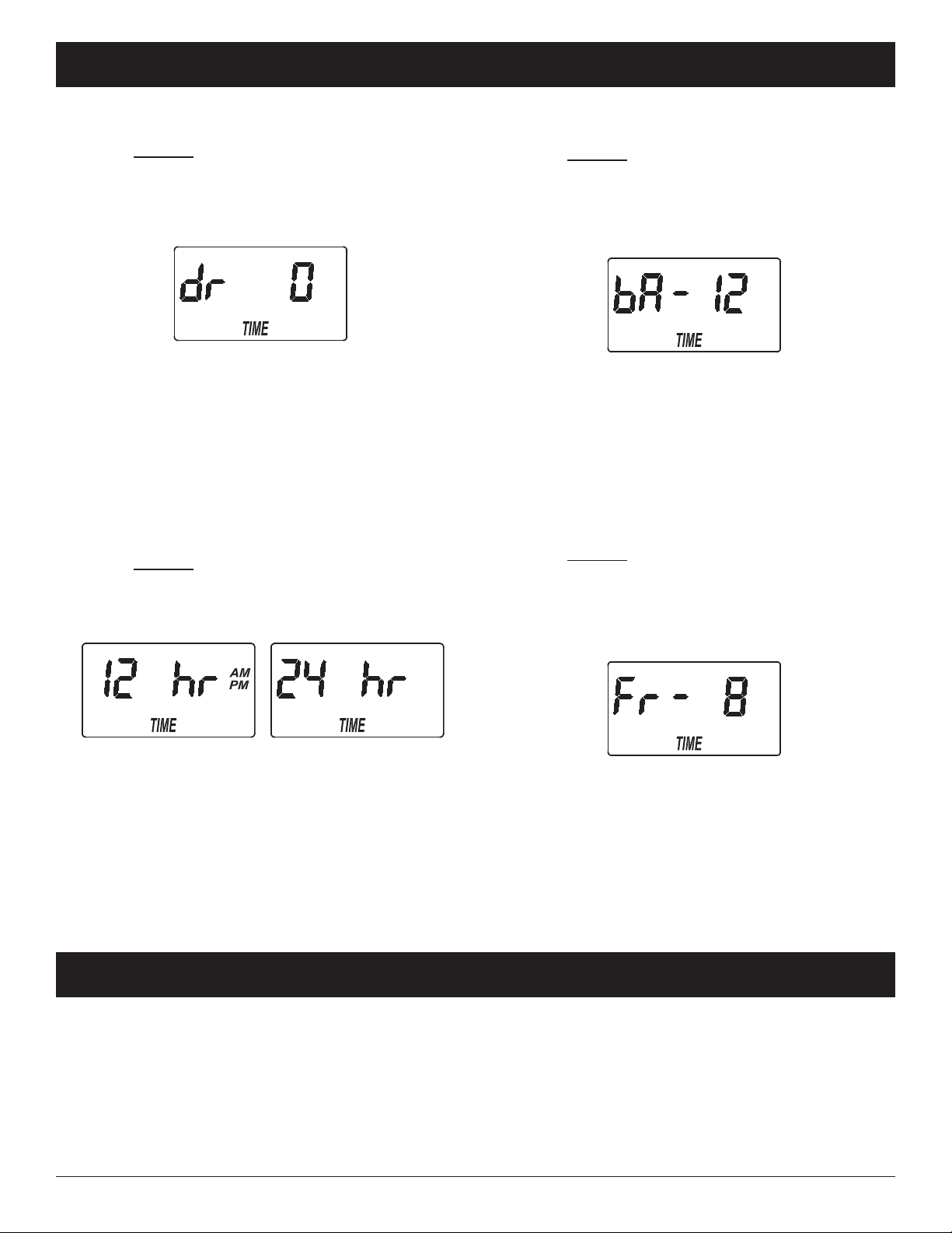
ADJUSTAB E BRINE DRAW
1. Press and hold the SELE T button, until the dis-
play shows “000 - -“.
2. Press the SELE T button twice and “dr” will
appear in the display, followed by the current brine
draw time, in minutes, flashing.
3. Press the áUP or âDOWN buttons to set the
brine draw time, from 0 to 255 minutes.
4. Press the SELE T button several times to return
advance through the remaining screens and return
to the normal run (time of day) display.
12 OR 24 HOUR C OCK
The timer has been factory preset to display a 12 hour
(AM/PM) clock. If you prefer, you may change this to
display a 24 hour clock.
1. Press and hold the SELE T button, until the dis-
play shows “000 - -“.
2. Press the SELE T button three times and “12 hr”
will flash in the display.
FIG. 32
ADJUSTAB E BACKWASH TIME
1. Press and hold the SELE T button until “000 - -”
shows in the display.
2. Press the SELE T button four times and “bA-” will
appear in the display, followed by the current back-
wash time, in minutes, flashing.
3. Use the áUP or âDOWN buttons to set the
number of minutes desired for backwash, from 0 to
99 minutes.
4. Press the SELE T button several times to return
advance through the remaining screens and return
to the normal run (time of day) display.
ADJUSTAB E FAST RINSE TIME
1. Press and hold the SELE T button until “000 - -”
shows in the display.
2. Press the SELE T button five times and “Fr-” will
appear in the display, followed by the current fast
rinse time, in minutes, flashing.
FIG. 34
FIG. 35
3. Use the áUP or âDOWN buttons to set the
number of minutes desired for fast rinse, from 0 to
99 minutes.
6. Press the SELE T button several times to return
advance through the remaining screens and return
to the normal run (time of day) display.
FIG. 33
3. Use the áUP button to change to a 24 hour clock
display.
4. Press the SELE T button several times to
advance through the remaining screens and return
to the normal operation (time of day) display.
5. To change back to a 12 hour clock, follow Steps 1
through 4, above, except use the âDOWN button
in Step 3.
ECOWATER
SYSTEMS Features / Options (All Models)
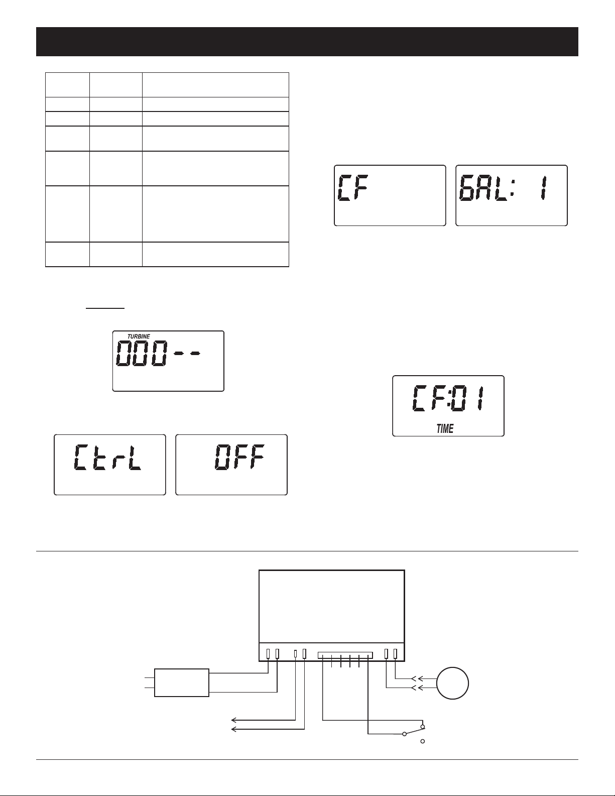
AUXI IARY OUTPUT CONTRO
The electronic controller’s auxiliary output may be
used to operate various types of external equipment,
such as a chlorine generator or chemical feeder. It
provides a 24V D , up to 500 mA, current from termi-
nal J4 on the electronic control board (see Schematic
on the next page). The table on the next page
explains the choices available for when the auxiliary
output will be on during various portions of the
recharge cycle.
continued on next page
18
5. CHEMICA FEEDER TIME: Use the áUP or
âDOWN buttons to set the length of time, in
seconds, that the auxiliary output will be turned on.
Then press the SELE T button to accept and
return to the normal run (time of day) screen.
ECOWATER
SYSTEMS Features / Options (Softeners & Filters)
SE EC-
TION NAME AUXI IARY OUTPUT
FUNCTION
OFF Off Remains off indefinitely.
BPBypass On during the entire recharge.
C hlorine On during the brine draw portion
of the recharge.
FS Flow
Switch
On when water is flowing past
the turbine*. It will shut off 8
seconds after water flow stops.
CF hemical
Feeder
After the set volume of water
has flowed past the turbine*,
turns on for the time set (see
Steps 4 & 5, below, to set vol-
ume and time).
FR Fast
Rinse
On during the fast rinse por-
tion of the recharge.
The default is OFF. If you wish to change to one of
the other selections shown in the table:
1. Press and hold the SELE T button until “000 - -”
shows in the display (See Figure 36).
3. Use the áUP or âDOWN buttons to display the
desired selection, then press the SELE T button.
If you selected anything other than F, the display
will return to the normal run (time of day) screen.
If setting to F ( hemical Feeder), there will be
two additional settings to make for operating the
chemical feeder in Steps 4 and 5, below.
FIG. 37
FIG. 38
FIG. 39
4. CHEMICA FEEDER TRIP VO UME: If you have
set the auxiliary output control to F ( hemical
Feeder), you will need to set the volume of water
which must flow past the turbine* before the auxil-
iary output is turned on. With the alternating
screens in Fig. 38 shown, use the áUP or
âDOWN buttons to set the trip volume, in gallons.
Then press the SELE T button to display the
screen shown in Fig. 39.
FIG. 36
2. Press the SELE T button several times, until “ trl"
flashes in the display (See Figure 37).
WIRING SCHEMATIC
FIG. 40
NO
Valve
Motor
Position
Switch
N
Power Supply
Back of Electronic ontroller
(PWA)
Power
In Pos./Turbine Motor
24V D
Auxiliary Output
J4
24V D
120V A
60 Hz
org
grn
*A turbine and turbine cable must be added to the system if auxiliary output selections “FS” or “ F” are to be used.

19
ECOWATER
SYSTEMS Features / Options (Softeners & Filters)
FIG. 41
RECHARGE NOW
For times when you expect to use more water than
usual, it may be desirable to perform a manually initi-
ated recharge. To manually start a recharge cycle,
press and hold the RE HARGE button for a few sec-
onds, until “RE HARGE NOW” flashes in the display.
FIG. 42
The softener/filter begins an immediate recharge.
Once started, you cannot cancel this recharge. Avoid
using hot water during this time, as the water heater
will refill with hard/unfiltered water.
VACATION MODE
Before going on vacation, or any other long absence,
press and release (do not hold) the RE HARGE but-
ton, so “VA ” begins flashing in the display.
In vacation mode the electronic controller continues to
keep time, but recharges will not occur using water
and salt.
When you return, press and release (do not hold) the
RE HARGE button to turn off the vacation mode and
return the softener/filter to normal operation. The
time of day screen (See Fig. 41) will then be dis-
played. Remember to do this, or the unit will not
recharge and you will soon have hard/unfiltered
water.
FIG. 43
NORMA OPERATION
During normal operation, the present time of day
shows in the display.
POWER OUTAGE MEMORY
If electrical power to the softener/filter’s control is lost,
internal memory will maintain most settings such as
the hardness and recharge time. However, unless
the power outage was very brief, the clock’s present
time will need to be reset. During a power outage,
the display will be blank and the unit will not
recharge. When electrical power is restored:
1. heck the display.
2a. If the present time is displayed steadily (not flash-
ing), the controller did not lose time and you do
not need to reset the clock.
2b. If a time is flashing in the display, then the clock
needs to be reset to the correct present time.
See “Set Present Time of Day” on page 13. The
flashing display is to remind you to reset the
clock. If you do not reset the clock, then
recharges will most likely occur at the wrong time
of day.
NOTE: If the unit was recharging when power was
lost, it will finish the cycle when power returns.
20
ECOWATER
SYSTEMS Routine Maintenance
REFI ING WITH SA T
If the softener uses all the salt before more is added,
hard water will result. Remove the brine tank lid and
check the salt level frequently. Until you have estab-
lished a refilling routine, check the salt every 2 or 3
weeks. Be sure that the brinewell cover is on when
adding salt.
NOTE: In humid areas it is best to keep the salt level
less than half full and refill more often.
RECOMMENDED SA T: ube, pellet, coarse solar,
etc., water softener salt is recommended. This type
of salt is high purity evaporated crystals, sometimes
formed and pressed into briquets. It has less than
1% insoluble (not dissolvable in water) impurities.
lean, high grade rock salts are acceptable, but may
require frequent brine tank cleaning to remove the
“sludge” residue (insolubles) collecting at the bottom
of the tank.
POTASSIUM CH ORIDE: If you choose potassium
chloride (K l) salt instead of standard sodium chlo-
ride (Na l) water softener salt as a regenerant:
1) The hardness setting must be increased by 25%.
2) Place only one bag of potassium chloride (K l) into
your water softener at a time. The salt storage
tank should never contain more than 60 pounds of
K l.
SA T NOT RECOMMENDED: Rock salt high in
impurities, block, granulated, table, ice melting, or ice
cream making salts, etc., are not recommended.
SA T WITH IRON REMOVING ADDITIVE: Some
salts have an additive to help a water softener handle
iron in the water supply. Although this may help keep
the resin bed clean, it may also release corrosive
fumes that will weaken and shorten the life of some
EcoWater Systems softener electronic parts. Iron Out
salt is safe to use on two-tank models.
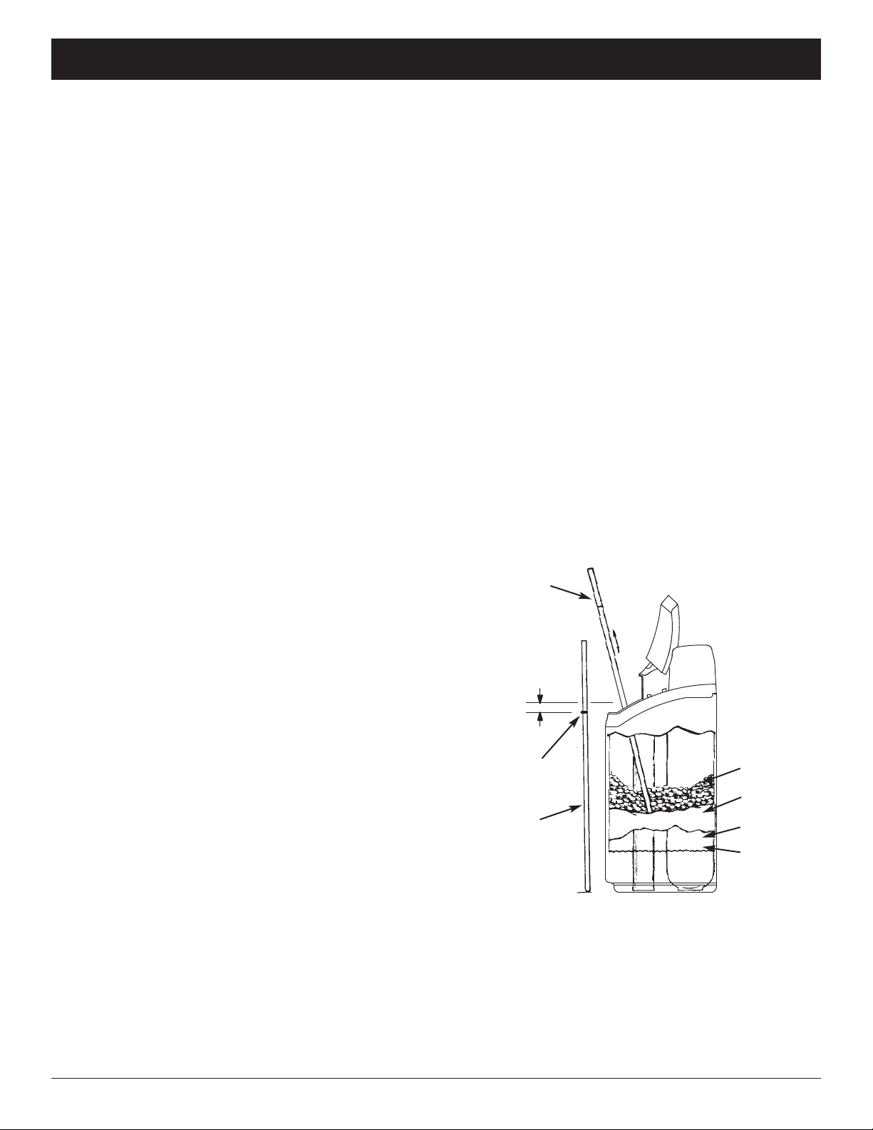
BREAKING A SA T BRIDGE
Sometimes a hard crust or salt “bridge” forms in the
brine tank. This is usually caused by high humidity or
the wrong kind of salt. When the salt bridges, an
empty space forms between the water and the salt.
Then salt will not dissolve in the water to make brine.
Without brine, the resin bed is not recharged and
hard water will result.
If the storage tank is full of salt, it is difficult to tell
whether there is a salt bridge. A bridge may be
underneath loose salt. The following is the best way
to check for a salt bridge:
Salt should be loose all the way to the bottom of the
tank. Hold a broom handle, or like tool, up to the
softener’s brine tank, as shown in Figure 44. Make a
pencil mark on the handle 1” - 2” below the top of the
rim. Then, carefully push it straight down into the
salt. If a hard object is felt before the pencil mark is
even with the top, it is most likely a salt bridge.
arefully push into the bridge in several places to
break it. Do not try to break the salt bridge by
pounding on the outside of the salt tank. You
may damage the tank.
FIG. 44
1” - 2”
Pencil Mark
Broom
Handle
Push tool into
salt bridge
to break
Water Level
Empty Space
Salt Bridge
Salt
Table of contents
Other EcoWater Lawn And Garden Equipment manuals

Popular Lawn And Garden Equipment manuals by other brands


CPE
CPE 50075 Owner's manual & operating instructions

Land Pride
Land Pride REAR BLADES RBT55120 Operator's manual

EMAK
EMAK Oleo-Mac MH 175 RK owner's manual

Everbloom
Everbloom Two Tiers Raised Garden Bed installation guide

Retractable Awnings
Retractable Awnings Hamburg installation instructions

Rowenta
Rowenta Mosquito Protect MN4010 manual


