Cramer A48T10E-CR User manual

P0803826-00
P0803826-00
技术要求:
2.120P, 内容见电子档;
3.单黑印刷,保持色块始终朝外,要求无色差、无污点;
4.胶装,裁切均匀、无连页;
5.以封样为准。
6.料件需符合格力博HSF文件(编号:GLB-CGR-146) 里关于环保和有害物质的具体要求。
1.材质要求:封面封底120g双胶纸(4P),内页60g双胶纸(116P),85%本白;
常州格力博集团
说明书
杨媛
周艳
王小妮
李海平
21.10.8
A B
B
版本号
重要度等级
日 期
工艺
审核
校对
设计
标记处数 签名 日期
阶段标记 视角标记 重量 比例
批准
审定
标准化
日期
更改文件号
SCALE: A5
210mm
145mm
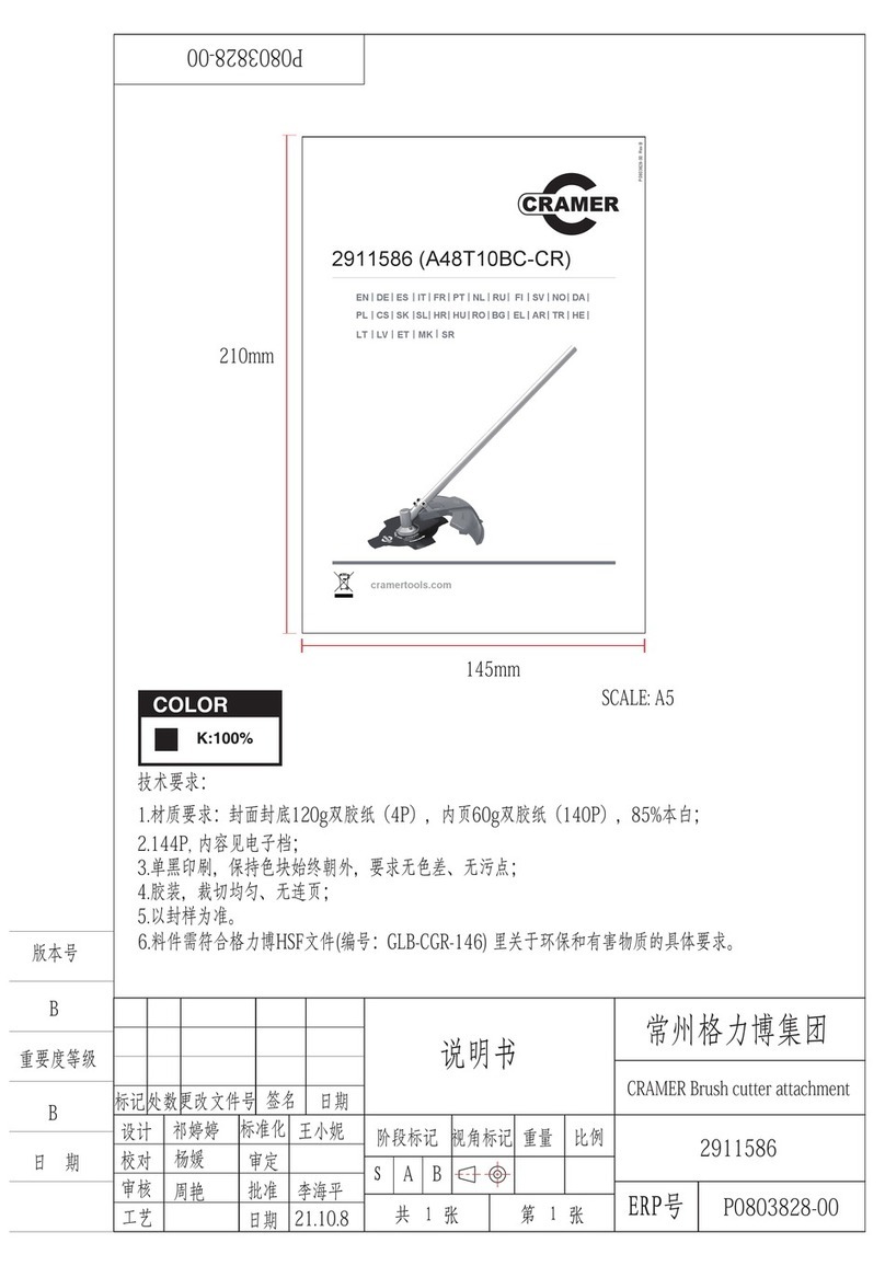
CRAMER Edger attachment
2911486
B祁婷婷
EN | DE | ES | IT | FR | PT | NL | RU | FI || SV |
| NO|
| DA |
PL | CS | SK |
SL| HR| HU | RO | BG | EL || AR |
| TR |
| HE |
LT | LV | ET |
2911486 (A48T10E-CR)
cramertools.com
BveR
00-6283080P
MK | SR

EN | DE | ES | IT | FR | PT | NL | RU | FI || SV |
| NO|
| DA |
PL | CS | SK |
SL| HR | HU | RO | BG | EL || AR |
| TR |
| HE |
LT | LV | ET |
2911486 (A48T10E-CR)
cramertools.com
BveR
00-6283080P
MK | SR


1 Description.........................................4
1.1 Purpose.............................................................. 4
1.2 Overview........................................................... 4
2 Safety.................................................. 4
3 Installation......................................... 4
3.1 Unpack the machine.......................................... 4
3.2 Assemble the shaft.............................................4
4 Operation........................................... 4
4.1 Adjust the depth of cut.......................................4
4.2 Operation tips.................................................... 4
5 Maintenance.......................................5
5.1 General information...........................................5
5.2 Clean the machine............................................. 5
5.3 Replace the blade...............................................5
5.4 Replace the skid plate........................................5
5.5 Replace the wheel..............................................5
6 Transportation and storage..............5
6.1 Store the machine.............................................. 5
7 Troubleshooting.................................6
8 Technical data....................................6
3
English EN

1 DESCRIPTION
1.1 PURPOSE
This edger is used to trim and cut around the edge of
driveways, side walks and more. The edger is not meant to be
used to cut hedges, shrubs, bushes, or flowers.
1.2 OVERVIEW
Figure 1 - 9.
1Edger attachment
2Guard
3Blade
4Wheel
5Depth adjustment knob
6Release button
7Position hole
8Coupler
9Knob
10 Nut
11 Outer cup
12 Plate
13 Metal rod
14 Skid plate
15 Washer
16 Axle sleeve
17 Wheel axle
2 SAFETY
WARNING
Make sure that you follow all safety instructions.
Refer to Safety Manual.
3 INSTALLATION
3.1 UNPACK THE MACHINE
WARNING
Make sure that you correctly assemble the machine before
use.
WARNING
• If parts of the machine are damaged, do not use the
machine.
• If you do not have all the parts, do not operate the
machine.
• If parts are damaged or missing, contact the service
center.
1. Open the package.
2. Read the documentation provided in the box.
3. Remove all the unassembled parts from the box.
4. Remove the machine from the box.
5. Discard the box and packing material in compliance with
local regulations.
3.2 ASSEMBLE THE SHAFT
Figure 2.
1. Loosen the knob on the coupler.
2. Push in the release button on the lower shaft.
3. Align the release button with the positioning hole and
move the two shafts towards each other.
4. Turn the lower shaft until the button locks into the
positioning hole.
5. Tighten the knob.
4 OPERATION
IMPORTANT
Before you operate the machine, read and understand the
safety regulations and the operation instructions.
WARNING
Be careful when you operate the machine.
4.1 ADJUST THE DEPTH OF CUT
Figure 3 - 4.
1. Remove the battery pack.
2. Loosen the depth adjustment knob to increase or decrease
the depth.
3. Adjust the depth so that the blade barely touches the
ground when the machine is held in a normal operating
posture.
4. Tighten the depth adjustment knob.
5. Standing in a normal working position, check the depth of
cut again and correct if necessary.
6. Replace the battery pack once all adjustments are
complete.
4.2 OPERATION TIPS
Figure 9.
WARNING
Always hold the edger away from the body keeping
clearance between your body and the edger. Any contact
with the edger cutting head while operating can result in
serious personal injury.
• Hold the edger with your right hand on the rear handle
and your left hand on the front handle.
4
English
EN

• Keep a firm grip with both hands while in operation.
• Edger should be held at a comfortable position with the
rear handle about hip height.
• The edger will edge along sidewalks, driveways, flower
beds, curbs, and similar areas.
• Cut at a steady pace. If the blade begins to bog down, you
are edging too fast; slow your pace. Do not force the
blade into ground.
• Light contact of the blade against the sidewalk edge,
curb, etc., is acceptable and will not damage the edger.
• Best appearance is obtained when grass is dry. Avoid
edging in wet soil or wet grass areas or the blade guard
might clog and result in an uneven edge. If the blade
guard becomes clogged, stop the edger, remove the
battery, and remove debris from the blade guard.
5 MAINTENANCE
IMPORTANT
Read and understand the safety regulations and the
maintenance instructions before you clean, repair or do the
maintenance work on the machine.
IMPORTANT
Make sure that all nuts, bolts and screws are tight. Check
regularly that the handles are firmly mounted.
IMPORTANT
Use only the replacement parts and accessories of the initial
manufacturer.
5.1 GENERAL INFORMATION
IMPORTANT
Only your dealer or approved service center can do the
maintenance that is not given in this manual.
Before the maintenance operations:
• Stop the machine.
• Remove the battery pack.
• Cool the motor.
• Store the machine in a cool and dry place.
• Use correct clothing, protective gloves and safety glasses.
5.2 CLEAN THE MACHINE
• Clean the machine after use with a moist cloth dipped in
neutral detergent.
• Do not use aggressive detergents or solvents to clean the
plastic parts or handles.
• Keep the trimmer head free of grass, leaves, or excessive
grease.
• Keep the air vents clean and free of debris to avoid
overheating and damage to the motor or the battery.
• Do not spray water onto the motor and electrical
components.
5.3 REPLACE THE BLADE
Figure 5 - 6.
NOTE
If the blade worn out, replace it with a new one (not
provided).
1. Use a metal rod to fix the blade.
2. Remove the nut by turning it clockwise with the wrench
(not included).
3. Remove the outer cup and the plate.
4. Remove the old blade and replace it with a new one.
5. Place the plate and outer cup on the blade.
6. Place the nut on the plate and tighten it counterclockwise
with the wrench.
5.4 REPLACE THE SKID PLATE
Figure 7.
1. Remove the screws with a Phillips Head screwdriver (not
included).
2. Replace with the new skid plate.
3. Tighten the screws.
5.5 REPLACE THE WHEEL
Figure 8.
1. Remove the battery.
2. Remove the knob, washer, wheel, axle sleeve, washer and
wheel axle orderly from the wheel assembly.
3. Replace with the new wheel.
4. Insert the wheel axle through the slot downward, then put
the washer, axle sleeve , wheel, washer and knob orderly
through the wheel axle.
5. Tighten the knob.
6 TRANSPORTATION AND
STORAGE
WARNING
Remove the battery pack from the machine before
transportation and storage.
6.1 STORE THE MACHINE
• Remove the battery pack from the machine.
• Make sure that children cannot come near the machine.
• Keep the machine away from corrosive agents such as
garden chemicals and de-icing salts.
5
English EN

• Secure the machine during transportion to prevent
damage or injury. Clean and examine the machine for any
damage.
7 TROUBLESHOOTING
Problem Possible Cause Solution
The ma-
chine does
not start
when you
push the
trigger.
No electrical con-
tact between the
machine and the
battery pack.
1. Remove battery pack.
2. Check contact and in-
stall the battery pack
again.
The battery pack is
depleted.
Charge the battery pack.
The lock-out but-
ton and trigger are
not pushed at the
same time.
1. Pull the lock-out but-
ton and hold it.
2. Pull the trigger to start
the machine.
Edger stops
during use.
Depth is set too
low.
Adjust the depth as
shown in the instrustion
manual.
Walking too fast. Do not force the edger
through the grass.
8 TECHNICAL DATA
Cutting head Blade
Blade length 225mm
Weight 1.9 kg
6
English
EN

1 Beschreibung......................................8
1.1 Verwendungszweck........................................... 8
1.2 Übersicht............................................................8
2 Sicherheit........................................... 8
3 Montage..............................................8
3.1 Maschine auspacken..........................................8
3.2 Montieren des Schafts....................................... 8
4 Bedienung...........................................8
4.1 Schnitttiefe einstellen........................................ 8
4.2 Tipps zur Bedienung..........................................9
5 Wartung und Instandhaltung...........9
5.1 Allgemeine Informationen.................................9
5.2 Maschine reinigen..............................................9
5.3 Messer ersetzen..................................................9
5.4 Kufenblech ersetzen.......................................... 9
5.5 Rad ersetzen.....................................................10
6 Transport und Lagerung................ 10
6.1 Maschine lagern...............................................10
7 Fehlerbehebung...............................10
8 Technische Daten.............................10
7
Deutsch
DE

1 BESCHREIBUNG
1.1 VERWENDUNGSZWECK
Dieser Kantenschneider wird zum Zurückschneiden und
Schneiden der begrünten Ränder von Einfahrten,
Seitenwegen etc. verwendet. Der Kantenschneider ist nicht
zum Schneiden von Hecken, Sträuchern, Büschen oder
Blumen geeignet.
1.2 ÜBERSICHT
Abbildung 1 - 9.
1Kantenschneideraufsatz
2Schutzabdeckung
3Messer
4Rad
5Tiefenverstellknauf
6Entriegelungstaste
7Positionierungsbohrung
8Verbindungsstück
9Handgriff
10 Mutter
11 Äußere Abdeckung
12 Scheibe
13 Metallstange
14 Kufenblech
15 Unterlegscheibe
16 Achsbuchse
17 Radachse
2 SICHERHEIT
WARNUNG
Stellen Sie sicher, dass Sie alle Sicherheitshinweise
befolgen.
Siehe Sicherheitshandbuch.
3 MONTAGE
3.1 MASCHINE AUSPACKEN
WARNUNG
Vergewissern Sie sich, dass Sie die Maschine vor dem
Gebrauch richtig montiert haben.
WARNUNG
• Bei beschädigten Maschinenteilen dürfen Sie die
Maschine nicht verwenden.
• Wenn Sie nicht alle Teile haben, dürfen Sie die
Maschine nicht in Betrieb nehmen.
• Wenn Teile beschädigt sind oder fehlen, wenden Sie
sich an die Servicestelle.
1. Öffnen Sie die Verpackung.
2. Lesen Sie die beiliegende Dokumentation.
3. Entnehmen Sie alle unmontierten Teile aus dem Karton.
4. Nehmen Sie die Maschine aus dem Karton.
5. Entsorgen Sie den Karton und das Verpackungsmaterial
gemäß den örtlichen Vorschriften.
3.2 MONTIEREN DES SCHAFTS
Abbildung 2.
1. Lösen Sie den Knauf am Verbindungsstück.
2. Drücken Sie die Entriegelungstaste am unteren Schaft.
3. Richten Sie die Entriegelungstaste auf die
Positionierungsbohrung aus und bewegen Sie die beiden
Schaftteile aufeinander zu.
4. Drehen Sie den unteren Schaft, bis die Taste in der
Positionierungsbohrung einrastet.
5. Ziehen Sie den Knauf fest.
4 BEDIENUNG
WICHTIG
Bevor Sie die Maschine in Betrieb nehmen, lesen und
verstehen Sie die Sicherheitsvorschriften und die
Bedienungsanleitung.
WARNUNG
Seien Sie vorsichtig, wenn Sie die Maschine bedienen.
4.1 SCHNITTTIEFE EINSTELLEN
Abbildung 3 - 4.
1. Entfernen Sie den Akkupack.
2. Lösen Sie den Tiefenverstellknauf, um die Schnitttiefe zu
erhöhen oder zu verringern.
3. Stellen Sie die Schnitttiefe so ein, dass das Messer den
Boden kaum berührt, wenn die Maschine in der normalen
Betriebshaltung gehalten wird.
4. Ziehen Sie Tiefenverstellknauf fest.
5. Überprüfen Sie die Schnitttiefe in normaler
Arbeitsposition und korrigieren Sie diese gegebenenfalls.
6. Wenn alle Einstellungen abgeschlossen sind, setzen Sie
den Akkupack wieder ein.
8
Deutsch
DE

4.2 TIPPS ZUR BEDIENUNG
Abbildung 9.
WARNUNG
Halten Sie den Kantenschneider immer von ihrem Körper
fern und wahren Sie einen gewissen Sicherheitsabstand
zwischen Ihrem Körper und dem Kantenschneider.
Während des Kantenschneiderbetriebs kann jeder Kontakt
mit dem Schneidkopf zu schweren Verletzungen führen.
• Halten Sie den Kantenschneider mit der rechten Hand am
hinteren Griff und mit der linken Hand am Frontgriff.
• Halten Sie das Gerät während des Betriebs fest in beiden
Händen.
• Der Kantenschneider sollte in einer bequemen Position
gehalten werden, wobei sich der hintere Griff etwa auf
Hüfthöhe befinden sollte.
• Der Kantenschneider wird entlang von Gehwegen,
Einfahrten, Blumenbeeten, Bordsteinen und ähnlichen
Bereichen eingesetzt.
• Schneiden Sie in gleichmäßigem Tempo. Wenn das
Messer zu stocken beginnt, sind Sie zu schnell unterwegs;
verlangsamen Sie Ihr Tempo. Drücken Sie das Messer
nicht mit Gewalt in den Boden.
• Leichter Messerkontakt mit der Gehwegkante, dem
Bordstein usw. ist akzeptabel und beschädigt den
Kantenschneider nicht.
• Das beste Ergebnis wird bei trockenem Gras erreicht.
Vermeiden Sie es, die Kanten bei nassem Boden oder
nassem Gras zu schneiden, da sich der Messerschutz
zusetzen kann und dann zu einer ungleichmäßigen Kante
führt. Wenn sich der Messerschutz zugesetzt hat, schalten
Sie den Kantenschneider aus, nehmen Sie den Akkupack
heraus und säubern Sie den Messerschutz.
5 WARTUNG UND
INSTANDHALTUNG
WICHTIG
Lesen und verstehen Sie die Sicherheitsvorschriften und die
Wartungsanweisungen, bevor Sie die Maschine reinigen,
reparieren oder die Wartungsarbeiten durchführen.
WICHTIG
Achten Sie darauf, dass alle Muttern, Schrauben und Bolzen
fest angezogen sind. Überprüfen Sie regelmäßig, ob Sie die
Griffe fest montiert haben.
WICHTIG
Verwenden Sie nur die Ersatz- und Zubehörteile des
Herstellers.
5.1 ALLGEMEINE INFORMATIONEN
WICHTIG
Nur Ihr Händler oder eine zugelassene Servicestelle kann
die Wartung durchführen, die nicht in diesem Handbuch
beschrieben ist.
Vor den Wartungsarbeiten:
• Stoppen Sie die Maschine.
• Entfernen Sie den Akkupack.
• Lassen Sie den Motor abkühlen.
• Lagern Sie die Maschine kühl und trocken.
• Korrekte Kleidung, Schutzhandschuhe und Schutzbrille
tragen.
5.2 MASCHINE REINIGEN
• Reinigen Sie die Maschine nach Gebrauch mit einem
feuchten Tuch, das mit neutralem Reinigungsmittel
befeuchtet ist.
• Verwenden Sie keine aggressiven Reinigungs- oder
Lösungsmittel zur Reinigung der Kunststoffteile oder
Griffe.
• Halten Sie den Schneidkopf frei von Gras, Laub oder
übermäßigem Fett.
• Halten Sie die Lüftungsöffnungen sauber und frei von
Schmutz, um Überhitzung und Schäden am Motor oder
an der Batterie zu vermeiden.
• Sprühen Sie kein Wasser auf den Motor und die
elektrischen Komponenten.
5.3 MESSER ERSETZEN
Abbildung 5 - 6.
HINWEIS
Wenn sich das Messer abgenutzt hat, ersetzen Sie es durch
ein neues (nicht mitgeliefert).
1. Verwenden Sie eine Metallstange, um das Messer zu
befestigen.
2. Entfernen Sie die Mutter, indem Sie sie mit dem
Schraubenschlüssel (nicht im Lieferumfang enthalten) im
Uhrzeigersinn drehen.
3. Entfernen Sie die äußere Abdeckung und die Platte.
4. Entfernen Sie das alte Messer und ersetzen Sie es durch
ein neues.
5. Setzen Sie die Platte und die äußere Abdeckung auf das
Messer.
6. Setzen Sie die Mutter auf die Platte und ziehen Sie sie mit
dem Schraubenschlüssel fest gegen den Uhrzeigersinn an.
5.4 KUFENBLECH ERSETZEN
Abbildung 7.
9
Deutsch
DE

1. Entfernen Sie die Schrauben mit einem
Kreuzschlitzschraubendreher (nicht im Lieferumfang
enthalten).
2. Tauschen Sie das neue Kufenblech ein.
3. Ziehen Sie die Schrauben an.
5.5 RAD ERSETZEN
Abbildung 8.
1. Entfernen Sie den Akkupack.
2. Entfernen Sie den Knauf, die Unterlegscheibe, das Rad,
die Achsbuchse, die Unterlegscheibe und die Radachse
nacheinander von der Radbaugruppe.
3. Tauschen Sie ein neues Rad ein.
4. Führen Sie die Radachse durch den Schlitz nach unten
und stecken Sie dann die Unterlegscheibe, die
Achsbuchse, das Rad, die Unterlegscheibe und den Knauf
der Reihe nach durch die Radachse.
5. Ziehen Sie den Knauf fest.
6 TRANSPORT UND LAGERUNG
WARNUNG
Nehmen Sie den Akkupack vor Transport und Lagerung aus
der Maschine.
6.1 MASCHINE LAGERN
• Nehmen Sie den Akkupack aus der Maschine.
• Stellen Sie sicher, dass Kinder nicht in die Nähe der
Maschine kommen können.
• Halten Sie die Maschine von aggressiven Mitteln wie
Gartenchemikalien und Auftausalzen fern.
• Sichern Sie die Maschine während des Transports, um
Schäden oder Verletzungen zu vermeiden. Reinigen und
prüfen Sie die Maschine auf Beschädigungen.
7 FEHLERBEHEBUNG
Problem Mögliche
Ursache
Lösung
Die Ma-
schine star-
tet nicht,
wenn Sie
den Auslös-
er drücken.
Kein elektrischer
Kontakt zwischen
der Maschine und
dem Akkupack.
1. Entfernen Sie den Ak-
kupack.
2. Überprüfen Sie den
Kontakt und setzen Sie
den Akkupack wieder
ein.
Der Akkupack ist
leer.
Laden Sie den Akkupack
auf.
Die Sperrtaste und
der Auslöser wer-
den nicht gleich-
zeitig gedrückt.
1. Ziehen Sie die Sperr-
taste und halten Sie sie
gedrückt.
2. Ziehen Sie den Auslös-
er, um die Maschine zu
starten.
Kantensch-
neider
bremst im
Einsatz ab.
Die Schnitttiefe ist
zu niedrig einges-
tellt.
Stellen Sie die Tiefe ein,
wie in der Bedienungsan-
leitung angegeben.
Sie laufen zu
schnell.
Schieben Sie den Kant-
enschneider nicht mit Ge-
walt durch das Gras.
8 TECHNISCHE DATEN
Schneidkopf Messer
Klingenlänge 225 mm
Gewicht 1.9 kg
10
Deutsch
DE

1 Descripción.......................................12
1.1 Finalidad.......................................................... 12
1.2 Perspectiva general..........................................12
2 Seguridad......................................... 12
3 Instalación........................................12
3.1 Desembalaje de la máquina............................. 12
3.2 Montaje del eje................................................ 12
4 Funcionamiento...............................12
4.1 Ajuste de la profundidad de corte....................12
4.2 Consejos de funcionamiento............................12
5 Mantenimiento.................................13
5.1 Información general.........................................13
5.2 Limpieza de la máquina...................................13
5.3 Sustitución de la cuchilla.................................13
5.4 Sustitución de la placa de protección de
bajos.................................................................13
5.5 Sustitución de la rueda.....................................13
6 Transporte y almacenamiento........14
6.1 Almacenamiento de la máquina...................... 14
7 Solución de problemas.................... 14
8 Datos técnicos.................................. 14
11
Español
ES

1 DESCRIPCIÓN
1.1 FINALIDAD
Esta bordeadora se utiliza para recortar y cortar alrededor del
borde de calzadas, aceras y más. La bordeadora no se ha
diseñado para cortar setos, arbustos, matorrales o flores.
1.2 PERSPECTIVA GENERAL
Figura 1 - 9.
1Accesorio bordeador
2Protección
3Cuchilla
4Rueda
5Mando de ajuste de profundidad
6Botón de desbloqueo
7Orificio de posicionamiento
8Acoplamiento
9Mando
10 Tuerca
11 Copa exterior
12 Placa
13 Varilla metálica
14 Placa de protección de bajos
15 Arandela
16 Manguito del eje
17 Eje de rueda
2 SEGURIDAD
AVISO
Asegúrese de seguir todas las instrucciones de seguridad.
Consulte el manual de seguridad.
3 INSTALACIÓN
3.1 DESEMBALAJE DE LA MÁQUINA
AVISO
Asegúrese de montar correctamente la máquina antes del
uso.
AVISO
• Si las piezas de la máquina presentan daños, no utilice
la máquina.
• Si no tiene todas las piezas, no utilice la máquina.
• Si faltan piezas o hay piezas dañadas, contacte con el
centro de servicio.
1. Abra el embalaje.
2. Lea la documentación que se proporciona en la caja.
3. Retire todas las piezas sin montar de la caja.
4. Retire la máquina de la caja.
5. Deseche la caja y el material de embalaje de conformidad
con los reglamentos locales.
3.2 MONTAJE DEL EJE
Figura 2.
1. Afloje el mando del acoplamiento.
2. Pulse el botón de desbloqueo del eje inferior.
3. Alinee el botón de desbloqueo con el orificio de
posicionamiento y mueva los dos ejes para acercarlos.
4. Gire el eje inferior hasta que el botón se bloquee en el
orificio de posicionamiento.
5. Apriete el mando.
4 FUNCIONAMIENTO
IMPORTANTE
Antes de utilizar la máquina, debe leer y entender las
normas de seguridad y las instrucciones de funcionamiento.
AVISO
Tenga cuidado cuando utilice la máquina.
4.1 AJUSTE DE LA PROFUNDIDAD DE
CORTE
Figura 3 - 4.
1. Retire la batería.
2. Afloje el mando de ajuste de profundidad para aumentar
o disminuir la profundidad.
3. Ajuste la profundidad de modo que la cuchilla apenas
toque el suelo cuando la máquina se mantiene en una
posición de funcionamiento normal.
4. Apriete el mando de ajuste de profundidad.
5. De pie en una posición de trabajo normal, compruebe
nuevamente la profundidad de corte y corríjala en caso
necesario.
6. Vuelva a colocar la batería una vez que todos los ajustes
hayan finalizado.
4.2 CONSEJOS DE
FUNCIONAMIENTO
Figura 9.
12
Español
ES

AVISO
Mantenga siempre la bordeadora alejada del cuerpo
manteniendo un espacio entre su cuerpo y la bordeadora.
Cualquier contacto con el cabezal de corte de la bordeadora
durante el funcionamiento puede provocar lesiones
personales graves.
• Sujete la bordeadora con la mano derecha en el asa
posterior y la mano izquierda en el asa delantera.
• Mantenga un agarre firme con ambas manos durante el
funcionamiento.
• La bordeadora debe mantenerse en una posición cómoda
con el asa posterior a la altura de la cadera.
• La bordeadora cortará los bordes a lo largo de aceras,
calzadas, macizos de flores, bordillos y zonas similares.
• Corte a un ritmo uniforme. Si la cuchilla empieza a
atascarse, está bordeando demasiado rápido; ralentice su
ritmo. No fuerce la cuchilla en el suelo.
• El contacto ligero de la cuchilla contra el borde de la
acera, el bordillo, etc., es aceptable y no dañará la
bordeadora.
• La mejor apariencia se obtiene cuando la hierba está seca.
Evite bordear en el suelo húmedo o en zonas húmedas de
césped, ya que la protección de la cuchilla podría
obstruirse y producir un borde desigual. Si el protector de
la cuchilla se obstruye, detenga la bordeadora, retire la
batería y retire los residuos del protector de la cuchilla.
5 MANTENIMIENTO
IMPORTANTE
Debe leer y entender los reglamentos de seguridad y las
instrucciones de mantenimiento antes de limpiar, reparar o
realizar tareas de mantenimiento en la máquina.
IMPORTANTE
Asegúrese de que todas las tuercas, los pernos y los tornillos
estén apretados. Examine periódicamente que las asas estén
bien instaladas.
IMPORTANTE
Utilice únicamente las piezas de repuesto y los accesorios
del fabricante original.
5.1 INFORMACIÓN GENERAL
IMPORTANTE
Únicamente un distribuidor o un centro de servicio
autorizado puede realizar el mantenimiento que no se indica
en este manual.
Antes de las operaciones de mantenimiento:
• Detenga la máquina.
• Retire la batería.
• Deje que se enfríe el motor.
• Almacene la máquina en un lugar fresco y seco.
• Utilice ropa adecuada, guantes protectores y gafas de
seguridad.
5.2 LIMPIEZA DE LA MÁQUINA
• Limpie la máquina después de utilizarla con un paño
húmedo humedecido en detergente neutro.
• No utilice detergentes o disolventes agresivos para
limpiar las piezas de plástico o las asas.
• Mantenga el cabezal de corte libre de hierba, hojas o
grasa excesiva.
• Mantenga los respiraderos limpios y libres de residuos
para evitar el sobrecalentamiento y daños al motor o la
batería.
• No pulverice agua sobre el motor ni los componentes
eléctricos.
5.3 SUSTITUCIÓN DE LA CUCHILLA
Figura 5 - 6.
NOTA
Si la cuchilla está desgastada, sustitúyala por una nueva (no
incluida).
1. Utilice una varilla metálica para fijar la cuchilla.
2. Retire la tuerca girándola en sentido horario con la llave
(no incluida).
3. Retire la copa exterior y la placa.
4. Retire la cuchilla usada y sustitúyala por una nueva.
5. Coloque la placa y la copa exterior sobre la cuchilla.
6. Coloque la tuerca sobre la placa y apriétela en sentido
antihorario con la llave.
5.4 SUSTITUCIÓN DE LA PLACA DE
PROTECCIÓN DE BAJOS
Figura 7.
1. Retire los tornillos con un destornillador Phillips (no
incluido).
2. Sustituya por la nueva placa de protección de bajos.
3. Apriete los tornillos.
5.5 SUSTITUCIÓN DE LA RUEDA
Figura 8.
1. Retire la batería.
2. Retire el mando, la arandela, la rueda, el manguito del
eje, la arandela y el eje de la rueda en orden del conjunto
de la rueda.
3. Sustituya por una rueda nueva.
13
Español
ES

4. Inserte el eje de la rueda a través de la ranura hacia abajo,
a continuación, coloque la arandela, el manguito del eje,
la rueda, la arandela y el mando en orden a través del eje
de la rueda.
5. Apriete el mando.
6 TRANSPORTE Y
ALMACENAMIENTO
AVISO
Retire la batería de la máquina antes del transporte y el
almacenamiento.
6.1 ALMACENAMIENTO DE LA
MÁQUINA
• Retire la batería de la máquina.
• Asegúrese de que los niños no puedan acercarse a la
máquina.
• Mantenga la máquina alejada de agentes corrosivos,
como sustancias químicas para jardín y sales para
descongelación.
• Fije la máquina durante el transporte para evitar daños o
lesiones. Limpie y examine si hay daños en la máquina.
7 SOLUCIÓN DE PROBLEMAS
Problema Posible causa Solución
La máquina
no se pone
en marcha
cuando
aprieta el
gatillo.
No hay contacto
eléctrico entre la
máquina y la bate-
ría.
1. Retire la batería.
2. Compruebe el contacto
e instale de nuevo la bate-
ría.
La batería se ha
agotado.
Cargue la batería.
El botón de des-
bloqueo y el gatil-
lo no se presionan
al mismo tiempo.
1. Apriete el botón de
desbloqueo y sujételo.
2. Apriete el gatillo para
poner en marcha la má-
quina.
La bordea-
dora se de-
tiene du-
rante el uso.
La profundidad es
demasiado baja.
Ajuste la profundidad co-
mo se muestra en el man-
ual de instrucciones.
Camina demasiado
rápido.
No fuerce la bordeadora
por la hierba.
8 DATOS TÉCNICOS
Cabezal de corte Cuchilla
Longitud de cu-
chilla
225 mm
Peso 1.9 kg
14
Español
ES

1 Descrizione.......................................16
1.1 Destinazione d'uso........................................... 16
1.2 Panoramica...................................................... 16
2 Sicurezza.......................................... 16
3 Installazione.....................................16
3.1 Disimballaggio dell'apparecchio .....................16
3.2 Assemblaggio dell'asta.................................... 16
4 Utilizzo..............................................16
4.1 Regolazione della profondità di taglio.............16
4.2 Suggerimenti per l'uso..................................... 16
5 Manutenzione.................................. 17
5.1 Informazioni generali...................................... 17
5.2 Pulizia dell'apparecchio................................... 17
5.3 Sostituzione della lama....................................17
5.4 Sostituzione della piastra paramotore..............17
5.5 Sostituzione della ruota................................... 17
6 Trasporto e conservazione..............18
6.1 Conservazione dell'apparecchio...................... 18
7 Risoluzione dei problemi................ 18
8 Specifiche tecniche...........................18
15
Italiano
IT

1 DESCRIZIONE
1.1 DESTINAZIONE D'USO
Questo bordatore è destinato al taglio e alla rifinitura di bordi
di vialetti, marciapiedi, ecc. Il bordatore non è destinato al
taglio di siepi, cespugli o aiuole.
1.2 PANORAMICA
Figure 1 - 9.
1Accessorio bordatore
2Cuffia di protezione
3Lama
4Ruota
5Manopola di regolazione della profondità
6Pulsante di rilascio
7Foro di posizionamento
8Attacco
9Manopola
10 Dado
11 Coppa esterna
12 Piastra
13 Asta metallica
14 Piastra paramotore
15 Rondella
16 Manicotto dell'asse
17 Asse della ruota
2 SICUREZZA
AVVERTIMENTO
Rispettare e applicare tutte le avvertenze di sicurezza.
Fare riferimento alle avvertenze di sicurezza.
3 INSTALLAZIONE
3.1 DISIMBALLAGGIO
DELL'APPARECCHIO
AVVERTIMENTO
Assicurarsi di assemblare correttamente l'apparecchio prima
dell'uso.
AVVERTIMENTO
• Se una parte della macchina è danneggiata, non usare
l'apparecchio.
• Se uno o più componenti sono mancanti, non usare
l'apparecchio.
• In caso di componenti danneggiati o mancanti,
contattare il centro di assistenza.
1. Aprire l'imballaggio.
2. Leggere i documenti contenuti nell'imballaggio.
3. Estrarre gli accessori dall'imballaggio.
4. Estrarre l'apparecchio dall'imballaggio.
5. Smaltire l'imballaggio conformemente alle normative
locali.
3.2 ASSEMBLAGGIO DELL'ASTA
Figura 2.
1. Allentare la manopola sull'attacco.
2. Premere il pulsante di rilascio sull'asta inferiore.
3. Allineare il pulsante di rilascio con il foro di
posizionamento e spostare le due aste.
4. Ruotare l'asta inferiore finché il pulsante non scatta nel
foro di posizionamento.
5. Serrare la manopola.
4 UTILIZZO
IMPORTANTE
Prima di usare l'apparecchio, leggere e comprendere le
avvertenze di sicurezza e le istruzioni per l'uso.
AVVERTIMENTO
Prestare attenzione durante l'uso dell'apparecchio.
4.1 REGOLAZIONE DELLA
PROFONDITÀ DI TAGLIO
Figura 3 - 4.
1. Rimuovere il gruppo batteria.
2. Allentare la manopola di regolazione della profondità per
aumentare o diminuire la profondità.
3. Regolare la profondità in modo tale che la lama tocchi
appena il terreno quando l'apparecchio è nella normale
posizione operativa.
4. Serrare la manopola di regolazione della profondità.
5. Assumere la normale posizione di lavoro, controllare
nuovamente la profondità di taglio e correggerla se
necessario.
6. Reinserire il gruppo batteria al termine delle regolazioni.
4.2 SUGGERIMENTI PER L'USO
Figura 9.
AVVERTIMENTO
Tenere il bordatore lontano dal corpo, mantenendo
un'adeguata distanza di sicurezza. Il contatto con la testa di
taglio del bordatore quando l'apparecchio è in funzione
comporta il rischio di lesioni gravi.
16
Italiano
IT

• Tenere il bordatore con la mano destra sull’impugnatura
posteriore e con la mano sinistra sull’impugnatura
anteriore.
• Mantenere una presa salda con entrambe le mani durante
l'uso dell'apparecchio.
• Tenere il bordatore in una posizione confortevole con
l'impugnatura posteriore all'altezza del fianco.
• Il bordatore taglia l'erba lungo marciapiedi, vialetti,
aiuole e aree similari.
• Tagliare mantenendo un ritmo costante. Se la lama inizia
a incepparsi, la velocità è eccessiva; rallentare. Non
forzare la lama nel terreno.
• Un leggero contatto della lama contro il bordo del
marciapiede, vialetto, ecc. è accettabile non danneggerà il
bordatore.
• I migliori risultati si ottengono quando l'erba asciutta.
Evitare di usare l'apparecchio con il terreno umido o in
aree erbose umide perché la cuffia di protezione potrebbe
ostruirsi e causare un taglio irregolare. Se la cuffia di
protezione si ostruisce, arrestare il bordatore, rimuovere il
gruppo batteria e rimuovere i detriti dalla cuffia di
protezione.
5 MANUTENZIONE
IMPORTANTE
Leggere e comprendere le avvertenza di sicurezza e le
istruzioni per la manutenzione prima di sottoporre
l'apparecchio a pulizia, riparazione o manutenzione.
IMPORTANTE
Assicurarsi che tutte le viti, i bulloni e i dadi siano serrati
correttamente. Verificare periodicamente che le
impugnature siano installate saldamente.
IMPORTANTE
Usare esclusivamente accessori e parti di ricambio originali.
5.1 INFORMAZIONI GENERALI
IMPORTANTE
Solo il rivenditore o un centro di assistenza autorizzato
possono effettuare le operazioni di manutenzione non
descritte in questo manuale.
Prima di effettuare le operazioni di manutenzione:
• arrestare l'apparecchio;
• rimuovere il gruppo batteria;
• attendere che il motore si raffreddi;
• riporre l'apparecchio in un luogo fresco e asciutto;
• indossare indumenti adatti, guanti e occhiali di
protezione.
5.2 PULIZIA DELL'APPARECCHIO
• Pulire l'apparecchio dopo l'uso con un panno umido e del
detergente neutro.
• Non usare detergenti o solventi aggressivi sulle parti in
plastica o sulle impugnature.
• Mantenere la testa di taglio priva di erba, foglie o grasso
in eccesso.
• Mantenere le aperture di ventilazione pulite e prive di
detriti per evitare il rischio di surriscaldamento e di danni
al motore o alla batteria.
• Non spruzzare acqua sul motore e sui componenti
elettrici.
5.3 SOSTITUZIONE DELLA LAMA
Figure 5 - 6.
NOTA
Se la lama è usurata, sostituirla con una nuova (non
inclusa).
1. Usare un'asta metallica per bloccare la lama.
2. Rimuovere il dado ruotandolo in senso orario con una
chiave (non inclusa).
3. Rimuovere la coppa esterna e la piastra.
4. Rimuovere la lama usurata e sostituirla con una nuova.
5. Posizionare la piastra e la coppa esterna sulla lama.
6. Posizionare il dado sulla piastra e serrarlo in senso
antiorario con la chiave.
5.4 SOSTITUZIONE DELLA PIASTRA
PARAMOTORE
Figura 7.
1. Rimuovere le viti con un cacciavite a croce (non incluso).
2. Sostituire la piastra paramotore.
3. Serrare le viti.
5.5 SOSTITUZIONE DELLA RUOTA
Figura 8.
1. Rimuovere la batteria.
2. Rimuovere la manopola, la rondella, la ruota, il manicotto
dell'asse, la rondella e l'asse della ruota, in quest'ordine,
dal gruppo ruota.
3. Sostituire la ruota.
4. Inserire l'asse della ruota nel foro dal basso, quindi
posizionare la rondella, il manicotto dell'asse, la ruota, la
rondella e la manopola, in quest'ordine, sull'asse della
ruota.
5. Serrare la manopola.
17
Italiano
IT

6 TRASPORTO E
CONSERVAZIONE
AVVERTIMENTO
Rimuovere il gruppo batteria dall'apparecchio prima di
trasportarlo e riporlo.
6.1 CONSERVAZIONE
DELL'APPARECCHIO
• Rimuovere il gruppo batteria dall'apparecchio.
• Assicurarsi che i bambini non si avvicinino
all'apparecchio.
• Tenere l'apparecchio al riparo da agenti corrosivi, ad
esempio sostanze chimiche per il giardinaggio e sale per
disgelo.
• Fissare l'apparecchio durante il trasporto per evitare il
rischio di danni o lesioni. Pulire l'apparecchio e
ispezionarlo per verificare che non sia danneggiato.
7 RISOLUZIONE DEI PROBLEMI
Problema Possibile causa Soluzione
Il motore
non si avvia
alla press-
ione dell'in-
terruttore a
leva.
Nessun contatto
elettrico tra l'ap-
parecchio e il
gruppo batteria.
1. Rimuovere il gruppo
batteria
2. Ispezionare i contatti e
reinstallare il gruppo bat-
teria.
Il gruppo batteria è
scarico.
Ricaricare il gruppo bat-
teria.
Il pulsante di
sbloccaggio e l'in-
terruttore a leva
non sono stati pre-
muti contempora-
neamente.
1. Tenere premuto il pul-
sante di sbloccaggio.
2. Premere l'interruttore a
leva per avviare l'appar-
ecchio.
Il bordatore
si arresta
durante
l'uso.
La profondità di
taglio è troppo
bassa.
Regolare la profondità di
taglio come descritto in
questo manuale di istru-
zioni.
Velocità di avan-
zamento troppo al-
ta.
Non forzare il bordatore
nell'erba.
8 SPECIFICHE TECNICHE
Testa di taglio Lama
Lunghezza della
lama
225 mm
Peso 1.9 kg
18
Italiano
IT

1 Description.......................................20
1.1 Objet................................................................ 20
1.2 Aperçu............................................................. 20
2 Sécurité.............................................20
3 Installation....................................... 20
3.1 Déballage de la machine..................................20
3.2 Assemblage d'arbre..........................................20
4 Fonctionnement...............................20
4.1 Ajustement de profondeur de coupe................20
4.2 Conseils d'utilisation........................................20
5 Maintenance.....................................21
5.1 Informations générales.................................... 21
5.2 Nettoyez la machine........................................ 21
5.3 Remplacement de lame....................................21
5.4 Remplacement de plaque de protection...........21
5.5 Remplacement de roue.................................... 21
6 Transport et stockage......................22
6.1 Stockage de la machine................................... 22
7 Dépannage........................................22
8 Données techniques......................... 22
19
Français
FR
This manual suits for next models
1
Table of contents
Languages:
Other Cramer Lawn And Garden Equipment manuals
