Crane Electronics WM10K User manual

1
Crane Electronics Ltd
The force in torque management
Crane Electronics Ltd
Watling Drive
Sketchley Meadows
Hinckley LE10 3EY
Tel: +44(0) 1455 25 14 88
www.crane
-electronics.com
Operators Manual
WM10K Torque Tester
Manual Issue 1
Crane Electronics Ltd
Notice
ALL RIGHTS RESERVED. Reproduction of any part of this manual in any form whatsoever,
without the prior permission in writing from Crane Electronics Ltd is forbidden.
Copyright © September 2021 by Crane Electronics Ltd.

2
Crane Electronics Ltd
The force in torque management
Crane Electronics Ltd
Watling Drive
Sketchley Meadows
Hinckley LE10 3EY
Tel: +44(0) 1455 25 14 88
www.crane
-electronics.com
Contents 2
UKCA Marking, CE Marking & Compliance 3
Product Disposal & About this Manual 4
Packing list 5
Features & Dimensions 6
Specifications 7
Technical Features 9
Icons 9
Start Up 10
Operation 12
Fixed Icons 12
Measurement Units 13
Filters 13
Maintenance 14
Troubleshooting 15
CONTENTS

3
Crane Electronics Ltd
The force in torque management
Crane Electronics Ltd
Watling Drive
Sketchley Meadows
Hinckley LE10 3EY
Tel: +44(0) 1455 25 14 88
www.crane
-electronics.com
Manufacturer: Crane Electronics Ltd
Address: 3 Watling Drive
Sketchley Meadows
Hinckley
Leicestershire
LE10 3EY
Tel: +44 (0)1455 25 14 88
Crane Electronics Limited declares that the WM10K has been assessed and complies with the UK regulatory
requirements.
Crane Electronics Limited declares that the WM10K has been assessed and complies with the requirements of
the relevant CE Directives.
This device complies with part 15 of the FCC rules. Operation is subject to the following two conditions: (1) this
device may not cause harmful interference, and (2) this device must accept any interference received,
including interference that may cause undesired operation.
NOTE: This equipment has been tested and found to comply with the limits for a Class B digital device,
pursuant to part 15 of the FCC Rules. These limits are designed to provide reasonable protection against
harmful interference in a residential environment. This equipment generates, uses, and can radiate radio
frequency energy and, if not installed and used in accordance with the instructions, may cause harmful
interference to radio communications. However, there is no guarantee that interference will not occur in
particular installations. If this equipment does cause harmful interference to radio or television reception
which can be determined by turning the equipment off and on, the user is encouraged to try to correct the
interference by one or more of the following measures:
• Reorient or relocate the receiving antenna.
• Increase the separation between the equipment and receiver.
• Connect the equipment into an outlet on a circuit different from that to which the receiver is connected.
• Consult the dealer or an experienced radio/TV technician for help.
ADDRESS
COMPLIANCE
UKCA MARKING
CE MARKING

4
Crane Electronics Ltd
The force in torque management
Crane Electronics Ltd
Watling Drive
Sketchley Meadows
Hinckley LE10 3EY
Tel: +44(0) 1455 25 14 88
www.crane
-electronics.com
Applicable in the EU and other European Countries with separate collection systems
The symbol shown here and, on the product, means that the product is classed as Electrical
or Electronics Equipment and should not be disposed with normal commercial waste at the
end of its working life.
The Waste of Electrical and Electronics Equipment (WEEE) Directive (2012/19/EU) has been put in place to
recycle products using best available recovery and recycling techniques to minimise the impact on the
environment, treat any hazardous substances and avoid the increasing landfill.
To enable this product to be disposed of properly i.e. cradle to grave, Crane Electronics is willing to accept the
return of your product (at your cost) for recycling or alternatively, for more detailed information about
recycling of this product please contact your local authority or the Distributor / Company where you have
purchased the product.
Battery disposal to take place in line with the AMENDED BATTERIES DIRECTIVE 2013/56/EU. Batteries must not
go to landfill. Check with local legislation.
Crane Electronics declares that this product does not contain any of the 191 Substances of Very High Concern
(SVHC’s) identified in the REACH Regulation in used articles make-up.
In Countries outside the EU:
If you wish to discard this product, please contact your local authorities and ask for the correct way of disposal.
Signed for & on behalf of Crane Electronics Ltd.
Name: B. M. Etter
Title: Safety & Environmental Advisor Signature of Issuer:
This manual covers the WM10K torque testers.
Actual screen shots represented in this manual may differ slightly from those on the actual torque tester unit,
depending on the version.
PRODUCT DISPOSAL
ABOUT THIS MANUAL
5
Crane Electronics Ltd
The force in torque management
Crane Electronics Ltd
Watling Drive
Sketchley Meadows
Hinckley LE10 3EY
Tel: +44(0) 1455 25 14 88
www.crane
-electronics.com
The following Items are supplied with the WM10K dependent on model specification purchased.
1 x WM10K torque tester, includes:
- 1 x dynamic run down fixture with 1.5” female square drive
- 1 x standard reaction stop
- 1 x secondary reaction post
- Can be supplied with or without a protective carry case
Please ensure all items are present and notify Crane Electronics Ltd immediately of any shortages.
PACKING LIST
6
Crane Electronics Ltd
The force in torque management
Crane Electronics Ltd
Watling Drive
Sketchley Meadows
Hinckley LE10 3EY
Tel: +44(0) 1455 25 14 88
www.crane
-electronics.com
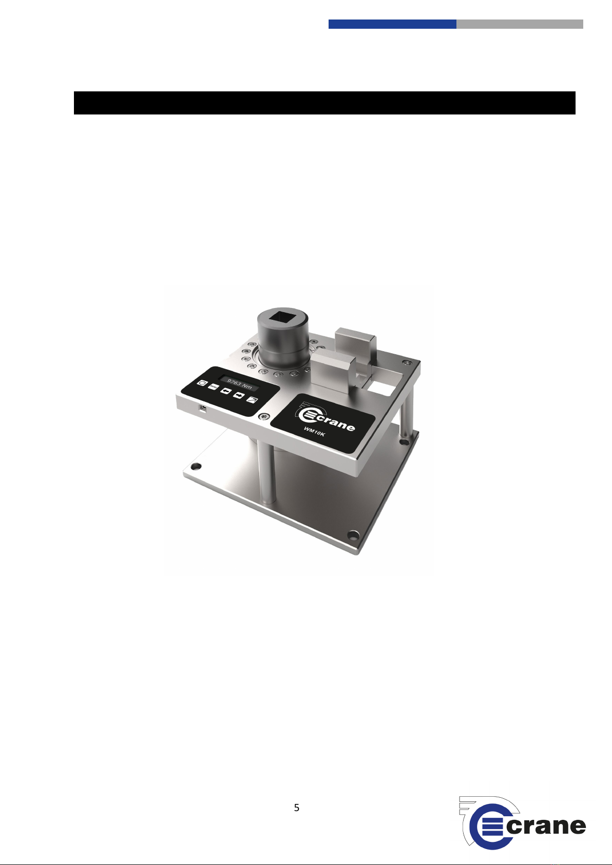
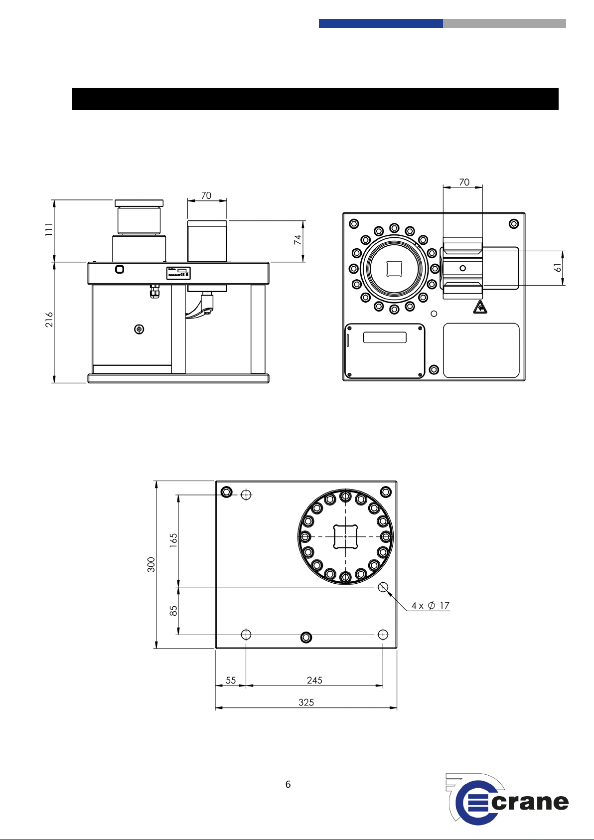
Weight: 50 Lbs [23 kg].
FEATURES AND DIMENSIONS – WM10K

7
Crane Electronics Ltd
The force in torque management
Crane Electronics Ltd
Watling Drive
Sketchley Meadows
Hinckley LE10 3EY
Tel: +44(0) 1455 25 14 88
www.crane
-electronics.com
System Overview:
The WM10K Calibration System allows users to check torque accuracy, run calibration tests, and create
calibration certificates for bolting tools. The WM10K is designed for electric and pneumatic systems.
Not Suitable for use with hydraulic or impact tools
The accuracy of the WM10K is calibrated to meet or exceed: 1% of Full Scale Deflection (FSD) from 2% to 8% of
torque range and 1% of reading from 8% to 100% of torque range.
Main Components:
Run down fixture and transducer – The run down fixture and transducer are designed specifically for the
testing of constant rotation controlled bolting tools. The WM10K features a 1.5” female square drive that can
accommodate other size square drive tools with the use of adaptors. The dynamic fixture provides a fastening
solution that is similar to real life applications. An integrated transducer measures the torque and
communicates the results to the digital display module. The run down fixture can be adjusted vertically to
accommodate various tool designs.
Base plate - The base plate houses the run down fixture, reaction stop, and digital display module. It features
three sturdy legs, end slot to transport the unit, and can be fastened down to a flat surface.
Reaction stop – The reaction stop functions as a counterpoint to the reaction arms of the wrench. The
torque wrench being calibrated is positioned with the reaction arm in between the wings of the reaction stop.
The WM10K features a standard reaction stop that will accommodate most pneumatic and electric tools,
including the PTW-, ETW-Series and many competitive tools. It also features a special reaction post for tools
with configurations that won’t work with the standard reaction stop.
Digital display module –The digital display module facilitates the display, collection, archiving, and processing
of torque readings. The module can run off battery power or plugged into an outlet. Each WM10K is equipped
with a global outlet adaptor that allows the tool to be used with many electrical systems.
SPECIFICATIONS

8
Crane Electronics Ltd
The force in torque management
Crane Electronics Ltd
Watling Drive
Sketchley Meadows
Hinckley LE10 3EY
Tel: +44(0) 1455 25 14 88
www.crane
-electronics.com
Electrical Connections
The digital display module includes a USB/battery charger port as shown below:
DC Interface - The interface for the 5V DC USB AC adapter is supplied with the WM10K. Use the adapter if you
plan on using the main power source.
Use only the AC adapter provided with the WM10K. If another power source is used it will void the warranty
and may cause severe damage to the digital display module.
USB Connections - The USB interface cable shown below is used when downloading to a computer, or other
device. The values are sent every time a reading in Peak mode is taken on the WM10K.
Charging the Battery - Follow the standard operating procedures in your workplace and be sure to observe all
communicated safety precautions.
-The battery for the WM10K should last approximately 12 hours when fully charged.
-The battery is charged any time the WM10K is plugged-in. The charge time is between 2 and 4 hours
depending on the battery charge level. It is recommended that the user unplug the unit when it is not in
use. This will not harm the unit and will increase battery life.
NOTE: If the WM10K is stored for several months, ensure the battery is completely charged prior to storage.
9
Crane Electronics Ltd
The force in torque management
Crane Electronics Ltd
Watling Drive
Sketchley Meadows
Hinckley LE10 3EY
Tel: +44(0) 1455 25 14 88
www.crane
-electronics.com
Power Requirements: The unit will have an internal rechargeable Li-Ion battery pack.
External power for charging will be supplied via a 5V DC USB power supply.
The unit will meet IP51. (Limited protection against dust ingress. Protected
against vertically falling drops of water or condensation.)
USB Data output is a requirement via USB type B connector.
Operating Temperature:32°F [0°C] to 122°F [50°C].
Accuracy: The accuracy of the WM10K is calibrated to meet or exceed: 1% of FSD
from 2% to 8% of torque range and 1% of reading from 8% to 100% of
torque range.
Range: 2% to 100% [148 Ft.lbs to 7375 Ft.lbs (200Nm to 10,000NM)].
Filter: Selectable Hz filter: 125, 250, 500, 1000, 1500, and 2000.
Torque Measurement: Display up to 5 significant figures. Sample every 20 micro seconds
Warranty: 12 months parts and labour against faulty workmanship or materials.
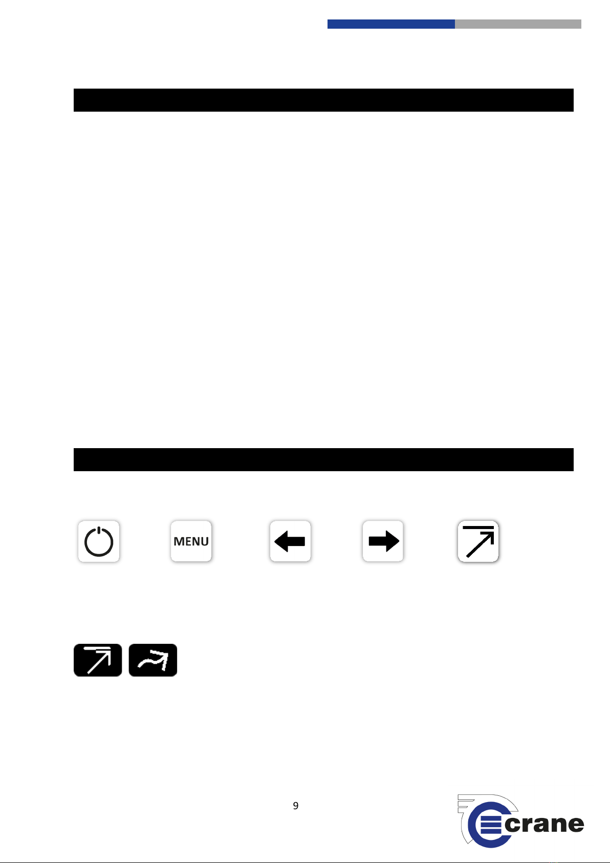
Fixed soft-key Icons:
On-screen Icons - Measurement Modes:
Measurement
Modes
ICONS – WM10K
Peak
Track
TECHNICAL FEATURES
Power
Menu
Left Key
Right Key

10
Crane Electronics Ltd
The force in torque management
Crane Electronics Ltd
Watling Drive
Sketchley Meadows
Hinckley LE10 3EY
Tel: +44(0) 1455 25 14 88
www.crane
-electronics.com
Mount the tool:
Remove the WM10K components from the packaging and place on a flat surface. Ensure that the digital
display module is plugged in or sufficiently charged to operate.
Select and position an appropriate adaptor onto the run down fixture to allow the proper mounting of the
tool.
Mount the tool vertically onto the run down fixture, positioning the reaction arm between the reaction stop
wings, and lower the tool into position. For safe operation, the square drive of the tool must fit into the run
down fixture, with the reaction arm positioned to fully engage the reaction stop as shown in the image below:
START UP

11
Crane Electronics Ltd
The force in torque management
Crane Electronics Ltd
Watling Drive
Sketchley Meadows
Hinckley LE10 3EY
Tel: +44(0) 1455 25 14 88
www.crane
-electronics.com
Adjust the rundown fixture and reaction stop:
If the tool will not fit as indicated, the run down fixture can be adjusted vertically, and the reaction stop can be
adjusted in a straight line perpendicular to the run down fixture (see image below).
Run Down Fixture - To vertically adjust the run down fixture, use the appropriate adapter that provides the
required positioning to achieve full reaction arm engagement. It is important to reverse (loosen) the run down
fixture for testing.
Reaction Stop - To adjust the reaction stop, loosen the handle as shown in the image below. Slide the reaction
stop to properly position the reaction arm and fully engage the reaction stop per manufacturer’s
recommendation. Slide the reaction stop to the desired position. Lock into place by rotating the lock handle
located directly under the reaction stop.
Once the WM10K unit has been appropriately adjusted, complete the mounting of the tool.
Handle

12
Crane Electronics Ltd
The force in torque management
Crane Electronics Ltd
Watling Drive
Sketchley Meadows
Hinckley LE10 3EY
Tel: +44(0) 1455 25 14 88
www.crane
-electronics.com
Check torque with digital display:
Activate the tool, ensure that all safety precautions are being followed. Take note of potential pinch points
when handling the tool during calibration testing.
After the tool stalls, the peak reading will momentarily appear on the display module, and then is saved. For
the next cycle it is important to reverse the tool and loosen the run down fixture.
NOTE: The default setting for the torque reading is peak. To take a peak reading, ensure that the “Peak” icon
appears under the torque reading on the display module (see image below).
Power – Turns the display unit Off and On and also zeros the transducer.
Menu – Accesses torque units and filter settings.
Left & Right Keys – Navigate through the menu and allows access to stored
readings.
FIXED ICONS
OPERATION

13
Crane Electronics Ltd
The force in torque management
Crane Electronics Ltd
Watling Drive
Sketchley Meadows
Hinckley LE10 3EY
Tel: +44(0) 1455 25 14 88
www.crane
-electronics.com
Peak / Track Measurement Mode – Switch between Peak and Track measurement
modes.
Peak Mode
The peak mode displays and retains the maximum torque experienced by the wrench, as occurs when operating
the wrench in the tightening direction. The peak mode is recommended for rotary tools and wrenches.
Track Mode
The track mode displays the torque as it is being applied to the transducer. This mode is used primarily for
verifying the calibration of the WM10K unit.
Press the Menu button and then press
the left and right arrow keys to scroll
through the measurement units,
selecting either Nm or Ft.lbs.
Use this option to select the filter value.
Press the Menu button twice and using
the arrow keys, select the required
Filter. Selectable filter values in Hz (125,
250, 500, 1000, 2000, 4000 and 5000).
The filter is used to reduce mechanical
noise when used with impulse type
tools. Current ISO standards
recommend 500Hz for general use.
MEASUREMENT UNITS
FILTERS
14
Crane Electronics Ltd
The force in torque management
Crane Electronics Ltd
Watling Drive
Sketchley Meadows
Hinckley LE10 3EY
Tel: +44(0) 1455 25 14 88
www.crane
-electronics.com
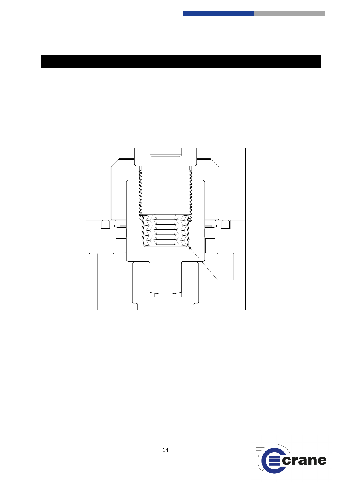
The WM10K Calibration System requires very little maintenance, but periodic lubrication of the run
down fixture is critical to the longevity of the tool. The run down bolt and disc spring should be
periodically removed and inspected, and if necessary, coated with a high pressure anti-seize
lubricant.
Crane recommends Molybdenum Disulfide, or a lubricant with similar properties. After proper
lubrication, replace the run down disc spring. Some units have additional disc springs installed.
MAINTENANCE
Disc Spring
Replacement

15
Crane Electronics Ltd
The force in torque management
Crane Electronics Ltd
Watling Drive
Sketchley Meadows
Hinckley LE10 3EY
Tel: +44(0) 1455 25 14 88
www.crane
-electronics.com
Digital Display
Symptom
Remedy
Digital module will
not turn on.
Plug unit into charger/power supply.
Let unit charge for 30 minutes before attempting to turn on.
Digital display should be connected to power source for 4 hours to fully charge the
battery.
No readings on
digital display.
Check direction of tool is set to RH (Clockwise).
Ensure the target torque setting on the tool is above 100Nm (73.8Ft. lbs)
Torque readings are
dramatically lower
or higher than
expected.
Verify that the display is operating in the desired engineering units.
Check that the filter setting is suitable for the application and the tool.
Inspect transducer for overload/yield by selecting track mode on the display. If there
is a large value displayed with no strain on the transducer the transducer has been over
loaded and requires service.
Joint Run Down
Symptom
Remedy
Threaded
components do not
rotate freely.
Disassemble, clean, and inspect threaded components. If threads are not damaged
lubricate and reassemble.
Service, Repair and Calibration
All service, repair or calibration requirements for the WM10K can be handled by Crane Authorized
Service Centers. For more information, contact Crane Electronics on +44(0)1455251488, email
service@crane-electronics.com or visit www.crane-electronics.com for more information.
TROUBLESHOOTING
Table of contents
Other Crane Electronics Test Equipment manuals


