Crane Saunders P345 User manual

SAUNDERS®- P345
PNEUMATIC ACTUATOR
Normally Closed
www.cranecpe.com
INSTRUCTION MANUAL
REDUCING CO2EMISSION IMPACT ON ENVIRONMENT BY 11%
NEW!

www.cranecpe.com
2
Contents
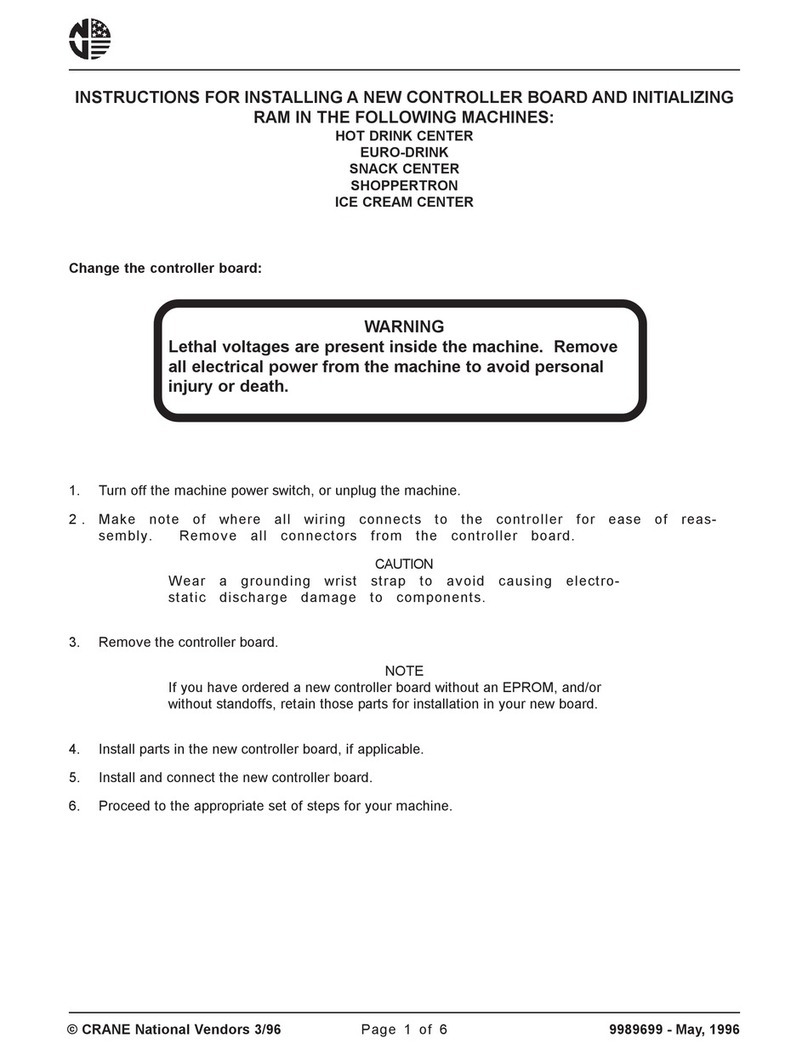
Safety Instructions ………………………………………………………………………………………3
Actuator change out – Disassembly procedure………………………………………………………...4
Diaphragm Removal ……………………………………………………………………………………4
Diaphragm Replacement ……………………………………………………………………………....4
Assembly Procedure …………………………………………………………………………………...5
Torque Specication Table ……………………………………………………………………………..6
Compressor Change …………………………………………………………………………....………6
Product Markings …………………………………………………………………………………....…7
P345 Product Weights …………………………………………………………………………………7

3
www.cranecpe.com
Safety Instructions
Basic Safety instructions
These safety instructions do not make allowance for the
following :
• Contingencies and events which may arise during the
installation, operation and maintenance of the Actuator.
• Local safety regulations - the operator is responsible for
observing these regulations, also with reference to the
installation personnel.
High Pressure:
Before removing the Valve/Actuator fastenings, note the
following:
• For normally closed (NC) Valves, apply air to activate
the Actuator to the open position.
Ensure that the line pressure has been removed and the
system is drained and ushed.
Please ensure that you have the correct tools and safety
equipment to disassemble valves correctly following the
recommended safe working practices.
Hazardous Situation
To avoid injury, ensure the following:
• The system cannot be activated unintentionally.
• Installation and maintenance may be carried out by
authorized technicians only.
• After an interruption in the power or pneumatic supply,
ensure that the process will be restarted in a dened and
controlled manner.
ATTENTION
!

www.cranecpe.com
4
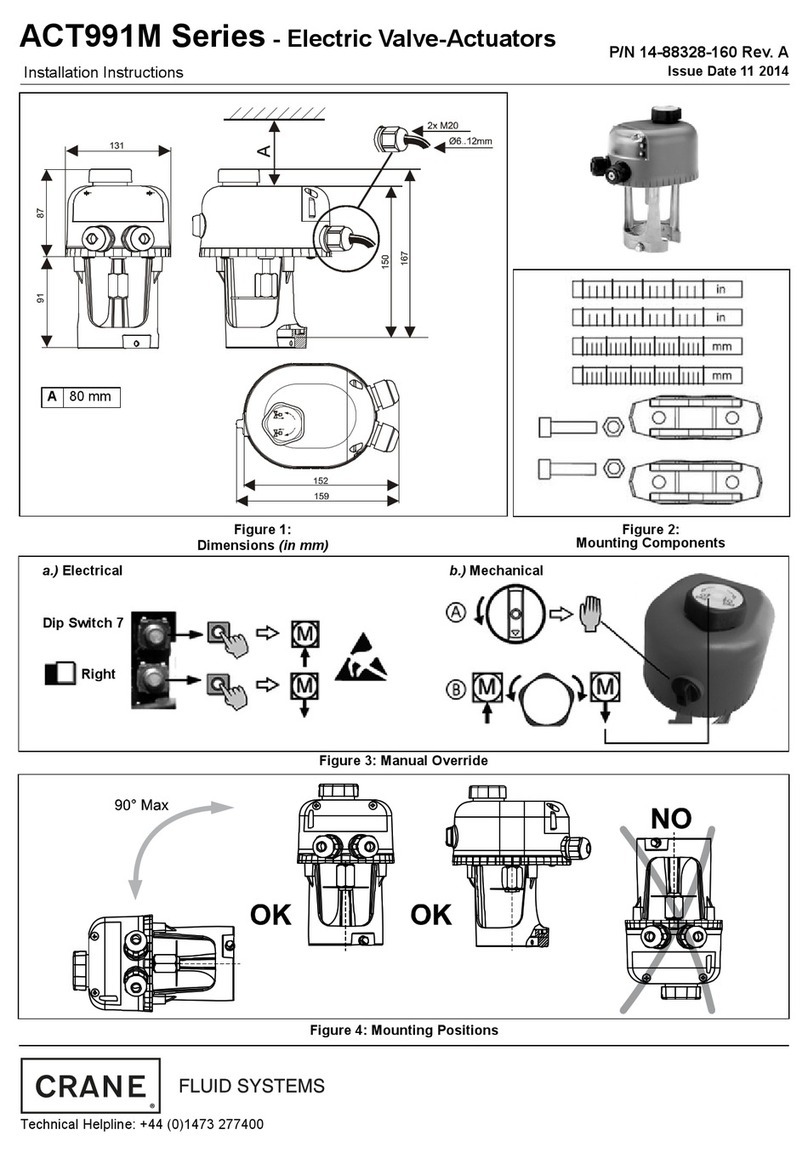
Saunders P345 Pneumatic Actuator
Installation, Operation & Maintenance
1. Actuator Change Out Disassembly
Procedure
Start to loosen the fastenings
Important: Ensure the excess pressure has vented prior to
fastening removal
2. Removal of fastenings & actuator
Remove the fasteners and the valve actuator
3. Diaphragm Removal
Inspect the valve body Sealing surfaces for damage.
4. Removal of fastenings & actuator
Ensure actuator is in the closed position:
Release air pressure on NC Actuators
Compressor face must be exposed.
This will provide better access to the diaphragm,
compressor and xing
5. Diaphragm Replacement
Remove Diaphragm From Actuator
• If one piece elastomer (threaded attachment), rotate
anticlockwise.
• If PTFE with elastomer backing(bayonet attachment), turn
through 90°

5
www.cranecpe.com
Saunders P345 Pneumatic Actuator
Installation, Operation & Maintenance
6. Elastomer Single piece Diaphragm
Engage diaphragm threaded stud into the compressor by
applying pressure to the centre of the diaphragm. Ensure
correct engagement and continue to rotate clockwise
until resistance felt. Rotate diaphragm anti-clockwise until
diaphragm bonnet hole alignment is achieved
7. PTFE Faced Two Piece Diaphragm
Engage diaphragm bayonet into the compressor slot by
applying pressure to the centre of the diaphragm. Ensure
correct engagement and continue to apply pressure to the
centre of the diaphragm and turn through 90°
8. Ensure actuator is full open
Apply air pressure to ‘NC’ actuators.
Attach the actuator to valve body;
Insert the retaining fasteners.
Hand tighten fasteners in the order
shown in Figure 1.
Use diagonally opposing technique to tighten fastenings at
all times.
9. Ensure actuator is in the closed
position:
• Release air pressure on
‘NC’ actuators
10. Gradually tighten the fasteners as per gure 1 to
approximately 3/4 of full torque. (See torque specication
table). This ensures that the diaphragm seats correctly
before further tightening
11. Ensure Actuator is fully open:
• Apply air pressure to ‘NC’actuators

www.cranecpe.com
6
Saunders P345 Pneumatic Actuator
Installation, Operation & Maintenance
12. Tighten all fasteners to the specied torque setting as per
gure 1. (see torque specication table)
• It is recommended that torque is applied to the nut. (For DN8
(1/4”) Actuators, apply torque to the bolt head.)
• It is recommended that the nal torque is applied in three
passes following the correct sequence.
• Re-apply the nal torque to the rst nut after the third pass
to ensure the application of a consistent torque across all
fastenings.
• The compression of the diaphragm periphery should be
consistent.
• The exposed threads at the top of the nuts should be
consistent in length.
13. This determines that even compression has been applied
to all fastenings.
Remove air pressure from Actuator
IMPORTANT: Re-tighten fastenings to the maximum torque
after 24 hours or rst heat cycle.
It is recommended that the retightening operation should be
carried out with the valve in the open position and the valve
temperature 40°C or below.
Tools required for installation
14. Insert at head screwdriver (3mm x 100mm) through the
compressor.
15. Engage screwdriver into spindle adaptor slot.
Torques
Torque Specification Table
Valve Size Maximum Torque
(DN) (Nm)
8 3
15 6.6
20 6.6
25 8
40 17
50 33
65 47
80 67
100 53

7
www.cranecpe.com
Saunders P345 Pneumatic Actuator
Installation, Operation & Maintenance
16. Unwind the spindle adaptor releasing the compressor
17. Assemble replacement compressor/spindle adaptor sub
assembly and apply Loctite 222 to thread.
18. Assemble replacement spindle adaptor/compressor
sub assembly to master spindle on actuator with at head
screwdriver.

www.cranecpe.com
8
Marking
Each actuator is laser etched, containing the following
information:
• Model
• Size
• Mode of Operation
• Operating Pressure
• Date of Manufacture
• QR Code Link to Crane CPE Product Website
Weights Table
Available Accessories
• Position Feedback Switchboxes
• Positioners
• Adjustable Limit Open Stop
• Other accessories available on request
Saunders P345 Pneumatic Actuator
Product makings & Weights
Valve Size
(DN)
Valve Weight
(kg/lbs)
8 0.4 / 0.9
15 0.8 / 1.8
20 1.3 / 2.9
25 1.8 / 4.0
40 3.0 / 6.6
50 6.1/ 13.2

9
www.cranecpe.com
Saunders P345 Pneumatic Actuator
Product makings & Weights Notes

CPE-SAUNDERS-P345-IM-EN-LT-2022_05_05
Crane Co., and its subsidiaries cannot accept responsibility for possible errors in catalogues, brochures, other printed materials, and website information. Crane
Co. reserves the right to alter its products without notice, including products already on order provided that such alteration can be made without changes being
necessary in specications already agreed. All trademarks in this material are the property of the Crane Co. or its subsidiaries. The Crane and Crane brands logotype
(CENTER LINE®, COMPAC-NOZ®, CRANE®, DEPA® & ELRO®, DOPAK®, DUO-CHEK®, FLOWSEAL®, GYROLOK®, GO REGULATOR®, HOKE®, JENKINS®, KROMBACH®, NOZ-CHEK®,
PACIFIC VALVES®, RESISTOFLEX®, REVO®, SAUNDERS®, STOCKHAM®, TEXAS SAMPLING®, TRIANGLE®, UNI-CHEK®, VALVES®, WESTLOCK CONTROLS®, WTA®, and XOMOX®)
are registered trademarks of Crane Co. All rights reserved.
CRANE CHEMPHARMA & ENERGY
Crane Process Flow Technologies Ltd.
Grange Road
Cwmbran, Gwent
NP44 3XX, United Kingdom
Tel.: +44 1633 486666
Table of contents
Other Crane Controllers manuals


