Cranford Controls IS-CP4B-PB User manual

IS-CP4B-PB
Manual Call Point –Push Button
With resistor Modules
For use in Flammable Gas and
Combustible Dust Atmospheres
1) Introduction
The IS-CP4B-PB is a push button manual call point
which is certified intrinsically safe to the European
and International Gas standards. The unit meets
the requirements of the ATEX directive 94/9/EC
and IECEx scheme.
The call point can be used in hazardous areas
where potentially flammable gas atmospheres may
be present.
The IS-CP4B-PB has up to two monitoring
resistors. The units are Group II, EPL (equipment
protection level) Ga. The equipment is certified ‘Ex
ia IIC T4 Ga’ and as such may be used in Zones 0,
1 and 2 with flammable gases and vapours with
gas groups IIA, IIB & IIC and temperature classes
T1, T2, T3 and T4.
The equipment needs to be installed with ATEX
and/or IECEx certified Zener Barriers or Galvanic
Isolators.
2) Marking
All units have a rating label, which carries the
following important information:-
Unit Type No.:
IS-CP4B-PB Manual Call Point
Code:
Ex ia IIC T4 Ga
IP66
Ui=30V Ii=500mA Pi=1.1W Ci=0 Li=0
–40ºC <= Ta <= +50ºC
Certificate No.:
SIRA 09ATEX2287X
IECEx SIR 09.0122X
Epsilon x: II 1G
CE Marking
Notified body No. 0518
Year/Serial No. i.e. 10/1CP4BPB000001
WARNING - DO NOT OPEN WHEN AN
EXPLOSIVE ATMOSPHERE MAY BE PRESENT
3) Type Approval Standards
The beacon has an EC Type examination
certificate issued by SIRA and have been approved
to the following standards:-
EN 60079-1:2006 / IEC 60079-0:2004
EN 60079-1:2009 / IEC 60079-0:2007
EN 60079-11:2007 / IEC 60079-11:2007
EN 60079-26:2007 / IEC 60079-26:2006
EN 61241-0:2006 / IEC 61241-0:2004
EN 61241-1:2004 / IEC 61241-1:2004
The equipment is certified for use in ambient
temperatures in the range -40oC to +50oC and shall
not be used outside this range.
4) Installation Requirements
Installation of this equipment shall only be carried
out by suitably trained personnel in accordance
with the applicable code of practice e.g. IEC
60079-14/EN 60079-14 and IEC 61241-14/EN
61241-14.
Repair of this equipment shall only be carried out
by the manufacturer or in accordance with the
applicable code of practice e.g. IEC 60079-19/EN
60079-19.
The certification of this equipment relies on the
following materials used in its construction:
Enclosure: Aluminium Pressure Die Cast Body
LM6
Through enclosure mechanism: Plastic Nylon Zytel
Injection Moulded
Sealing of enclosure and mechanism: O-ring
Acrylonitrile-Butadiene Rubber
If the equipment is likely to come into contact with
aggressive substances, then it is the responsibility
of the user to take suitable precautions that prevent
it from being adversely affected, thus ensuring that
the type of protection is not compromised.
“Aggressive substances” - e.g. acidic liquids or
gases that may attack metals, or solvents that may
affect polymeric materials.
“Suitable precautions” - e.g. regular checks as part
of routine inspections or establishing from the
material’s data sheet that it is resistant to specific
chemicals.
Refer to certificates SIRA 09ATEX2287X and
IECEx SIR 09.0122X for special conditions of safe
use.
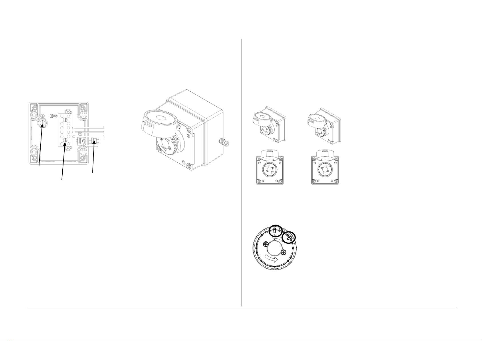
5) Call Point Location and Mounting
The location of the call point should enable ease of
access for operation and testing. The unit should
be mounted using the 4 off fixing holes which will
accept up to M4 sized fixings.
When installing in Zone 0 applications, ensure that
the equipment enclosure is protected from impact.
View of base unit showing fixing centres.
To gain access to the mounting holes in the base
the front cover must be removed.
This is achieved by removing the 4 off M4 cap
head bolts holding on the cover.
Once the screws are removed the cover will hang
down out of the way to gain access to the Ex e
terminal block, the internal earth terminal and
mounting hole recesses.
INSTRUCTION MANUAL
IS-CP4B-PB Push Button Manual Call Point
For use in Flammable Gas and Dust Atmospheres
Zone 1
Explosive gas air mixture likely to occur in
normal operation.
Zone 2
Explosive gas air mixture not likely to occur,
and if it does, it will only exist for a short time.
www.acornfiresecurity.com
www.acornfiresecurity.com
6) Earthing
The unit has both internal and external earth
terminals.
It is recommended that a cable crimp lug is used
on the earth wires.
The internal earth wire is placed under a earth
clamp which will stop the cable twisting. This
secured by an M4 screw and spring washer.
The external earth lug should be located between
the two M5 washers provided and securely locked
down with the M5 spring washer and two locknuts.
Internal Earth
terminals External
Earth Stud
Terminal block
7) Cable connections
There are 3 off cable entries for M20x1.5 cable
glands or stopping plugs.
Cable glands or stopping plugs must be rated IP66.
The unit can be wired in a number of different ways
depending on the resistor combination selected.
Option 1 –EOL (End of line) Resistor
Option 2 –Series (In line) resistor
Option 3 –Series and EOL resistors
The equipment needs to be installed with ATEX
and/or IECEx certified Zener Barriers or Galvanic
Isolators.
8) Testing unit operation
The push button unit can be tested without the
need to replace any element.
To test, lift the cover lift flap to reveal the push
button. The button should be pressed into the body
to activate the unit and place it into the operated
condition.
The call point switch will now change over it’s
contacts to operate the alarm.
Once testing is complete the unit needs to be reset
from the operated condition.
Rotate the push button anticlockwise by an angle
of 55º, see guide alignment marks on button and
cover, shown below (1). The push button should
pop back up to its original position.
Ensure that the push button has also twisted back
clockwise by 55º to its original position see guide
marks on button and cover, shown below (2).
The unit is now reset.
1. On operated unit 2. Button should pop
Twist push button up and twist back to
Anticlockwise 55º original position
to reset
Note: use alignment
marks circled to
indicate the push
button’s status
/position.
Unit currently shown
as ‘standby
condition’
Resetting an operated unit is the same as resetting
a tested unit.
www.acornfiresecurity.com
www.acornfiresecurity.com

1A - Circuit shown in Unoperated condition
Terminals +(2,3) & -(4,5) open
Terminals +(2,3) & (6) closed
EOL (End Of Line ) Resistor
1B - Circuit shown in Operated condition (Button Pressed in)
Terminals +(2,3) & -(4,5) closed
Terminals +(2,3) & (6) open
Series Resistor
2A - Circuit shown in Unoperated condition
Terminals +(2,3) & -(4,5) open
Terminals +(2,3) & (6) closed
2B - Circuit shown in Operated condition (Button Pressed in)
Terminals +(2,3) & -(4,5) closed
Terminals +(2,3) & (6) open
EOL & Series Resistors
3A - Circuit shown in Unoperated condition
Terminals +(2,3) & -(4,5) open
Terminals +(2,3) & (6) closed
3B - Circuit shown in Operated condition (Button Pressed in)
Terminals +(2,3) & -(4,5) closed
Terminals +(2,3) & (6) open
www.acornfiresecurity.com
www.acornfiresecurity.com
Popular Fire Alarm manuals by other brands


E2S
E2S BExTBG05D instruction manual

Teknim
Teknim TWS-1815 Installation & user manual

Ziton
Ziton ZP1-F2 installation manual

Honeywell
Honeywell Fire-Lite Alarms LCD-80F manual

Teknim
Teknim TFB-1166 Installation & user manual

Silent Call Communications
Silent Call Communications FA41-MC Installation and operating instructions