CC
Proceed as follows:
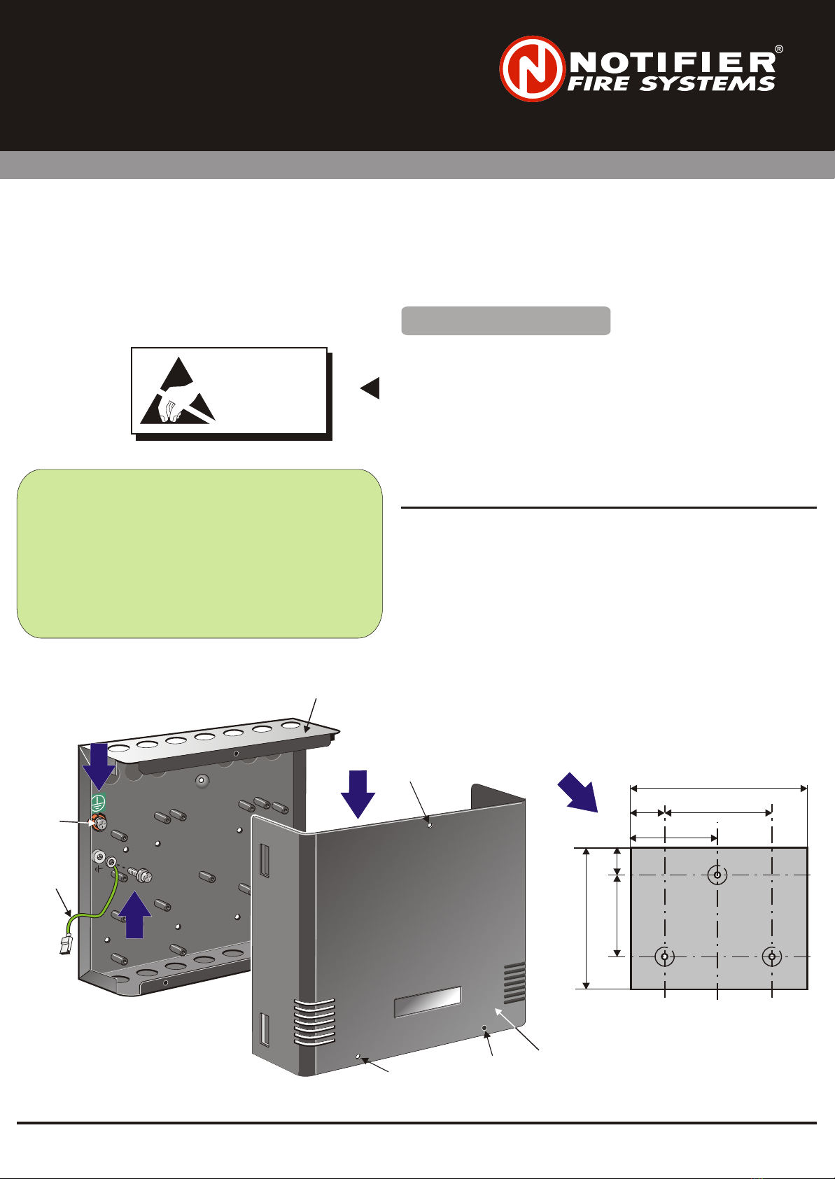
1Using an appropriate-sized screwdriver, remove (and discard) the three
M3 screws (position A) that secure the cover (B) to the back box (C), then
lift off, remove and retain the cover.
2Find a suitable location to install the enclosure, then use the dimensions
below to measure the mounting hole positions. Using a suitable-sized
drilling bit for holes to take 6mm (#12) screws, drill the holes and fit wall
plugs, then secure the back box to the wall with three 6mm (#12) screws.
Open the knock-outs as required and remove any swarf.
3Connect the back box to earth at the safety earth point (D).
4Use one of the M4 SEMS (E) to connect the earth lead (F) to the back box.
Proceed as follows:
Using an appropriate-sized screwdriver, remove (and discard) the three
M3 screws (position A) that secure the cover (B) to the back box (C), then
lift off, remove and retain the cover.
Find a suitable location to install the enclosure, then use the dimensions
below to measure the mounting hole positions. Using a suitable-sized
drilling bit for holes to take 6mm (#12) screws, drill the holes and fit wall
plugs, then secure the back box to the wall with three 6mm (#12) screws.
Open the knock-outs as required and remove any swarf.
Connect the back box to earth at the safety earth point (D).
Use one of the M4 SEMS (E) to connect the earth lead (F) to the back box.
1
2
3
4
Check Your Equipment....Check Your Equipment....
The Multi-Mount Enclosure (PN: 002-439) is very simple to fit to a wall providing the instructions described below are
followed. The Enclosure is capable of housing: one CMX-10RM or MMX-10M or MCX-55 module, or up to two MRM,
MMX, CMX, ZMX or ISO-X modules, or one MULTI-MX module, or one IM-10 or CR-6 or SC-6 or CZ-6 module, or one
Serial NION Board. The Enclosure is secured to a wall using three 6mm (#12) screws.
The Multi-Mount Enclosure (PN: 002-439) is very simple to fit to a wall providing the instructions described below are
followed. The Enclosure is capable of housing: one CMX-10RM or MMX-10M or MCX-55 module, up to two MRM,
MMX, CMX, ZMX or ISO-X modules, one MULTI-MX module, one IM-10 or CR-6 or SC-6 or CZ-6 module, one
Serial NION Board. The Enclosure is secured to a wall using three 6mm (#12) screws.
or
or or or
Taking suitable precautions, before proceeding with the installation, remove
all packaging and inspect for any damage that may have occurred during
transit. If no damage is evident, proceed using the instructions below. In the
unlikely event that damage has occurred, DO NOT PROCEED, contact your
supplier and refer to the panel Installation & Commissioning Manual.
Observing all necessary precautions, proceed with the installation of the
Multi-Mount Enclosure.
Fitting the Multi-Mount EnclosureFitting the Multi-Mount Enclosure
OBSERVE PRECAUTIONS
FOR HANDLING
ELECTROSTATIC
SENSITIVE
DEVICES
OBSERVE PRECAUTIONS
FOR HANDLING
ELECTROSTATIC
SENSITIVE
DEVICES
ATTENTIONATTENTION
CC
Proceed as follows:
1Using an appropriate-sized screwdriver, remove (and discard) the three
M3 screws (position A) that secure the cover (B) to the back box (C), then
lift off, remove and retain the cover.
2Find a suitable location to install the enclosure, then use the dimensions
below to measure the mounting hole positions. Using a suitable-sized
drilling bit for holes to take 6mm (#12) screws, drill the holes and fit wall
plugs, then secure the back box to the wall with three 6mm (#12) screws.
Open the knock-outs as required and remove any swarf.
3Connect the back box to earth at the safety earth point (D).
4Use one of the M4 SEMS (E) to connect the earth lead (F) to the back box.
Proceed as follows:
Using an appropriate-sized screwdriver, remove (and discard) the three
M3 screws (position A) that secure the cover (B) to the back box (C), then
lift off, remove and retain the cover.
Find a suitable location to install the enclosure, then use the dimensions
below to measure the mounting hole positions. Using a suitable-sized
drilling bit for holes to take 6mm (#12) screws, drill the holes and fit wall
plugs, then secure the back box to the wall with three 6mm (#12) screws.
Open the knock-outs as required and remove any swarf.
Connect the back box to earth at the safety earth point (D).
Use one of the M4 SEMS (E) to connect the earth lead (F) to the back box.
1
2
3
4
Check Your Equipment....Check Your Equipment....
The Multi-Mount Enclosure (PN: 002-439) is very simple to fit to a wall providing the instructions described below are
followed. The Enclosure is capable of housing: one CMX-10RM or MMX-10M or MCX-55 module, or up to two MRM,
MMX, CMX, ZMX or ISO-X modules, or one MULTI-MX module, or one IM-10 or CR-6 or SC-6 or CZ-6 module, or one
Serial NION Board. The Enclosure is secured to a wall using three 6mm (#12) screws.
The Multi-Mount Enclosure (PN: 002-439) is very simple to fit to a wall providing the instructions described below are
followed. The Enclosure is capable of housing: one CMX-10RM or MMX-10M or MCX-55 module, up to two MRM,
MMX, CMX, ZMX or ISO-X modules, one MULTI-MX module, one IM-10 or CR-6 or SC-6 or CZ-6 module, one
Serial NION Board. The Enclosure is secured to a wall using three 6mm (#12) screws.
or
or or or
Taking suitable precautions, before proceeding with the installation, remove
all packaging and inspect for any damage that may have occurred during
transit. If no damage is evident, proceed using the instructions below. In the
unlikely event that damage has occurred, DO NOT PROCEED, contact your
supplier and refer to the panel Installation & Commissioning Manual.
Observing all necessary precautions, proceed with the installation of the
Multi-Mount Enclosure.
Taking suitable precautions, before proceeding with the installation, remove
all packaging and inspect for any damage that may have occurred during
transit. If no damage is evident, proceed using the instructions below. In the
unlikely event that damage has occurred, DO NOT PROCEED, contact your
supplier and refer to the panel Installation & Commissioning Manual.
Observing all necessary precautions, proceed with the installation of the
Multi-Mount Enclosure.
Fitting the Multi-Mount EnclosureFitting the Multi-Mount Enclosure
OBSERVE PRECAUTIONS
FOR HANDLING
ELECTROSTATIC
SENSITIVE
DEVICES
OBSERVE PRECAUTIONS
FOR HANDLING
ELECTROSTATIC
SENSITIVE
DEVICES
ATTENTIONATTENTION
Your kit should contain:
Multi-Mount Enclosure PN: 002-439
Allen key 2mm PN: 334-051
M3 x 10 SEM screws (5 off) PN: 775-058
M4 x 8 SEM screws (9 off) PN: 776-042
M3 x 20mm nylon spacers (5 off) PN: 423-252
M4 x 45mm nylon spacers (8 off) PN: 423-311
M3 x 6 button-hd. hex. black steel screws (8 off) PN: 775-059
M3 nylon washers (8 off) PN: 790-019
Cable assembly (earth) 225mm M4 blade/ring PN: 082-160 -005
140.3140.3
170.6170.6
280.6280.6
5555
4545
130130
225225
997-286, Issue 3 January 2003
Installing the Multi-Mount EnclosureInstalling the Multi-Mount Enclosure
1
AA
BB
AA
AA
DD
1122
33
FF
EE
44


