CRE TECHNOLOGY - 130, allée Charles-Victor Naudin - Zone des Templiers - SOPHIA ANTIPOLIS - 06410 BIOT - FRANCE
Phone : + 33 (0)4 .92.38.86.82 - www.cretechnology.com - info@cretechnology.com
QUICKSTART GENSYS COMPACT MAINS_EN_B2020
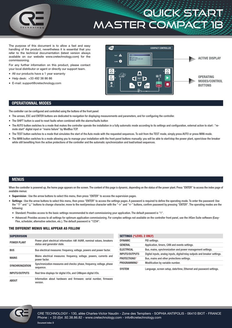
ACTIVE DISPLAY
FUNCTIONNING
MODES/MANUAL
MODE
quick start
gensys COMPACT mains
The purpose of this document is to allow a fast and
easy handling of the product, nevertheless it is es-
sential that you refer to the technical documentation
(latest version always available on our website www.
cretechnology.com) for the commissioning.
For any further information on this product, please
contact your local distributor or agent or directly our
support team.
• All our products have a 1 year warranty
• Help desk: +33 492 38 86 86
• E-mail: support@cretechnology.com
• SKYPE: support-cretechnology.com
OPERATIONNAL MODES
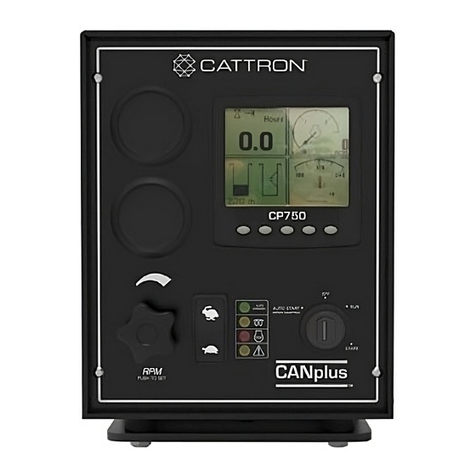
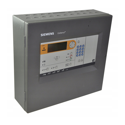
The GENSYS COMPACT MAINS can be configured and controlled with the front panel, which is separated into two parts:
1. The top end and middle part: dedicated to the navigation, monitoring and measure display.
2. The bottom end part: dedicated to the 3 functioning modes selection:
·AUTO - This mode makes the GENSYS COMPACT MAINS operate the installation in a fully automatic mode according to its settings and configuration, external action
to start : “remote start digital input”, Mains failure” or TCP ModBus.
·TEST - This mode simulates the start of the Auto mode with the requested sequences, to exit from the TEST mode, simply press AUTO or press MANUAL mode.
·MANU - This mode allows you to manage your installation with the front panel buttons manually: you will be able to start/stop the generator, open/close the breakers while
still benefiting from the active protections of the GENSYS COMPACT MAINS and the automatic synchronization and power management sequences.
Once the GENSYS COMPACT MAINS is switched on, you can access the menu on 3 different levels (
to access the password page, press ESC. or ENTER):
·Level 0 : No password required, just press «ENTER» to access the display,
·Level 1 : Just press «ENTER» to go on Display menu. Press «↓» to select «configuration» or «system» of the GENSYS COMPACT MAINS. Press «ENTER» to switch to
password mode. Press «↑» to change the character; press «→» to move to the next character. Level 1 password is «1».
NOTE : The Level 1 password gives you access to the minimum settings recommended to start your commissioning on your power plant. This level "1" is equivalent to «stand-
ard mode» on the i4Gen Suite software.
·Level 2 : Just press «ENTER» to go on Display menu. Press «↓» to select «configuration» or «system» of the GENSYS COMPACT MAINS. Press «ENTER» to switch to
password mode. Press «↑» to change the character; press «→» to move to the next character. Level 2 password is «1234».
NOTE : The level 2 password gives you access to all settings to commission your power plant. This level “2” is equivalent to “advanced mode” on the i4Gen Suite software. For
complex settings, which are not available through the front panel of the module, you can use i4Gen Suite (Analogue inputs, Easyflex, Scheduler, etc ..).
MENUS
THE DIFFERENT MENUS WILL APPEAR AS FOLLOW
DISPLAY
GENERATOR
Electrical measures on generator : gen-
eral, voltage, powers, currents, powers
per phase and power factor.
MAINS Electrical measures on Mains : general,
voltage, powers and currents.
SYNCHRO.
Electrical measures on synchronization:
phase, frequency, voltage, phase se-
quence.
ENGINE
Mechanical measures on engine :oil pres-
sure, water temp, speed, battery voltage,
running hours, starts attemps, etc …
INPUTS/
OUTPUTS
Real time displays for digital I/Os, and
CANopen digital I/Os.
MAINTENANCE Real time displays for maintenance
counters on hours, and days.
ABOUT Information on hardware product: serial
number, firmware version.
CONFIGURATION (*LEVEL 2 ONLY)
APPLICATION Installation description: type of operations & Mains paralleling mode.
Level 2: voltage system, power up mode.
TIMERS Timer settings for ramps,breakers,start sequence, stop sequence,Mains & gas engine sequences.
GENERATOR Definition of the electrical measure ratios (PT, CT) and generator nominal values (kW, kVAR,V).
Level 2: high/Low limit, electrical fault.
MAINS Definition of the Mains electrical measure : ratios (PT, CT), nominal values (V, Hz) and Mains kW
measure. Level 2: Mains electrical fault and authorization to start.
SYNCH CHECK RELAY*Voltage, frequency, phase windows acceptance, and fail to synch timer.
POWER MNGT*Load shedding : Under frequency and maximum load settings.
ENGINE Engine definition: Engine type, speed sensor and setpoint, protection switch.
Level 2: Start/Stop settings, J1939, static paralleling.
J1939 ECU/ECM Engine J1939 configuration.
INPUTS/OUTPUTS Digital inputs/outputs settings. Relays outputs settings.
BREAKERS Generator & Mains breakers control settings.
GENERATOR
PROTECTIONS*
Protections on frequency, voltage, current, reverse power, kW, kVAR, unbalance, short-circuit
and earth Fault.
MAINS PROTECTIONS*Ffrequency, voltage, current, reverse power, kW, kVAR, vector shift, Df/Dt and unbalance.
OTHER PROTECTIONS*Speed, oil pressure, water temp, analogue inputs, battery, battery boost, outputs & J1939.
SPEED/AVR CONTROL AVR control (amplitude, offset). Speed governor control (amplitude, offset).
CONTROL LOOPS
Synchro. settings (Global gain Freq, phase, Volt). Power Control (Global gain kW, kVAR),
kW setpoint. Mains permanent mode : base load, peak shaving, and power factor setpoints.
Level 2: Same settings with proportional, integral, derivative.
MODIF BY VAR NUMBER*Personalized settings (for experienced users only).
SYSTEM (*LEVEL 2 ONLY)
EVENTS*Events personalized list to configure.
DATE/TIME Regional settings, on date and time.
SCREEN SETUP Screen settings about contrast, back-
light, screen saver.
ETHERNET Ethernet communication settings, IP, etc..


