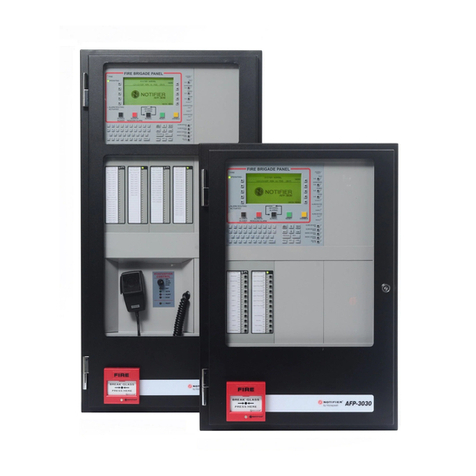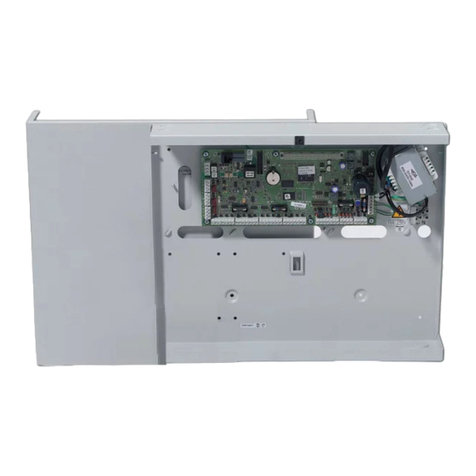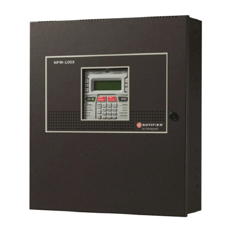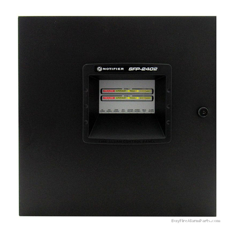
Fire Alarm Control Panel IQ8Control C / M
FB 798951.10.GB0 / 04.15 3
Table of contents
1General / Application.................................................................................................................................................. 5
2Standards and guidelines.......................................................................................................................................... 7
2.1 Approvals.............................................................................................................................................................. 7
3Transport damage inspection.................................................................................................................................... 8
4Configuration variants.............................................................................................................................................. 10
4.1 Special configuration – Swiss option CH ....................................................................................................... 11
4.2 FACP IQ8Control C........................................................................................................................................... 12
4.3 FACP IQ8Control M........................................................................................................................................... 14
4.4 Definition of the Primary loop number.............................................................................................................. 19
5Assembly and installation information .................................................................................................................... 21
5.1 Maintenance / Service....................................................................................................................................... 22
5.2 Assembling the wall housing............................................................................................................................. 23
5.3 Fitting the panel to the mounting surface ......................................................................................................... 24
5.4 Cable glands ...................................................................................................................................................... 27
5.5 Connection between the housings ................................................................................................................... 28
5.6 Operating module / Housing door .................................................................................................................... 29
5.7 Panel buzzer ...................................................................................................................................................... 29
5.8 Housing contact ................................................................................................................................................. 30
6Electronic devices .................................................................................................................................................... 31
6.1 Power supply module (Part No. 802426 index G or higher)........................................................................... 31
6.2 Basic module...................................................................................................................................................... 40
6.3 Software.............................................................................................................................................................. 43
6.4 Field device module........................................................................................................................................... 52
6.5 Extension module .............................................................................................................................................. 64
7Micro module............................................................................................................................................................ 66
7.1 Loop modules..................................................................................................................................................... 66
8Relay module............................................................................................................................................................ 79
8.1 3-relay module / 3-relay common trouble module........................................................................................... 79
8.2 4- Relay module................................................................................................................................................. 84
8.3 Serial interface module...................................................................................................................................... 87
9Master box activation module ................................................................................................................................. 89
9.2 Overview – micro module terminals ................................................................................................................. 93
10 Installer level – Commissioning / Maintenance...................................................................................................... 96
10.1 Primary loop function......................................................................................................................................... 98
10.2 Testing (the loop) ............................................................................................................................................... 99
10.3 Detector replacement ......................................................................................................................................100
10.4 Simulation of detector states...........................................................................................................................102
10.5 Simulation of control states .............................................................................................................................103
10.6 Query of additional and info texts of other control panels (remote text) .....................................................104
10.7 Printer function .................................................................................................................................................105
10.8 Display of the event memory ..........................................................................................................................107
11 Diagnostic display ..................................................................................................................................................108
11.1 Diagnostic display IQ8Control C/M ................................................................................................................108
11.2 The essernet®diagnostic line.......................................................................................................................... 109
11.3 Checking the essernet®devices and connections ........................................................................................111
11.4 Display of the analogue values....................................................................................................................... 112
12 Meaning of the three digit error codes / test mode ..............................................................................................115
12.1 Trouble messages in the display ....................................................................................................................121
