Creator Electronics CR-M4101 User manual

i
CREATOR Electronics
Digital Conference System
Digital Conference System
User Manual
Please read this manual carefully before using this product

ii
CR-PDC08-0A-0
V1.
2008, OTC
NOTICE
The Professional Digital Conference System User Manual provides reference
for the models of CR-M41 1 / CR-ME4 /CR-M41 2 / CR-M41 4 / CR-M41 3E3
/CR-TP41 2/ CR-IR2 -12 / CR-IR1 1-15/ CR-IR2 1-12 / CR-IR2 2-12 /
CR-V1 1 ﹡ / CR-T1 .It is only an instruction for operators, not for any
maintenance usage.
This manual is copyright CREATOR Corporation. All rights reserved. No part of this
publication may be copied or reproduced without the prior written consent of
CREATOR Corporation.
CR-PDC08-0A-0 V1.
Please check CREATOR website or contact local supplier for updates.
http://www.creator.com.cn
iii
!
Safety Operation Guide
In order to ensure the credibility use of the product and the user’s safety, please comply
with the following items during installation and maintenance:
The system must be earthed properly. Please do not use two blades plugs and ensure
the alternating power supply ranged from 1 v to 24 v and from 5 Hz to 6 Hz.
Do not put the machine in a place of too hot or too cold.
To avoid any damage by over heat, please keep the working environment good in
ventilation to radiate the heat when running the machine.
The machine should be turned off when in rainy and humid days or nonuse for a long
time.
The AC power supply line should be disconnected with the power socket during the
following operation.
A. Take out or reinstall any component of the machine.
B. Disconnect or re-connect any connector of the machine.
Please do not attempt to maintain and uncover the machine for there is a high-voltage
component inside and the risk of the electric shock.
Do not splash any chemical product or liquid on or near the equipment.

iv
Index
1.
Digital Conference System Introduction ................................................................. 1
About this system ................................................................................................................... 1
Features of DCS....................................................................................................................... 1
2.
DCS controller............................................................................................................ 2
Product Instruction ................................................................................................................. 2
Front Panel ............................................................................................................................................... 2
Volume ——Adjust the master volume from 1, the minimum, to 6, the maximum. .................................. 2
Rear Panel ................................................................................................................................................ 3
Features .................................................................................................................................................... 3
CR-ME 000 ............................................................................................................................... 5
Front Panel: .............................................................................................................................................. 5
Rear panel: ............................................................................................................................................... 5
Features ................................................................................................................................... 5
Technical Parameter ................................................................................................................ 6
Diagram .................................................................................................................................... 6
3. DCS Speaking Unit .................................................................................................... 7
Product Instruction ................................................................................................................. 7
CR-M 10 A1 ............................................................................................................................ 8
Features .................................................................................................................................................... 8
Features: ................................................................................................................................................ 8
Diagram .................................................................................................................................................... 9
CR-M 102/ A2 ......................................................................................................................... 9
Features: ................................................................................................................................................... 9
Features .................................................................................................................................................. 1
Diagram .................................................................................................................................................. 1
CR-M 102/ B .......................................................................................................................... 11
Features .................................................................................................................................. 11
Features .................................................................................................................................................. 11
Diagram .................................................................................................................................................. 12
CR-M 102/ E ...........................................................................................................................12
Features .................................................................................................................................................. 12
Features .................................................................................................................................................. 13
Diagram .................................................................................................................................................. 13
Embedded Unit .......................................................................................................................1
Features .................................................................................................................................................. 14
Diagram .................................................................................................................................................. 15

v
Features .................................................................................................................................................. 15
CR-M 102/ F ...........................................................................................................................16
Features .................................................................................................................................................. 16
Diagram .................................................................................................................................................. 17
Features .................................................................................................................................................. 17
CR-M 102/ D2 ........................................................................................................................18
Features .................................................................................................................................................. 18
Diagram .................................................................................................................................................. 19
Features .................................................................................................................................................. 19
CR-TP 102D ............................................................................................................................20
Features .................................................................................................................................................. 2
Features .................................................................................................................................................. 23
Diagram ...................................................................................................................................2
Technical Parameter ...............................................................................................................25
4.
DCS Simultaneous Interpretation ........................................................................... 27
CR M4103E3 ................................................................................................................... 27
Features .................................................................................................................................................. 27
Setting menu ........................................................................................................................................... 28
Monitor unit ............................................................................................................................................. 3
Features .................................................................................................................................................. 3
Techinical Parameter ..............................................................................................................31
Diagram ...................................................................................................................................31
5.
DCS IR Language Distribution System .................................................................. 32
Product Description ...............................................................................................................32
CR-IR2000-12 IR Language Distribution System Transmitter Controller ............................32
Destription: .............................................................................................................................................. 32
Features: ................................................................................................................................................. 32
CR-IR2001-12 IR Radiator board ............................................................................................33
Function: ................................................................................................................................................. 33
Features: ................................................................................................................................................. 33
CR-IR2002-8/12 IR Receiver unit ............................................................................................3
Function: ................................................................................................................................................. 34
Features: ................................................................................................................................................. 34
Parameters: .............................................................................................................................35
System Diagram .....................................................................................................................36
6.
DCS Camera auto tracking Controller ................................................................... 37
Instruction ...............................................................................................................................37

vi
MVC- 200 Camera auto-tracking Controller .........................................................................37
Features: ................................................................................................................................................. 37
Technical parameter................................................................................................................................ 38
CR-V1011/V1012 High-speed autodome................................................................................39
Features: ................................................................................................................................................. 39
Technical parameters: ............................................................................................................................. 39
System diagram ...................................................................................................................... 0
7.
DCS Telephone conference module....................................................................... 41
Instruction ............................................................................................................................... 1
Features: ................................................................................................................................. 1
Panel diagram ......................................................................................................................... 1
Technical parameters: ............................................................................................................ 2
System diagram ...................................................................................................................... 2
8.
Accessaries .............................................................................................................. 43
CR-P2 Headphone No Microphone ........................................................................................ 3
Features: ................................................................................................................................................. 43
Technical parameters: ............................................................................................................................. 43
CR-P Headphone with Microphone ..................................................................................... 3
Features: ................................................................................................................................................. 43
Technical parameter:............................................................................................................................... 43
Cable ............................................................................................................................... 44
CR M4KL315 ................................................................................................................... 44
CR CT10 “T”connector .................................................................................................. 44
CR CT20 socket ............................................................................................................. 45
CR CT30 socket ............................................................................................................. 45
CR CT50 8–pin aviation connector ............................................................................... 45
CR HMP24 Expand power ............................................................................................. 45
CR link20 ........................................................................................................................ 45
9.
Annex ........................................................................................................................ 45
Code specification: ........................................................................................................ 45

1
1. Digital Conference System Introduction
About this system
DCS (Digital Conference System), central control system and matrix switcher system are 3 most
important product lines of CREATOR Electronics. It consists of the function modules as contribution,
simultaneous interpretation, IR language distribution, telephone conference, voting and video tracking.
CREATOR is always dedicated to integrated system solutions. Therefore, the DCS is not only a Hi-tech
electronical system, but also a powerful conference control solution while cooperating with the central
control system seamlessly.
New Functionality developed: “Public voting”, this new function allows people to see the name of voter in
real-time mode or save as the document, at the same time, chairman unit’s mic is controllable by PC
software.
Features of DCS
Safety: The safety of every delegate is the most important thing to each conference.
The power of delegate unit and chairman unit are supplied by the central control unit with
24V safety current.
To improve the antistatic performance, the parts are selected carefully to avoid point
discharge current and the earth line is ensured to be enough thick. As a result, the
antistatic performance is up to 8 V.
Security and anti-jamming: Everything discussed in a conference must be important and sensitive.
To keep the signals and information securely and distortion-free is highly required.
The discussion system is shielded-cable linked, which can prevent the radio disturbance
and wiretapping effectively.
Perfect audio quality: The more clearly we “say”, the more clearly we get.
The contribution equipment adopts condenser microphone with unidirectional response.
The contribution equipment adopts built-in hi-fi loudspeaker.
The lightweight earphone with a hanging design can reproduce the audio vividly and it is
comfortable to wear. It is very suitable for a long time use without any feeling of oppressive
or unhappy.
Maneuverability: Simple operation and control represent efficiency.
Easy installation: the communication method of daisy-chaining the units simplify the work
of installation and save the cost.
Easy operation: every one can easily control the unit by press a button to address and turn
the knob to adjust the volume of speaker or earphone.
Maintainability: An excellent system design leads to low maintenance cost, lesser upgrade
expense, long life-span and high efficiency.
The communication method of daisy-chain is easy to maintain and locate the problem unit.
Even the end user technician can maintain the system well with a short-term training.
All the equipments are produced and tested under ISO9 1 strictly. They are international
qualified.

2
Expansibility: The capability of expansible protects users’ benefit and makes the system more
flexible and powerful.
To cope with the increasing number of delegates, the only thing to do is just adding in the
delegate units.
The modular system can be easily expanded by putting in the proper functional module.
When adding in a voting unit, it becomes a voting conference system; when adding in the
camera tracking module, it becomes a simultaneous A/V conference system.
2. DCS controller
Product Instruction
CR-M41 1 controller
CR-ME4 extender
CR-M41 1 controlle
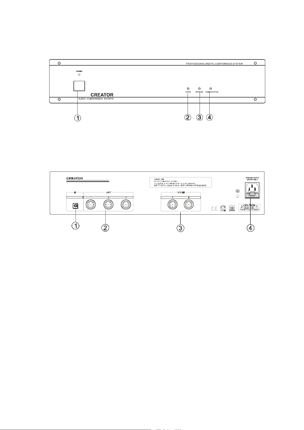
Front Panel
① POWER
② MODE
■ FIFO MODE: It is the first in first out mode with the configurable number of 1/2/4/6 speaking
units, except the chairman unit.
■ NORMAL MODE: The mode with a maximum number of active delegate units. The number of
contribution units may be set to 1/2/4/6, except the chairman unit. When the active
microphones reach the limitation, one delegate unit must be closed to leave the place for the
other who wants to speak.
■ FREE MODE: 2 active units at one time.Without any limitation from Chairman Unit.
■ APPLYMODE,delegate needs permission from Chairman unit before speaking
③ ACTIVE MICRO’S ——configure the maximum number of active microphone to be used at a
same time. Users can choose from 1, 2, 4 and 6
④ BASS ——Adjust bass up to eliminate the howling or squeal and adjust it down to get a more
clear audio reproduction
⑤ TREBLE ——Adjust treble down to eliminate the howling or squeal and adjust it up to get a more
clear audio reproduction
⑥
VOLUME ——Adjust the master volume from 1, the minimum, to 6, the maximum.

3
Rear Panel
789
1
① IN ——It is the audio-in connector to input the audio signal like background music
②OUT 1——It is the audio-out connector to output the audio signal to amplifier or audio recorder.
OUT 2——It is the audio connector to output the audio signal to telephone conference.
③ OUTPUTS ——There are 6 channels of audio-out connectors to output the audio signal to amplifier
or audio recorder etc.
④ INTERPRET ——It is the interface to the interpreter unit. Up to 5 interpreter units can be connected in
the hand in hand daisy-chain
⑤ ROUTE ——It is the expanded interface to the expanded control host. Up to 4 96 contribution units
can access the system by daisy-chaining the expanded hosts hand in hand
⑥ DELEGATES ——It is the interface to the contribution units. There are 3 channels to access the
system, and each can link to not more than 64 contribution units in hand in hand daisy-chain. There
is no limitation for the chairman unit. It can be located anywhere in the chain
⑦ CONTROL SYSTEM ——It is the interface to the CR-PGMⅡcentral control system. Via this interface,
the CR-PGM II can cooperate with the ACS seamlessly and control the conference remotely
⑧ PC ——It is the serial control port to the console PC. With the application on the console pc, users
can control the conference system remotely
⑨ SET ID ——Set “ON” to code the contribution units for the controller and set “OFF” to run normally.
Please refer to the chapter 2.10 Coding Description for the details of coding method.
Setting: After power on, switch the SET ID to “ON”, press the speaking button of delegate
units one by one, the light will be on after setting successful.
⑩ POWER INPUT ——Power supply of 1 V-24 V AC
Features
1 The host itself can provide system accessing for up to 128 contribution units and can be
expanded to 4 96 at the most.
2 It supports 5 interpreter units and achieves 6 languages simultaneously interpretation at a
same time including the original one
3 Communicating in the hand in hand daisy-chain, it is easy to install and maintain
4 Equipped with audio-in connector, it is able to have background music
5 Equipped with enough audio-out connectors, it is able to output the audio signal to different
audio devices
6 Limit function: Restrict present speaking units, when reach the max number, close opened
units then others can start speaking. The number can be 1, 2, 4, and 6.
7 Voice active function can automatically inspect the speaking status, and then control the video
to switch between speaker and main picture.

4
8 FIFO mode can automatically control the active microphones.
9 Working with the telephone coupler, it can open a telephone conference with remote user
1 Cooperating with the central control system, it becomes a powerful conference controller and
achieves the super function of camera auto-tracking.
11 Support voting and data managing。
12 Cover with metal material and earth well to ensure the 8 V antistatic performance
13 Rack-mountable enclosure. It can be installed in the standard 19” rack conveniently.
NOTICE
1.8-pin aviation connector
8 P in M ALE
485A/1
485B/8
GND/2
A+ /3
A+ /5
B+ /6
B- /7
24V+/4
2. CONTROL SYSTEM COM
3. PC COM
PC
SIGNAL INSTRUCTIO
N
1 — —
2 TXD TXD
3 RXD RXD
4 — —
5 GND GND
6 — —
7 — —
8
—
—
Control
System
COM SIGNAL INSTRUCTIO
N
1 — —
2 — —
3 TXD TXD
4 — —
5 GND GND
6 — —
7 — —
8
—
—
5
CR-ME 000
Front Panel:
① POWER and power indicator
② ACTIVE indicator
③ NETWORK indicator
④ COMMUNICATION indicator
Rear panel:
① ID ——ID Setting
② DELEGATES——It is the interface to the contribution units. There are 3 channels to access the
system, and each can link to not more than 64 contribution units in hand in hand daisy-chain.
There is no limitation for the chairman unit. It can be located anywhere in the chain.
③ ROUTE——A is the interface to the controller. B is the expanded interface to another
expanded controller. When in a multilevel expansion, A is the interface to the front level, and B
is the interface to the next level
④ POWER INPUT——Power supply of 1 V-24 V AC
Features
1.8-pin aviation connector
2. Working with CR-M32 1 control host to expand the contribution units in system
3.Input voltage between 1 -24 V, it can endure 35 V high voltage
4. Cover with metal material and earth well to ensure the 8 V antistatic performance
5. Rack-mountable enclosure. It can be installed in the standard 19” rack conveniently
6
Technical Parameter
Technical Parameter CR-M41 1 CR-ME4
Power supply 1 -24 V 1 -24 V
Static consumption 1 W 1 W
Nominal power
consumption 35 W 35 W
Output power ≤11 W/24V ≤11 W/24V
Audio output
Impedance:1 Ω
mode:unbalanced
Impedance:1 Ω
mode:unbalanced
MIC input
Impedance:1 kΩ
Electriclevel:-6 dB
mode:unbalanced
Impedance:1 kΩ
Electriclevel:-6 dB
mode:unbalanced
Frequency response 6 -8kHz 6 -8kHz
(S/N) > 8 dB > 8 dB
Harmonic distortion < .5% < .5%
Harmonic distortion at overload <1% <1%
Crosstalk attenuation at 1kHz >5 dB >5 dB
Weight 6.5KG 6KG
Dimension 483L *275W *88H (mm) 483L * 275W *88H (mm)
Colour Grey Grey
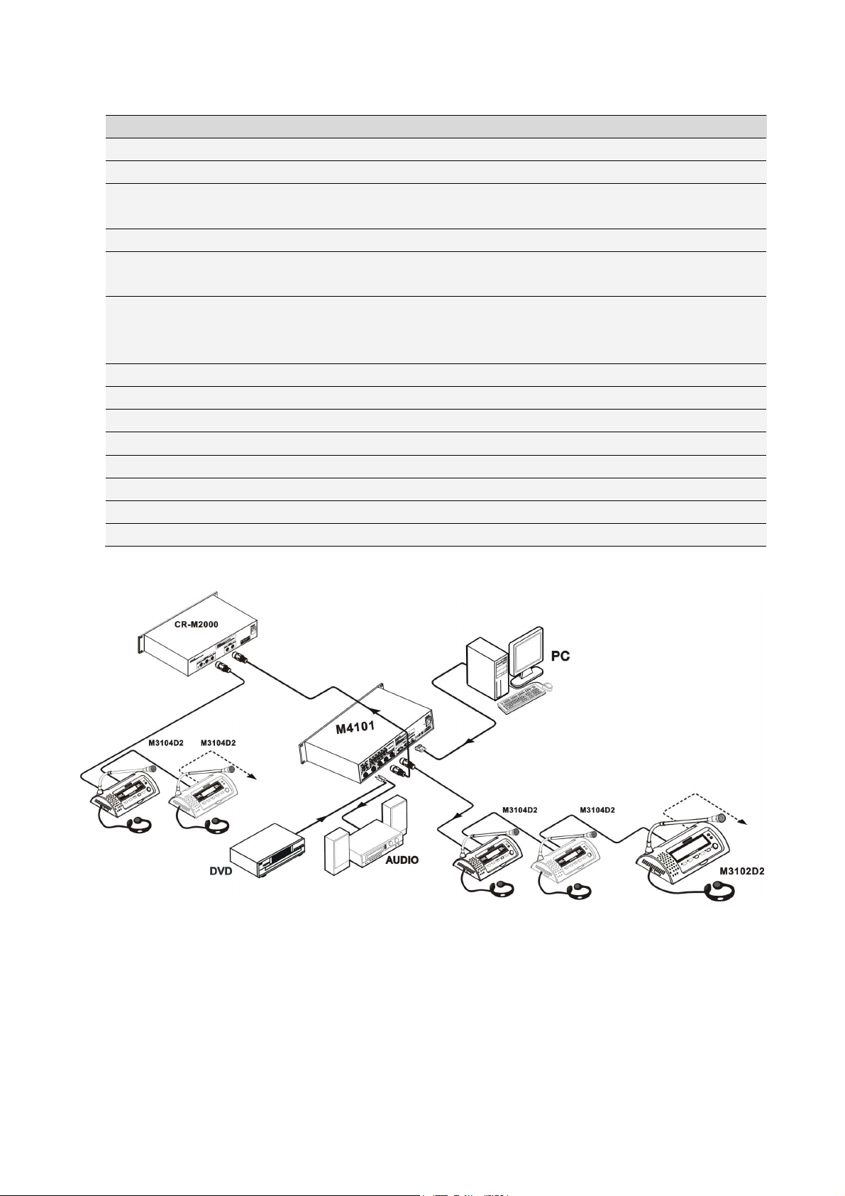
Diagram
Setting ID for conference units:
1. The ID setting for conference units means that, every conference unit in the system (including
interpretation & speech unit) was given the only address for being discerned by the host.
2. setting the conference units as following: after connection finished, turn on the host power, and set
the ‘SET ID’ to ‘ON’, and press speech of the speech & interpretation unit one by one, the light of MIC will
be on, until all the lights are on, we could set the ‘SET ID’ to ‘OFF’, when all the lights of MIC are off, the
system will work under the normal mode

7
3. DCS Speaking Unit
Product Instruction
Model Name Externality MIC Key Voting Channels
Switch
LCD
CR-M41 4A1 Delegate Unit
Fold-away √ × × ×
CR-M41 2A2 Chairman Unit
Fold-away √ √ × √
CR-M41 4A2 Delegate Unit
Fold-away √ √ × ×
CR-M41 2B Chairman Unit
Table-Top √ × × ×
CR-M41 4B Delegate Unit
Table-Top √ × × ×
CR-M41 2C1 ChairmanUnit
Embedded √ × × ×
CR-M41 4C1 Delegate Unit
Embedded √ × × ×
CR-M41 2C4 Chairman
Voting Unit
Embedded × √ × ×
CR-M41 4C4 Delegate
Voting Unit
Embedded × √ × ×
CR-MC4 32B
Chairman
twinaudio box
× × × ×
CR-MC4 34B
Delegate
twinaudio box
× × × ×
CR-M41 2D2 Chairman Unit
Slide √ √ × √
CR-M41 4D2 Delegate Unit
Slide √ √ × √
CR-TP41 2D Chairman Unit
Slide √ √ × √
CR-M41 2E Chairman Unit
Table-Top √ × × ×
CR-M41 4E Delegate Unit
Table-Top √ × × ×
CR-M41 2F Chairman Unit
Embedded √ √ × √
CR-M41 4F Delegate Unit
Embedded √ √ × √

8
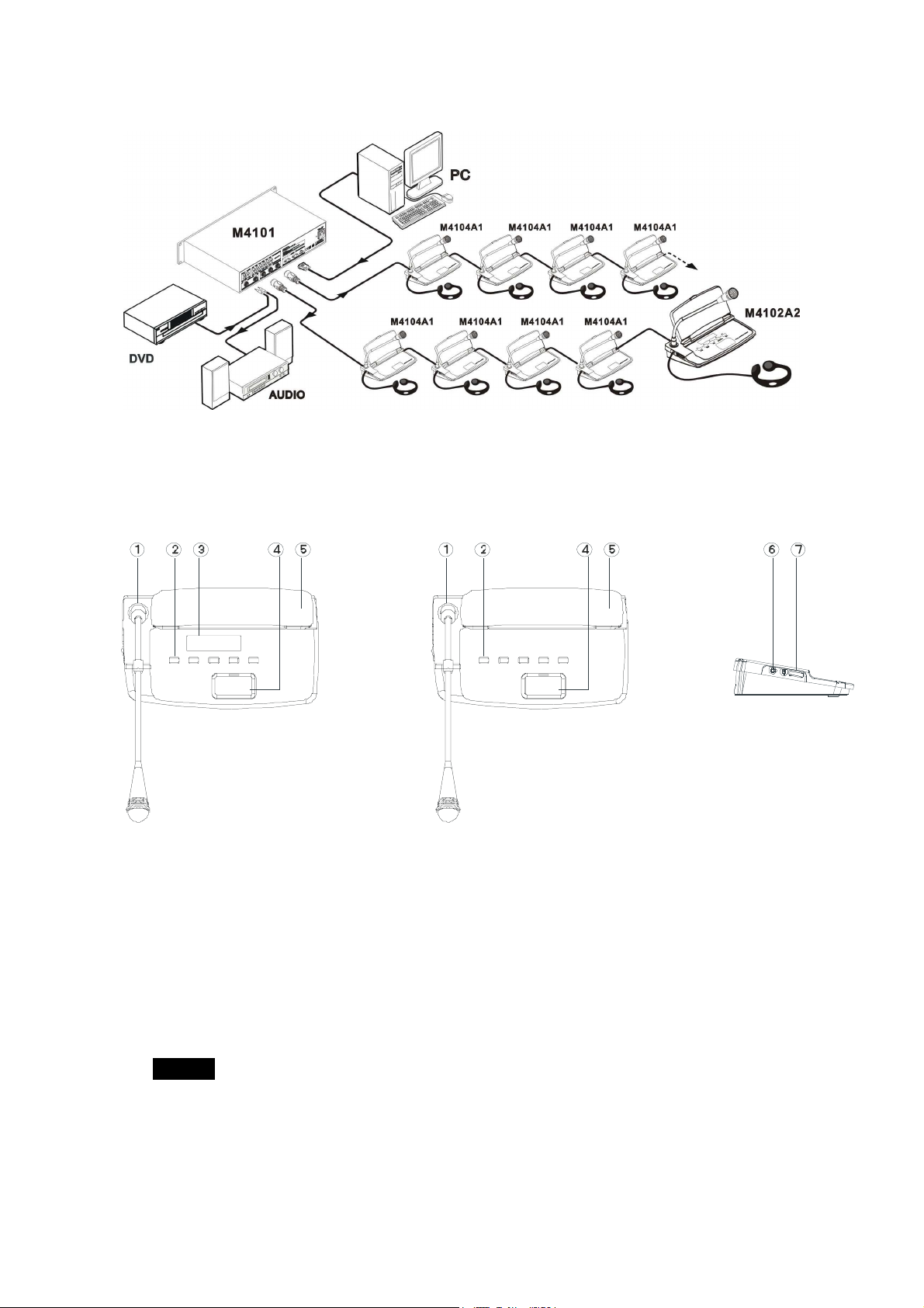
CR-M 10 A1
Features
① Microphone: Pluggable, easy to transport and maintain
② MIC button: Press it to open the microphone and repress it to close the microphone.
③ Build-in flat panel loudspeaker: It will automatically mute while the microphone opens.
④ Earphone jack: Install and connect the earphone for DCS here.
⑤ Volume adjustment: Adjust the volume of the contribution unit
Features:
::
:
1. Voting function integrated
2. 8-pin aviation connector
3. Pluggable unidirectional microphone with red ring indicator
4. Knob pin MIC pole
5. 2M cable for each unit
6. Build-in flat panel loudspeaker and earphone jack with excellent audio quality and adjustable
volume control.
7. The power of delegate unit and chairman unit are supplied by the central control unit with 24V
safety current.
8. Radio disturbance prevention
9. Communicating in the hand in hand daisy-chain or “T”, it is easy to install and maintain.
9
Diagram
CR-M 102/ A2
Features:
CR-M41 2A2 Front View CR-M41 4A2 Front View Side View
① Microphone: Pluggable, easy to transport and maintain
Multi② voting buttons
——For/against: buttons 2/3/4 stand for For/Abstain/Against, respectively.
——Multiple election: buttons 1/2/3/4/5 can stand for different candidates, respectively.
——Evaluation Poll: buttons 1/2/3/4/5 stand for 5 level /-/ /+/++, from low to high.
NOTICE
Button 4 on the chairman unit has a special function of intermission.
The chairman can press to temporarily close all the microphones on delegate units and
release it to resume the conference.
The conference holder can press the START button on the chairman unit to start voting. At this
time, all the contribution units will sound “Di” and the button 1 will flash to ask for confirmation.

10
Then, the delegates should press the button 1 to confirm and start voting.
Their last choice on the buttons will be considered as their final decision and will be indicated by
the button indicator. When the conference holder press the STOP button on the chairman unit,
the voting is finished and all the contribution units will sound “Du” in a same time. Pressing
button 4 for 2 seconds, to return the normal discussion status.
③ LCD displayer
④ MIC on/off
⑤ Build-in flat panel loudspeaker
⑥ Earphone jack
⑦ Volume adjustment
Features
1, voting function integrated.
2, 8-pin aviation connector
3. Pluggable unidirectional microphone with red ring indicator.
4, 2M cable for each unit
5, Knob pin MIC pole
6, Build-in flat panel loudspeaker and earphone jack with excellent audio quality and adjustable
volume control.
7, Chairman Unit has the function to approve or deny the talking request from delegate units.
8, Chairman Unit is not limited by the active microphone limitation.
9, Chairman Unit can cut the microphone of delegate units at any time to manage and control the
whole conference conveniently
1 , There is no limitation for the chairman unit. It can be located anywhere in the daisy chain. Power
supplied by the central control unit with 24V safety current.
11, the flat panel loudspeaker will automatically mute to avoid howling when the microphone turns
on.
12, communicating in the hand in hand daisy-chain or “T”, it is easy to install and maintain.
Diagram
11
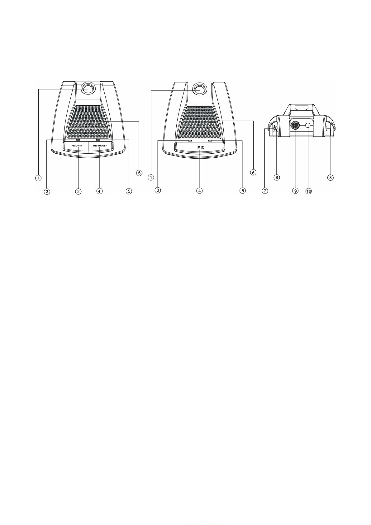
CR-M 102/ B
Features
CR-M41 2B Front View CR-M41 4B Front View Rear View
① MIC jack
② PRIOVITYKey
③ POWER
④ MIC ON/OFF
⑤ MIC indicator light
⑥ Build-in loudspeaker
⑦ Volume adjustment
⑧ Earphone jack
⑨ Link jack
⑩ Cable
Features
1, voting function integrated.
2, 8-pin aviation connector
3. Pluggable unidirectional microphone with red ring indicator.
4, 2M cable for each unit
5, Knob pin MIC pole
6, Build-in flat panel loudspeaker and earphone jack with excellent audio quality and adjustable
volume control.
7, Chairman Unit has the function to approve or deny the talking request from delegate units.
8, Chairman Unit is not limited by the active microphone limitation.
9, Chairman Unit can cut the microphone of delegate units at any time to manage and control the
whole conference conveniently
1 , There is no limitation for the chairman unit. It can be located anywhere in the daisy chain. Power
supplied by the central control unit with 24V safety current.
12
Diagram
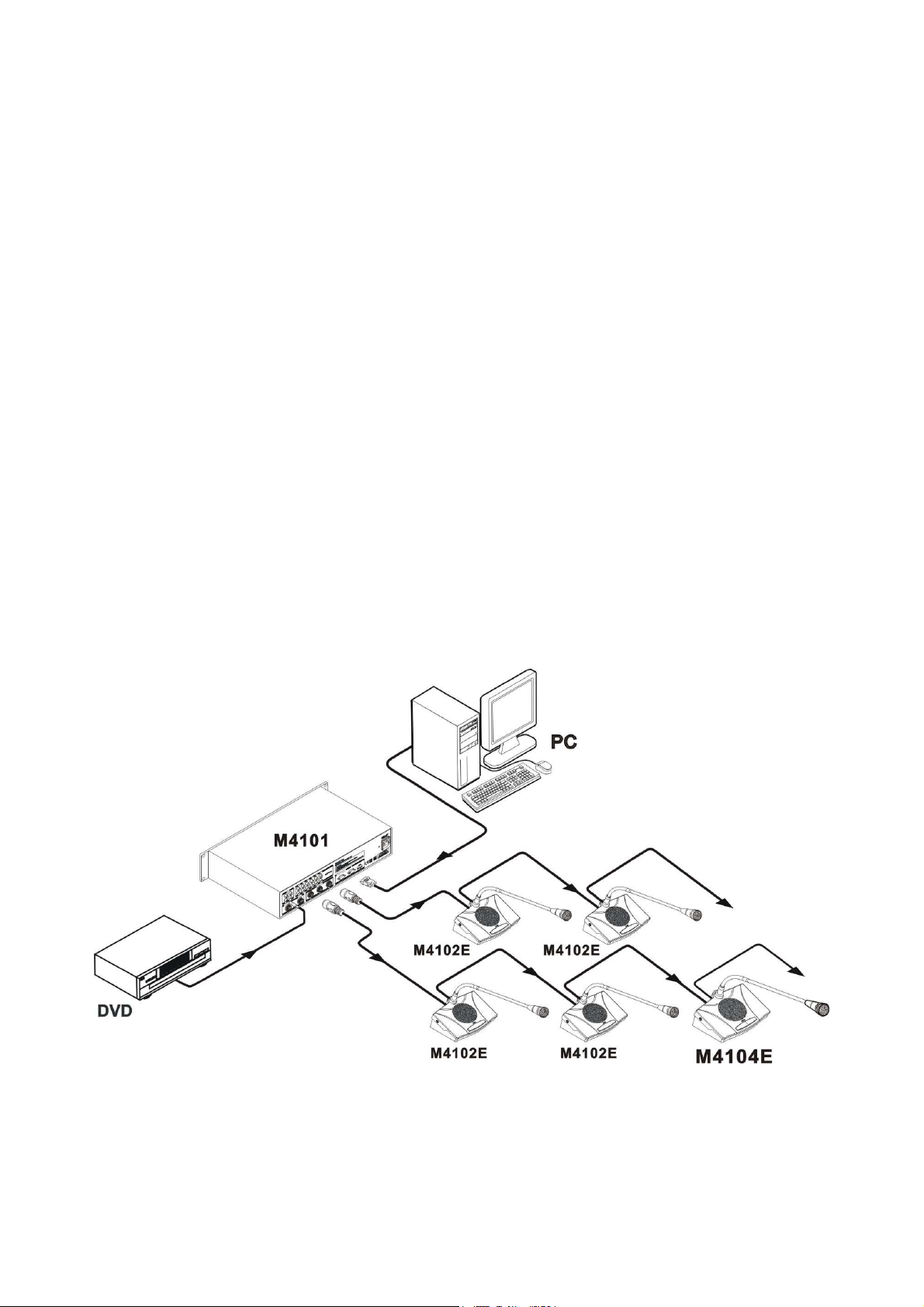
CR-M 102/ E
Features
Side View Front View Side View
MI
C
P
H
O
NE
O
N/
O
F
F
D IG ITA L C O N F E R E N CE S Y S TE M
D IG ITA L C O N F E R E N CE S Y S TE MD IG ITA L C O N F E R E N CE S Y S TE M
D IG ITA L C O N F E R E N CE S Y S TE M
1
2
3
1
6
4
5
78
Rear View
① Earphone jack
② MIC jack
③ Build-in loudspeaker
④ MIC indicator light
⑤ MIC on/off
13
⑥ Volume adjustment
⑦ Cable
⑧ Link connector
Features
1, voting function integrated.
2, 8-pin aviation connector
3. Pluggable unidirectional microphone with red ring indicator.
4, 2M cable for each unit
5, Knob pin MIC pole
6, Build-in flat panel loudspeaker and earphone jack with excellent audio quality and adjustable
volume control.
7, Chairman Unit has the function to approve or deny the talking request from delegate units.
8, Chairman Unit is not limited by the active microphone limitation.
9, Chairman Unit can cut the microphone of delegate units at any time to manage and control the
whole conference conveniently
1 , There is no limitation for the chairman unit. It can be located anywhere in the daisy chain. Power
supplied by the central control unit with 24V safety current.
11, the flat panel loudspeaker will automatically mute to avoid howling when the microphone turns
on.
Diagram
14
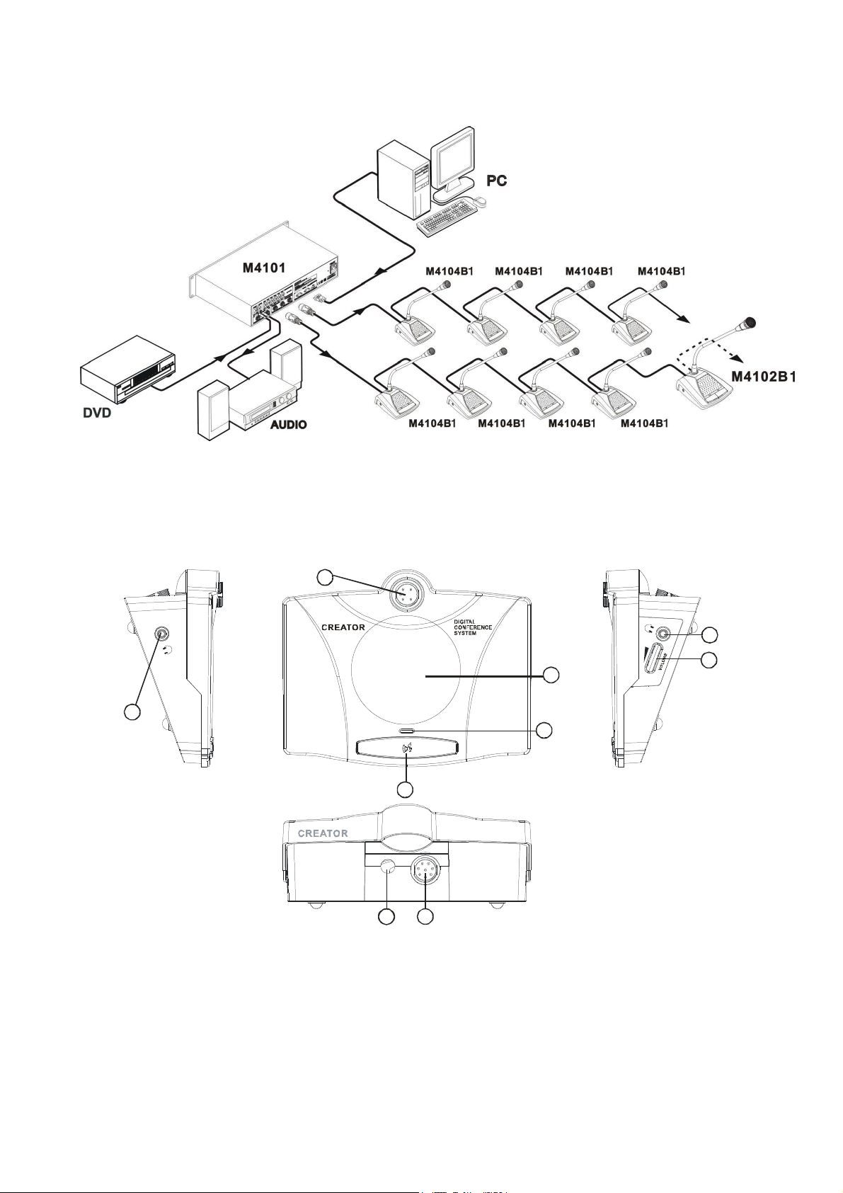
Embedded Unit
Features
CR-M41 2C1Front View CR-M41 4C1Front View
12 3
MIC /BREAK
C REATOR
4 0. 00 m m
MIC
CREATOR
12 3
40 m m
1 29 mm 1 2 9 mm
CR-M41 2C4Front View CR-M41 4C4Front View
CREATOR
4
CREATOR
129mm 12 9 mm
4
0
m
m
4
0
m
m
4
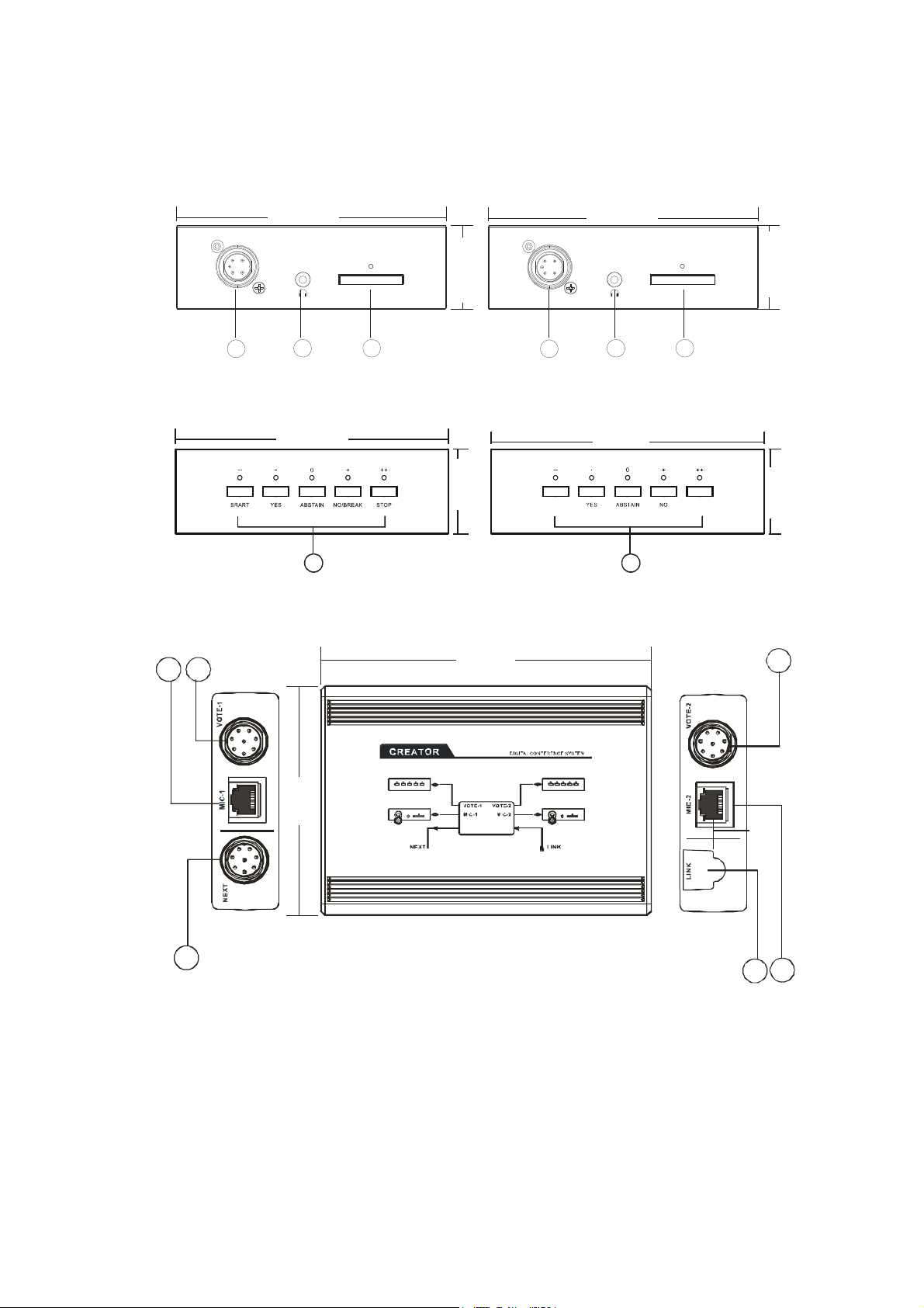
CR-MC4 32B/CR-MC4 34B
6
121. mm
24 .5 m m
86. mm
57
78
8
① MIC jack
② Earphone jack
③ MIC——ON/OFF,long press for 3 seconds of Chairmane unit can stop active delegate unit.
④ Multi voting buttons
“1,2,3,4,5”
——For/against: buttons 2/3/4 stand for For/Abstain/Against, respectively.
——Multiple election: buttons 1/2/3/4/5 can stand for different candidates, respectively.
——Evaluation Poll: buttons 1/2/3/4/5 stand for 5 level /-/ /+/++, from low to high.
This manual suits for next models
24
Table of contents
Other Creator Electronics Conference System manuals


Popular Conference System manuals by other brands

Crestron
Crestron UC-BX31-T-INDIA quick start guide

MantaroBot
MantaroBot TableTop TeleMe quick start guide

BMW Motorrad
BMW Motorrad Communication system operating instructions

Polycom
Polycom SoundStructure C16 Hardware installation guide

PictureTel
PictureTel Venue-2000 Administrator's guide

LAIA
LAIA CUTE 4K user manual


