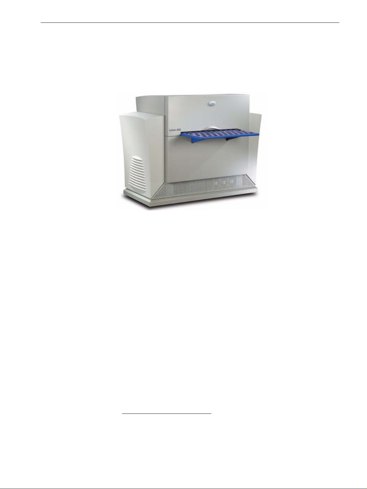
Creo Lotem 400 Series Operating instructions

www.creo.com
Site Preparation Guide
English
Lotem 400 /
Lotem 400 Quantum
Family
707-00144D-EN

Copyright
Copyright © 2006 Creo Inc. All rights reserved. The Creo wordmark, Creo logo, and the names of the Creo
products and services referred to in this document are trademarks of Creo Inc.
Adobe, Acrobat, Adobe Illustrator, Distiller, Photoshop, PostScript, and PageMaker are trademarks of Adobe
Systems Incorporated.
Apple, iMac, Power Macintosh, Mac OS, AppleShare, AppleTalk, TrueType, ImageWriter, and LaserWriter are
registered trademarks of Apple Computer, Inc. Macintosh is a trademark of Apple Computer, Inc., registered in
the U.S.A. and other countries.
PANTONE, Hexachrome, PANTONE Hexachrome, and PANTONE MATCHING SYSTEM are the property of
Pantone, Inc.
PEARL, PEARLsetter, PEARLhdp, PEARLdry, and PEARLgold are registered trademarks of Presstek, Inc.
XEROX® is a trademark of XEROX CORPORATION.
Other brand or product names are the trademarks or registered trademarks of their respective owners.
No copying, distribution, publication, modification, or incorporation of this document, in whole or part, is
permitted without the express written permission of Creo Inc. In the event of any permitted copying, distri-
bution, publication, modification, or incorporation of this document, no changes in or deletion of author
attribution, trademark legend, or copyright notice shall be made. No part of this document may be
reproduced, stored in a retrieval system, published, used for commercial exploitation, or transmitted, in any
form by any means, electronic, mechanical, photocopying, recording, or otherwise, without the express written
permission of Creo Inc. This document is distributed in Adobe Systems Incorporated's PDF (Portable
Document Format). You may reproduce the document from the PDF file for internal use. Copies produced
from the PDF file must be reproduced in whole.
Creo Inc.
3700 Gilmore Way
Burnaby, B.C., Canada
V5G 4M1
Tel: +1.604.451.2700
Fax:+1.604.437.9891
http://www.creo.com
Internal 707-00144D-EN
Revised January 2006

Lotem 400 / Lotem 400 Quantum Family Site Preparation Guide 1
Introduction.................................................................................................................................................... 1
Tools Needed.................................................................................................................................................. 2
Antivirus Software .......................................................................................................................................... 2
Equipment Overview 3
Options .......................................................................................................................................................... 4
Size and Weight ............................................................................................................................................. 4
Cables, Connectors, and Receptacles .............................................................................................................. 5
Site Requirements 7
Footprint and Working Area ........................................................................................................................... 7
Debris Removal Cabinet.................................................................................................................................. 8
Environmental Conditions............................................................................................................................... 9
Floors ............................................................................................................................................................. 9
Electrical ....................................................................................................................................................... 10
Power Quality ........................................................................................................................................ 10
Heat Output .......................................................................................................................................... 11
Power Line Voltage/Frequency ............................................................................................................... 11
Power Line Disturbances ........................................................................................................................ 11
Grounding ............................................................................................................................................. 11
Air Supply..................................................................................................................................................... 13
Air Supply Qualification Procedure ......................................................................................................... 14
Cleanliness............................................................................................................................................. 14
Static Electricity...................................................................................................................................... 14
Humidity................................................................................................................................................ 15
UV Light ................................................................................................................................................ 15
Air Conditioning .................................................................................................................................... 15
Ventilation.................................................................................................................................................... 15
Telephone Link ............................................................................................................................................. 17
Network ....................................................................................................................................................... 17
Media and Processor(s) ................................................................................................................................. 17
Plates............................................................................................................................................................ 17
Plate Registration.......................................................................................................................................... 18
Shipment and Delivery 19
Customer Responsibilities ............................................................................................................................. 19
Forklift ................................................................................................................................................... 19
Doors and Hallways ............................................................................................................................... 19
Shipping Crates ............................................................................................................................................ 20
Contents

2 Lotem 400 / Lotem 400 Quantum Family Site Preparation Guide

Lotem 400 / Lotem 400 Quantum
Family Site Preparation Guide
Introduction
Please take a few moments to read through this document. It provides guidelines
for preparing your site for the Lotem 400 / Lotem 400 Quantum platesettter
installation.
Your Creo service engineer will help you to ensure that your site meets all the
requirements. Proper preparation will help to prevent unnecessary problems and
delays when installing the device.
The following topics are discussed:
•Device configuration
•Floor space requirements
•Device dimensions
•Weight requirements
•Electrical requirements
•Debris removal system requirements
•Environmental conditions
•Ventilation requirements
•Network/modem requirements
•Processor specifications
With your Creo service engineer, complete the Site Inspection Checklist in
Appendix B.

2 Lotem 400 / Lotem 400 Quantum Family Site Preparation Guide
Tools Needed
•Air Supply Gauge (92-0373A)—to check the pressure and flow of the site’s
compressed air supply. See Air Supply Qualification Procedure on page 14.
•Floor Level Gauge ( 92-0373A)—to check the pressure and flow of the sites’
compressed air supply. See Air Supply Qualification Procedure on page 14.
•Tape measure—15 m (50 ft.)
Antivirus Software
Note: Creo supports and recommends that the customer purchase a copy of the latest
version of Symantec Antivirus Corporate Edition software. They should install it on each of
their Creo CTP Systems. Creo does not sell Symantec Antivirus software, nor do we install
or directly support it. We recommend that the customer purchase the software from a
retail vendor convenient to them. We will supply installation instructions to customers
who have signed and returned the Antivirus Waiver to Creo. To find a copy of the
Antivirus Waiver, the customer should log onto eCentral and select Self Support >
Product Documentation and type word Antivirus in the search criteria.
See the Installing Norton Antivirus document on eCentral for installation details.
Equipment Overview 3
Equipment Overview
The device consists of the following standard components:
•Platesetter
•Universal debris removal system1
1.The debris removal system consists of a vacuum pump and filtration system for
removing debris from exposed media. See the UDRC Site Preparation and
Requirements document ( 725-00089A).
4 Lotem 400 / Lotem 400 Quantum Family Site Preparation Guide
Options
The Lotem 400 Family includes:
•Lotem 400 platesetter
•Lotem 400 platesetter with (multi-cassette unit) MCU
•Lotem 400 platesetter with processless plates (chemistry free)
•Lotem 400 Xpose platesetter
The Lotem 400 Quantum Family includes:
•Lotem 400 Quantum platesetter
•Lotem 400 Quantum platesetter with MCU
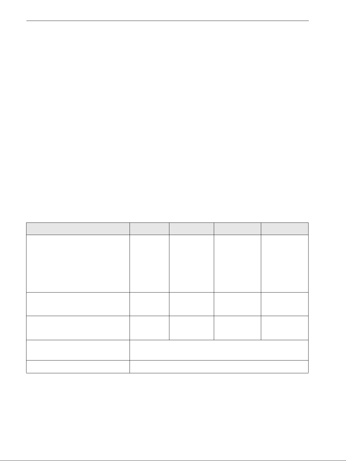
Size and Weight
Table 1 shows the maximum dimensions and weight of the Lotem 400 / Lotem 400
Quantum Family output devices and their components. The measurements are
taken facing the Lotem 400 / Lotem 400 Quantum Family output devices, with the
panels installed.
For measurements of the crates as shipped, see Table 6 on page 20.
Table 1: Size and weight of Lotem 400 / Lotem 400 Quantum Family platesetter and devices
Device Width Length Height Weight
Lotem 400
Lotem 400 Quantum platesetter
1750 mm
(69 in.)
1450 mm
(57 in.)
[includes
508 mm
(20 in.)
loading tray]
1350 mm
(53.15 in.)
750 kg
(1650 lb.)
MCU for Lotem 400 1220 mm
(48 in.)
1600 mm
(63 in.)
1350 mm
(53.15 in.)
650 kg
(1430 lb.)
Loading tray 450 mm
(17.72 in.)
Debris removal cabinet See the UDRC Site Preparation and Requirements document
(725-00089A).
Workstation Varies with configuration

Equipment Overview 5
Cables, Connectors, and Receptacles
Tables 2–4 list the supplied and required cables and connectors for the output
devices. Table 5 on page 6 lists the power/air connections.
Table 2: Cables and Interconnects—North America
Table 3: Cables and Interconnects—Europe, Australia and S.E. Asia
Note: Creo does not supply the connectors.
Cables Supplied by Creo Supplied by customera
a. The tolerances for input voltages are +6%, –10%. The specification for the frequency is 50/60Hz ±1.5%.
Branch circuits should have time delay type circuit breakers to avoid nuisance tripping caused by inrush
currents. For details, see Electrical on page 10.
Output device main power Yes
Workstation power Yes
Debris removal cabinet
power
See the UDRC Site Preparation and Requirements document
(725-00089A).
Telephone line Modem and serial cable.
Modem power supply can be
plugged into UPS.
Dedicated telephone line and
RJ-11 cable to plug into modem
(must be long enough to reach
workstation)
Cables Supplied by Creo Supplied by customera
a. The tolerances for input voltages are +6%, –10%. The specification for the frequency is 50/60Hz ±1.5%.
Branch circuits should have time delay type circuit breakers to avoid nuisance tripping caused by inrush
currents. For details, see Electrical on page 10.
Output device main power IEC320, type C20 appliance inlet Dedicated 16A, 200–240 V branch
circuit with IEC 309 16 A
receptacle
Workstation power IEC320, type C14 inlet IEC320, type C13 connector with
8Acord
Dedicated 8 A, 200–240 V branch
circuit
Debris removal cabinet
power
See the UDRC Site Preparation and Requirements document
(725-00089A).
Telephone line Serial cable for modem Modem, dedicated telephone line,
and telephone cable long enough
to reach workstation. Also
requires separate AC power
source (UPS provided only with
IEC type 320 outlet receptacles).

6 Lotem 400 / Lotem 400 Quantum Family Site Preparation Guide
Table 4: Cables and interconnects—Japan
Table 5: Air and network connections
Cables Supplied by Creo Supplied by customera
Output device main power
(attached to either the Single
Cassette Unit or Multiple
Cassette Unit)
IEC320, type C20 appliance inlet
2.5 m (8.2 ft.) power cord with
IEC320 type C19 connector at
equipment end and L6-20P
connector at other end
L6-20R receptacle
Dedicated 20 A, 200 V branch
circuit with L6-20R receptacle
Workstation power 2.5 m (8.2 ft.) power cable with
5-15P connector
5-15R receptacle and dedicated
100V, 15A branch circuit
Debris removal cabinet
power
See the UDRC Site Preparation and Requirements document
(725-00089A).
Telephone line Serial cable for modem. Modem, dedicated telephone line,
and telephone cable long enough
to reach workstation. Also
requires separate AC power
source (UPS provided only with
5-15R receptacles).
a. The tolerances for input voltages are +6%, –10%. The specification for the frequency is 50/60Hz ±1.5%.
Branch circuits should have time delay type circuit breakers to avoid nuisance tripping caused by inrush
currents. For details, see Electrical on page 10.
Other connections Supplied by Creo Supplied by customera
a. For the location of the air supply, see Footprint and Working Area on page 7. For further details, see Air
Supply on page 13 and Network on page 17.
Network connection
(for connecting to the
workflow)
Ethernet:
100 Base-T (RJ-45)
Network connection and cable
long enough to reach workstation.
FDDI: Duplex SC
Shop air supply (dedicated
branch recommended—see
Air Supply on page 13)
0.5 in. national pipe thread (NPT)
female fitting on the device
A flexible air line, 0.75 in. ID
min., with 0.5 in. NPT fitting at
the end for connecting to the
Lotem 400 / Lotem 400 Quantum
Family.
The air line must be capable of
delivering 20 SCFM @ 90 psi.
Keep the air line as short as
possible and free from
restrictions. If the air line is longer
than 6.1 m (20 ft.), use a larger ID
airline.

Site Requirements 7
Site Requirements
Footprint and Working Area
Ask your service representative to see TechPlanet for the recommended work area
and dimensions for your specific Lotem 400 / Lotem 400 Quantum configuration.
Allow a recommended minimum 1200 mm (47.24 in.) at the front of device, and
1000 mm (39.37 in.) at the sides of device for operator access:
Figure 1: Footprint of Lotem 400/Lotem 400 Quantum with slider kit

8 Lotem 400 / Lotem 400 Quantum Family Site Preparation Guide
Figure 2: Footprint of Lotem 400/Lotem 400 Quantum platesetter
Provide an area close to the device for storing media (for immediate use), disks,
paperwork, and so on.
Debris Removal Cabinet
Certain printing media (plates or film) may release airborne emissions during the
imaging process. Creo output devices are supplied with—or may be able to be
upgraded to—a debris removal system containing a collection nozzle located on
the head and a filtration unit, such as the Universal Debris Removal Cabinet
(UDRC).
The debris removal system is designed to extract and filter the airborne emissions,
thus contributing to a healthier working environment, consistent image quality,
and general reliability and cleanliness of the imaging device. Some types of media
typically release both particulate and gaseous emissions. Other types of media,
under certain imaging conditions, may release largely particulate emissions.
The UDRC configuration may include various filter options tailored to suit specific
qualified media types. The configuration for a particular customer site is typically
specified in a Creo proposal, sales agreement, order form, product specification, or
equivalent document.
The cabinet must be located within the cable and hose limitations.
For more information on the debris removal cabinet, please see the UDRC Site
Preparation and Requirements document (725-00089A).
WARNING: Emissions, either particulate or gaseous, that are not properly filtered can
endanger your health. For a list of airborne emissions that pertain to the media you are
using, see the media MSDS or contact the media manufacturer or distributor directly.
WARNING: Filtration of airborne emissions is not 100% efficient and must be
complemented by adequate outdoor air room ventilation. Failure to ensure adequate
ventilation may result in exposure to airborne emissions in excess of applicable regulatory
limits and in possible discomfort, illness, injury, and/or disability.

Site Requirements 9
Environmental Conditions
Install the device in a clean prepress area wherever possible. It is not advisable to
install the device in a pressroom environment.
The operating environment for the Lotem 400 / Lotem 400 Quantum Family
devices must be:
Te m p e r a t u r e 2 0 o—30oC (68o–86oF)
Humidity 55%—±5% RH, non-condensing
For the UDRC operating environment, please see the UDRC Site Preparation and
Requirements document (725-00089A).
Floors
The floor must be level and not subject to high levels of vibration. If the customer
site is close to heavy car or rail traffic routes, or is near an industrial site, the device
may be exposed to high levels of vibration through the floor.
Note: Some media types may restrict the operating environment of the Lotem 400 /
Lotem 400 Quantum Family devices. Consult the media manufacturer for their
recommended temperature and humidity ranges for plate operation and storage.
10 Lotem 400 / Lotem 400 Quantum Family Site Preparation Guide
Electrical
The dedicated branch circuit for the following components must be supplied from
the same AC supply panel to ensure that both branch circuits are at the same
ground potential:
•Output device main power
•Wor ks tation ma in p ower
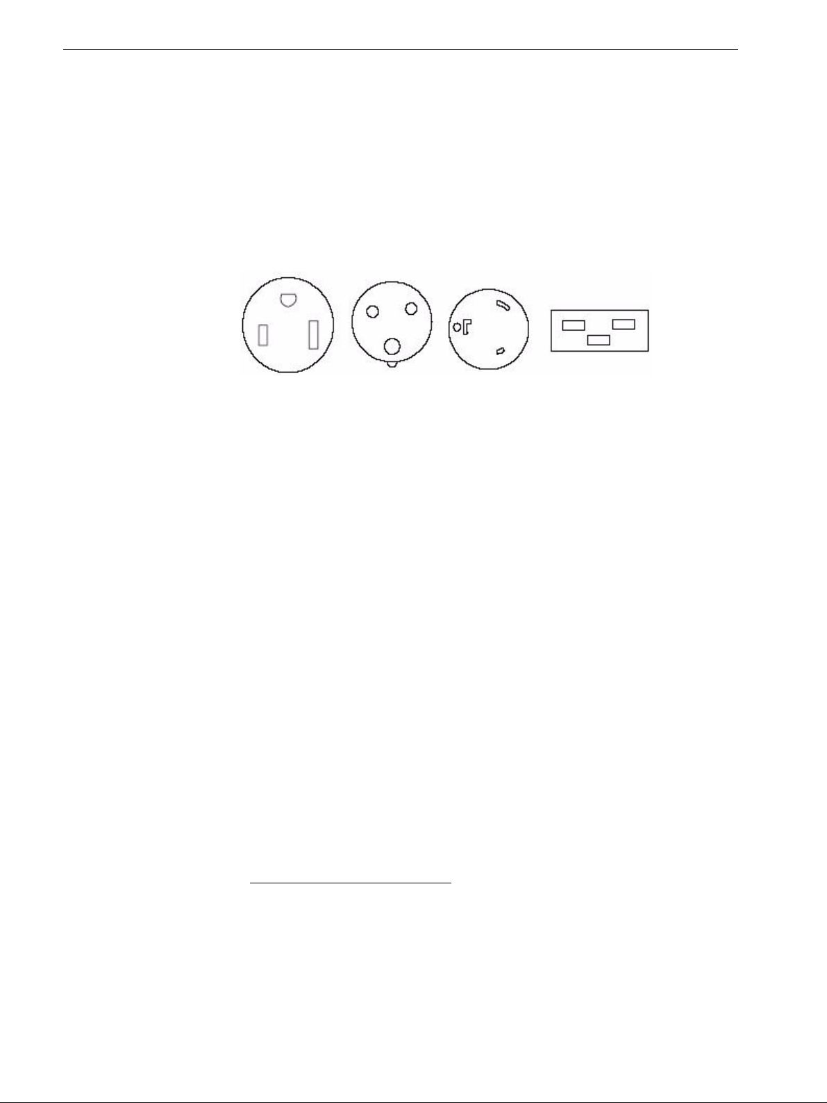
Figure 3 shows the configuration of the receptacles used by the output devices and
peripheral equipment.
Figure 3: Receptacles used on output devices
Power Quality
Before installing the device, a power monitor should be placed at the site to
measure power quality for one week1. If the power quality at the customer site is
outside Creo specifications (+6%/–10%), the customer should purchase a line
conditioner, 3000 VA, for the Lotem 400 / Lotem 400 Quantum Family circuit
from a local supplier.
If there are concerns about power quality (blackouts or brownouts) at the
customer site, an online uninterruptible power supply (UPS) device can be ordered
directly from a local supplier. A UPS is designed to allow the correct and complete
shutdown of the device, as opposed to a line conditioner that is designed to allow
the device to function for extended periods of time where the power conditions
may be outside of the Lotem 400 / Lotem 400 Quantum specifications.
UPS specifications are available from the supplier.
Special Precautions
The plug(s) on the power cord(s) of the workstation are intended for each separate
device. Therefore, the branch circuit receptacle(s) must be installed near the
workstation and be easily accessible.
5-15R IEC320IEC309 L6-20R
1. Creo America has a contract with Re Monitoring Services in Manchester, NH to
provide power and environmental site surveys for the NAFTA region. The monitoring
service includes voltage, current, temperature, humidity, dust and air pressure. Rx
Monitoring Services will provide the equipment to be installed at the customer site for
a maximum of 10 days. They will then monitor it and send a report via e-mail. Outside
North America, contact your local product support specialist.

Site Requirements 11
Heat Output
The nominal heat output of the output device itself is 22,250-26,250 BTU/hr.
For heat output of the UDRC, please see the UDRC Site Preparation and
Requirements document (725-00089A).
Power Line Voltage/Frequency
Line voltage at the customer site must remain within +6%/–10% of the
Lotem 400 / Lotem 400 Quantum Family output devices rated voltage of 200 V–
240 V for
110 V countries, or between 180V and 254 V for 220 V countries.
The frequency is 50/60 Hz ±1.5%.
The electrician at the customer site should install the correct outlet to provide
power to the device. The device must be powered from a different line than the
workstation. Tolerances for the specified input voltages require balanced power
inputs (L1–G=L2–G, or L1G=L1–N).
Power connectors must be of the locking type in North America and Industrial
type B in Europe, due to the high leakage current of the equipment. Frequency is
50/60Hz ±1.5%. See “Erratic performance of platesetter - Uninterupptable power
supply (UPS)/power conditioner requirement” document on eCentral.
Power Line Disturbances
The reliable operation of computer systems depends on the availability of relatively
noise-free AC power. Lightning, line faults, or power switching commonly found
in machinery, office equipment, and factory environments, can generate line
transients that far exceed the peak value of the applied voltage. If not attenuated,
these microsecond pulses can disrupt system operation. The power line to the
machine should be run away from electrically noisy power cables. If power line
disturbances are affecting the operation of the machine, the use of a power
stabilizer is highly recommended.
Dips in power should not exceed 30% of nominal voltage, having maximal
duration of 10 ms. Fast transient disturbances on the power line should not exceed
1.0 kV.
Grounding
At 60 Hz sites, 208 Vac (between 2 phases of 120 Vac each).
At 50 Hz sites, 380 Vac grounds.
Grounding requirements for platesetter – and all equipment communicating with
it – should be observed to ensure trouble-free operation.

12 Lotem 400 / Lotem 400 Quantum Family Site Preparation Guide
Grounding requires the following:
•Grounding wires that are insulated and at least equal in size to the phase
conductors.
•Ground impedance less than 2 Ohms.
•A single point and dedicated ground.
•Each system load (such as platesetter, host) is fed through an isolated ground
outlet and has a separate ground, as well as neutral and phase line of equal size
wire.
Note: Chained neutrals and grounds are not permitted
Site Requirements 13
Air Supply
The Lotem 400 / Lotem 400 Quantum output device requires a clean, dry, oil-free,
dust-free, and moisture-free air supply at 7 bar (100 psi), of shop air according to the
table that follows:
*SLPM measured at 7 bar, SCFM measured at 100 psi
A standard 1/4’’ BSP port female outlet connector is required. It should be
mounted on the wall up to 5 m from the device.
The air supply should conform to ISO class 4.
•Maximum particle size 15 µ (0.006 in.)
•Concentration of solid contaminants: 8 mg/m3(0.000216 oz./yd.3)
•Maximum pressure dew point 3°C @ 8 bar [37.4°F @120 psi]
•Maximum oil content 5 mg/m3(0.000135 oz./yd.3)
Examples of typical compressed air systems that you may use:
For Lotem 400
For Lotem 400 with MCU
Configuration Average air consumption* Compressor air supply*
Lotem 400 10 SLPM (0.35 SCFM) 70 SLPM (2.47 SCFM)
Lotem 400 with MCU 90 SLPM (3.18 SCFM) 170 SLPM (6.0 SCFM)
Note: Do not add lubricant.
Note: The temperature of the airline going from the drying device to the machine must
be kept above 3° C.
Manufacturer Kaeser Atlas Copco
Compressor type Piston Piston
Compressor Model Premium-Silant 130/10 LFx-1.0-T20
Air receiver (liter) 10 50
Dryer (230 V-AC) TAH-4 FX1
Automatic Water Drainer according to air receiver according to air receiver
Manufacturer Kaeser Atlas Copco
Compressor type Screw Screw
Compressor Model SX-3 GX2-10 (50 Hz)
Air receiver (liter) 250 (or 280) 250
Dryer (230 V-AC) TA-5 FX1
Automatic Water Drainer ECO-21-PLUS WD80

14 Lotem 400 / Lotem 400 Quantum Family Site Preparation Guide
Air Supply Qualification Procedure
This procedure helps determine whether the customer’s air supply is adequate for
satisfactorily running the output device. It requires a measurement tool
(92-0373A) made specifically to test the output device’s air supply.
1. Mount the device to the end of the air hose or pipe that would normally be
connected to the output device. A few extra adapter fittings and a roll of
Teflon® tape have been included for this purpose.
2. Turn on the valve on the tool.
3. Record the results in Table on page 31.
4. Repeat this test two more times during the day at well-spaced intervals to
confirm that the air supply is not being compromised by other machines, and
so on.
The gauge must never fall below 90 psi at any time during the tests. If the air supply
fails to maintain this pressure at a minimum, it is below specifications for the
output device.
Cleanliness
Filters in the air conditioning system should be able to block 60% of all 10 micron
dust particles.
Clean air is vital as an unclean environment can cause hotspots on your plates as
well as machine malfunction.
According to IEC-721-3-3,7
Name: Mechanically active substances
Class: 3S2, 7S1
Severity: Sand 30 mg/m^3
•Dust (suspension) 0.2 mg/m^3
•Dust (sedimentation) 1.5 mg / (m^2 X h)
Static Electricity
•Humidity must be 55% ±5% to reduce the static electricity with the plates. See
Humidity below.
•Use of floor carpeting is not recommended in the Lotem 400 / Lotem 400
Quantum output device area. If carpets are used, only anti-static carpets
should be installed at the site. Carpet thickness should be up to 0.5 inch (12
mm).

Site Requirements 15
Humidity
The output device requires relative humidity of 55% ±5%.
An industrial steam humidifier can be used to meet specified humidity.
UV Light
Some plates, such as Kodak DITP, are sensitive to UV light. When such plates are
used or when the Lotem 400 / Lotem 400 Quantum output device is directly
connected to a plate stacker, you need an appropriate safe light.
Air Conditioning
Sufficient air conditioning should be present to provide heat dissipation for the
output device, plus all additional equipment residing in the system room, and an
additional minimum 25% safety margin. Ensure that the ventilation system can
circulate the entire volume of air in the room 16 times per hour.
The output device requires a constant temperature of 23×C ±2×C
(73.5×F ±3×F).
The calculated air conditioning requirements for the output device (in BTU/hour)
are shown in below table.
Please note the following guidelines:
•The system room should ideally contain both a thermometer and a
hygrometer, permanently mounted in a central location.
•In addition, it is highly recommended that you have a humidity and
temperature recorder.
Ventilation
No filtration can be 100% efficient (for example, carbon monoxide is not captured
by Creo filters). That is why outdoor air ventilation is required with the debris
removal system. Air exhaust vents (where air is drawn out of the room) should be
located as close to the debris removal cabinet and output device as possible.
The Lotem 400 / Lotem 400 Quantum Family output devices require a minimum
of 1.1 m3/min (40 cfm)1outdoor air ventilation. This air ventilation prevents the
accumulation of airborne emissions that may be released when certain media are
imaged.2
Platesetter 12,000-16,000 BTU/hour
Host 2,500 BTU/hour
Debris removal system 4,800 BTU/hour
Other misc. 1,500 BTU/hour
Safety margin (25% of above) 6,250 BTU/hour
Total 27,050-31,050 BTU/hour

16 Lotem 400 / Lotem 400 Quantum Family Site Preparation Guide
Outdoor air ventilation must not be confused with air circulation in the room that
results from temperature control or humidity control. Outdoor air ventilation may
be roughly estimated to be 10% to 30% of the air circulation rate in the room. To
achieve adequate air mixing, Creo recommends at least 3 ACH (air changes per
hour).
These recommendations apply to a single device with no other equipment in the
room. Other imaging equipment, processors, ovens, HVAC systems, and so on,
may contribute additional emissions to the work environment, increasing the
amount of outdoor air ventilation required.
The customer is responsible for assessing the level of airborne emissions in the
room to ensure that, upon installation of the Lotem 400 / Lotem 400 Quantum
Family, the requirements of local, state, provincial, regional, and national
regulations for occupational health and safety are satisfied. In the event of any
uncertainty about the levels of airborne emissions, the customer should arrange for
an indoor air quality assessment to be conducted by a qualified industrial hygienist.
1.This is a default value. Certain media may require higher ventilation; to check the
recommended value for specific media, please seeseesee CTP Media Imaging
Performance Database (available from your Creo representative), where it will be
specified if different from default.
2. Information on the hazardous compounds released by a particular media during
imaging should be available from the media manufacturer’s Material Safety Data
Sheet or equivalent document.
This manual suits for next models
1
Table of contents
Popular Office Equipment manuals by other brands


Vivo
Vivo DESK-V001G instruction manual

Steelcase
Steelcase Elective Elements Powerway SPB89 installation instructions

hushoffice
hushoffice hushwork HUS-BX-009 Maintenance and safety manual

LDI
LDI Safco 5228 Assembly instructions

Framery Q
Framery Q Maggie installation instructions

Steelcase
Steelcase FlipTop Twin Assembly instruction


